

Page 1

WHETSTONE SHARPENER
MODEL NO: CWS250
PART NO: 6500498
OPERATING & MAINTENANCE
INSTRUCTIONS
ORIGINAL INSTRUCTIONS GC05/24-Rev 2
Page 2

INTRODUCTION
Thank you for purchasing this CLARKE Whetstone Sharpener.
Before attempting to use this product, please read this manual thoroughly and
follow the instructions carefully. In doing so you will ensure the safety of yourself
and that of others around you, and you can look forward to your purchase
giving you long and satisfactory service.
SPECIFICATIONS
Feature Value
Product Dimensions (L x W x H) mm 388 x 300 x 409 (excl work support)
Weight 10.35 kg
Grinding Stone Dimensions (D x T) 250 x 50 mm (12 mm bore)
Honing Wheel Dimensions (D x T) 200 x 30 mm (12 mm bore)
Drive spindle speed 30-150 rpm
IP Rating IP20
Rated Voltage / Frequency 230 V / 50 Hz
Input Wattage 60 W
Input Ampere (typical load) 0.55 A
No Load Spindle Speed 30-150 rpm (variable)
Duty Cycle Classification S1
Sound pressure 66.7 dB (A)
Guaranteed sound power level 91.5 dB (A)
Sound Power Measured (Lwa dB) 79.4 dB (A)
Uncertainty factor 3.0 dB
2
Parts & Service: 020 8988 7400 / E-mail: [email protected] or [email protected]
Page 3

GENERAL SAFETY RULES
CAUTION: FAILURE TO FOLLOW THESE PRECAUTIONS COULD RESULT IN
PERSONAL INJURY, AND/OR DAMAGE TO PROPERTY.
WORK ENVIRONMENT
1. Keep the work area clean, tidy and well lit. Cluttered and dark areas invite
accidents
2. DO NOT operate power tools in explosive atmospheres, such as in the
presence of flammable liquids, gases or dust. Power tools create sparks
which may ignite the dust or fumes.
3. Keep children and bystanders away while operating a power tool.
Distractions can cause you to lose control.
PERSONAL SAFETY
1. Stay alert, watch what you are doing and use common sense when
operating a power tool. DO NOT use a power tool while you are tired or
under the influence of drugs, alcohol or medication. A moment of
inattention while operating power tools may result in personal injury.
2. Avoid accidental starting. Ensure the switch is in the off position before
plugging in. Plugging in power tools that have the switch on invites
accidents.
3. DO NOT overreach. Keep proper footing and balance at all times. This
enables better control of the power tool in unexpected situations.
4. Dress properly. DO NOT wear loose clothing or jewellery. Keep your hair,
clothing and gloves away from moving parts. Loose clothes, jewellery or
long hair can be caught in moving parts.
5. Gloves, manufactured to the current UK & European safety standards
should be worn when operating grinding equipment.
6. Eye protection manufactured to the current UK & European safety
standards should be worn when operating grinding equipment. Eye
protectors must provide protection from flying particles from the front and
the side.
GENERAL USE AND CARE OF POWER TOOLS
1. ALWAYS check for any damage or condition that could affect the
sharpener’s operation. Any damaged part should be properly repaired.
2. NEVER use the sharpener if it is defective or operating abnormally.
3
Parts & Service: 020 8988 7400 / E-mail: [email protected] or [email protected]
Page 4

3. NEVER abuse the mains cable. Never yank the cable to disconnect it from
the socket. Keep the cable away from sharp edges/hot surfaces.
4. NEVER carry out any alterations or modifications to this product.
5. NEVER wipe the sharpener clean with solvents. Wipe plastic parts with a
soft cloth, slightly dampened with soapy water.
6. NEVER attempt any repairs yourself. If you have a problem with this product
contact your local CLARKE dealer.
7. DO NOT use the tool for any purpose than that described in this manual.
8. ALWAYS maintain the tool with care. Keep it clean for the best and safest
performance.
9. DO NOT force the power tool. Use the correct power tool for your
application. The correct power tool will do the job better and safer at the
rate which it was designed.
10. DO NOT use the power tool if the switch does not turn it on and off. Any
power tool that cannot be controlled with the switch is dangerous and
must be repaired.
11. Store idle tools out of the reach of children and DO NOT allow persons
unfamiliar with the power tool or these instructions to operate the power
tool. Power tools are dangerous in the hands of untrained users.
12. Maintain power tools. Check for misalignment or binding of moving parts,
breakage of parts and any other condition that may affect the power
tools operation. If damaged, have the power tool repaired before use.
Many accidents are caused by poorly maintained power tools.
13. Use the power tool and accessories in accordance with these instructions
and in the manner intended for the particular type of power tool, taking
into account the working conditions and the work to be performed. Use of
the power tool for operations different from intended could result in a
hazardous situation.
ELECTRICAL SAFETY
1. Power tool plugs must match the outlet. NEVER modify the plug in any way.
DO NOT use adapter plugs with earthed (grounded) power tools. Correct
plugs and matching outlets will reduce the risk of electric shock.
2. DO NOT abuse the cable. Never use it for carrying, pulling or unplugging
the power tool. Keep the cable away from heat, oil, sharp edges or
moving parts. Damaged or entangled cables increase the risk of electric
shock.
3. DO NOT expose power tools to rain or wet conditions. Water entering a
power tool will increase the risk of electric shock. If operating the power
4
Parts & Service: 020 8988 7400 / E-mail: [email protected] or [email protected]
Page 5

tool in a damp location is unavoidable, use a residual current device
(RCD) protected supply.
4. When operating a power tool outdoors, use an extension cable suitable for
outdoor use. Use of a cable suitable for outdoor use reduces the risk of
electric shock.
GRINDING STONE SAFETY
1. Check the speed of the grindstone before fitting. NEVER use a stone with a
rated speed less than the speed of your grinder. See specification on page
16.
2. The outside diameter and thickness of the stone must be within the
capacity rating of the machine.
3. ALWAYS refer to the label for specified usage and observe the safety
information. DO NOT use for purposes other than specified.
4. ALWAYS use the correct stone for it’s intended task. Using an incorrect stone
can cause serious injury.
5. DO NOT use reducing bushes or adapters to adapt large hole abrasive
grindstones. DO NOT force a grindstone onto a machine or alter the size of
the arbor hole.
6. NEVER use a stone that is chipped, cracked or damaged. Fragments from
a broken or damaged grinding stone can cause serious injury. Make sure
that defective stones are destroyed and not used.
7. Inspect the stone before use for chips, cracks or excess wear. If the stone is
dropped, inspect for damage or install a replacement. After fitting, position
yourself away from the plane of the rotating stone and run the machine at
full speed. Damaged stones may break apart during this test.
8. Bonded abrasive products are breakable and must therefore be handled
with care. The use of damaged or improperly mounted or used abrasive
products is dangerous and can cause serious injuries.
9. Allow the grindstone to do the work. Never force the workpiece against
the stone as this could cause kickback and/or shatter the stone causing
serious injury.
10. Abrasive products shall be handled and transported with care. They should
be stored such that they are not subjected to damage and harmful
environmental influences.
11. NEVER grind on the sides of the grinding wheel.
SHARPENER SAFETY WARNINGS
1. NEVER leave the machine unattended when running. Switch off the
machine and unplug it before leaving.
5
Parts & Service: 020 8988 7400 / E-mail: [email protected] or [email protected]
Page 6

2. ALWAYS use the tool rests to steady the workpiece. If the tool attachments
are not used, the torque of the spinning grinding/polishing wheel may pull
the workpiece from your hands.
3. Hold a hand tool or blade being sharpened firmly to prevent loss of control.
4. ALWAYS check for damaged parts. Before further use any part that is
damaged should be carefully checked to determine if it would operate
properly and perform its intended function. Check for misalignment or
binding of moving parts, breakage of parts and any other condition that
may affect the tool's operation. A part that is damaged should be properly
repaired or replaced at an authorised service center. Following this rule will
reduce the risk of electric shock, fire or serious injury.
NOTE: Bench grinders/sharpeners used in industrial environments may
be subject to the requirements of The Provision and Use of Work
Equipment regulations 1992 (particularly regarding the training
requirement of The Abrasive Wheels Regulations 1970), or other
legislation. If in doubt seek advice.
Please keep these instructions in a safe place for future reference.
SAFETY SYMBOLS
The meanings of the markings and symbols on the product are shown below
Read this manual
before use and keep
in a safe place for
future reference
Ear defenders should
be worn when
grinding.
6
Parts & Service: 020 8988 7400 / E-mail: [email protected] or [email protected]
Wear eye protection
when using this
sharpener.
Wear dust mask when
using the sharpener or
honing wheel.
Page 7
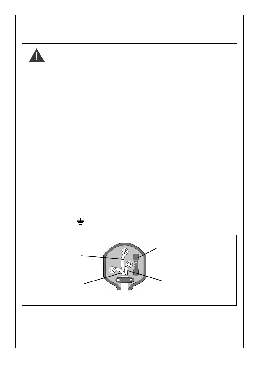
ELECTRICAL CONNECTIONS
Plug must be BS1363/A approved.
Always fit a 13 Amp fuse.
Ensure that the outer sheath of the cable is firmly held by the clamp
Neutral
(Blue)
Live
(Brown)
Earth
(Green and Yellow)
WARNING! READ THESE ELECTRICAL SAFETY INSTRUCTIONS
THOROUGHLY BEFORE CONNECTING THE PRODUCT TO THE
MAINS SUPPLY.
Before switching the product on, make sure that the voltage of your electricity
supply is the same as that indicated on the rating plate. This product is
designed to operate on 230VAC 50Hz. Connecting it to any other power
source may cause damage.
This product may be fitted with a non-rewireable plug. If it is necessary to
change the fuse in the plug, the fuse cover must be refitted. If the fuse cover
becomes lost or damaged, the plug must not be used until a suitable
replacement is obtained.
If the plug has to be changed because it is not suitable for your socket, or due
to damage, it should be cut off and a replacement fitted, following the wiring
instructions shown below. The old plug must be disposed of safely, as insertion
into a mains socket could cause an electrical hazard.
If the colours of the wires in the power cable of this product do not correspond
with the markings on the terminals of your plug, proceed as follows.
•The Blue wire must be connected to the terminal marked N or
coloured Black.
•The Brown wire must be connected to the terminal marked L or
coloured Red.
•The Yellow and Green wire must be connected to the terminal
marked E or or coloured Green.
We strongly recommend that this machine is connected to the mains supply
via a Residual Current Device (RCD). If in any doubt, consult a qualified
electrician. DO NOT attempt any repairs yourself.
Parts & Service: 020 8988 7400 / E-mail: [email protected] or [email protected]
7
Page 8
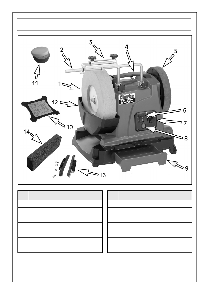
OVERVIEW
No Description No Description
1Grinding wheel 8On/Off Switch Grinding Wheel
2 Tool Support 9 Storage tray
3 Knife Holders/Tool Clamp 10 Angle Guide
4 Carrying handle 11 Tub of Abrasive Paste
5 Honing Wheel 12 Water Trough
6 Forward/Reverse Switch 13 Tank Wiper Brushes
7 Speed control knob 14 Bi-metal Grading Stone
Some items above may be supplied loose in the carton or in the storage tray.
If any are missing or damaged please contact the CLARKE dealer where you
purchased the product.
8
Parts & Service: 020 8988 7400 / E-mail: [email protected] or [email protected]
Page 9
BEFORE USE
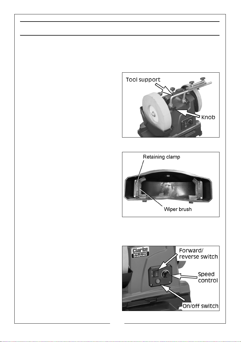
FITTING THE TOOL SUPPORT
The tool support can be used to support grinding jigs/clamps, a trueing or
dressing tool, or as a tool or hand rest when working without jigs.
1. Attach the tool support by
inserting the legs into the two
mounting holes located on the
top of the grinder.
2. Adjust to the desired height,
before tightening the two knobs
to secure it as shown.
• Either front or rear positions can
be used.
FITTING THE TANK WIPER BRUSHES
1. A pair of wiper brushes are
supplied loose for fitting into the
water tank to contain splashes.
Secure them in place by screwing
down the clamps and screws.
2. Fit the water tank in position, lifting
the two small levers to lock it in
place.
PREPARING FOR WORK
Position the machine in good light and on a suitable workbench. It is designed
to be operated from either side, depending upon the grinding or honing task.
1. Plug the machine into the nearest power supply.
2. To start/stop the grinder, press the
ON/OFF switch.
• The grinder can run either
forwards or backwards,
selectable via the 3-position
rocker switch.
3. Press the forward/reverse switch
to the (I) position for rotation anticlockwise when viewed from the
grinding wheel end.
9
Parts & Service: 020 8988 7400 / E-mail: [email protected] or [email protected]
Page 10
4. Press the switch down to (II) for
forward rotation (clockwise when
viewed from the grinding wheel
end).
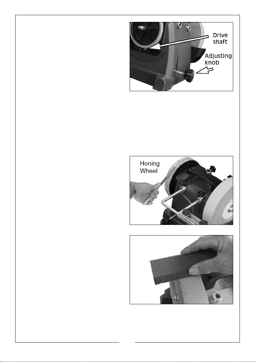
5. If the grinder does not run, turn
the drive adjusting knob until the
drive shaft makes firm contact
with the perimeter of the friction
drive wheel. Do not overtighten.
6. Fill the water trough with clean
water to submerge the bottom of the grinding stone. Let the water soak
into the wheel until there is a continuous puddle on the surface.
• The grinding stone must run in water at all times during operation.
7. During use, re-fill the water trough is when necessary and empty after use
to avoid uneven soaking of the stone
8. Avoid pouring the water residue down a sink as the mass of ground
particles could eventually cause a blockage in household plumbing.
9. When honing, distribute the
abrasive paste (supplied) evenly
onto the honing wheel with a
suitable blade as shown.
This should be sufficient for five to ten
tool honing tasks. This process should
be repeated as required to ensure
the long life of the honing wheel and
achieve a good finish.
DRESSING THE GRINDING STONE
The bi-metal grading stone can be
used to adjust the surface of the
whetstone so as to increase or
decrease its coarseness. When
dressed with the finer side of the
grading stone, the surface is
smoothed over from the original grit
to produce much finer properties.
The rough side of the stone is used to
return the whetstone to its original
coarse, fast cutting state.
10
Parts & Service: 020 8988 7400 / E-mail: [email protected] or [email protected]
Page 11
USING YOUR GRINDER
WARNING: FRAGMENTS FROM A BROKEN/DETACHED GRINDING WHEEL
CAN CAUSE INJURY.
WARNING: ENSURE THAT THE WORKING POSITION ADOPTED DOES NOT
CAUSE OPERATOR FATIGUE WHICH MAY LEAD TO LOSS OF CONTROL OF
THE ITEM BEING GROUND.
WARNING: THE STONE WILL CONTINUE TO ROTATE BRIEFLY AFTER THE
SWITCH HAS BEEN PRESSED.
GETTING STARTED
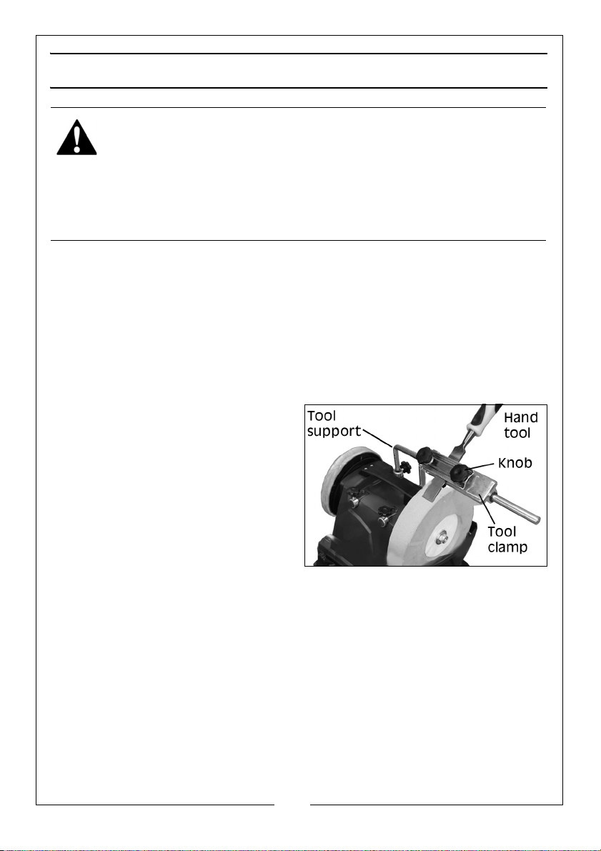
The tool support can be used to support a tool clamp or be used for freehand
grinding of any tools such as axes, pocket knives or woodcarving chisels that
will not fit into any available tool holder.
USING THE TOOL SUPPORT AND CLAMP
The tool clamp is designed for sharpening chisels and plane blades etc. When
using the tool holder proceed as follows.
1. Slide the tool clamp onto the tool
support.
2. Position the clamp directly above
the grinding stone or honing
wheel. Loosen the two knobs on
the tool clamp. Insert the tool
blade (bevelled face
downwards) in the tool clamp,
then firmly tighten the blade in
position as shown.
3. Adjust the tool support so that the tool clamp is a suitable distance from
the grinding stone or honing wheel. Loosen the two knobs on the tool
clamp to adjust the tool blade so that its edge lightly touches the grinding
stone or honing wheel. The correct angle will be determined by using the
Angle Guide as described below.
4. Switch on the grinder and slowly move the tool clamp back and forth
along the tool support to grind the tool blade. If necessary, loosen the
knobs on the tool clamp to re-adjust the blade. After adjustment, check
that the angle is still correct.
11
Parts & Service: 020 8988 7400 / E-mail: [email protected] or [email protected]
Page 12
USING THE ANGLE GUIDE
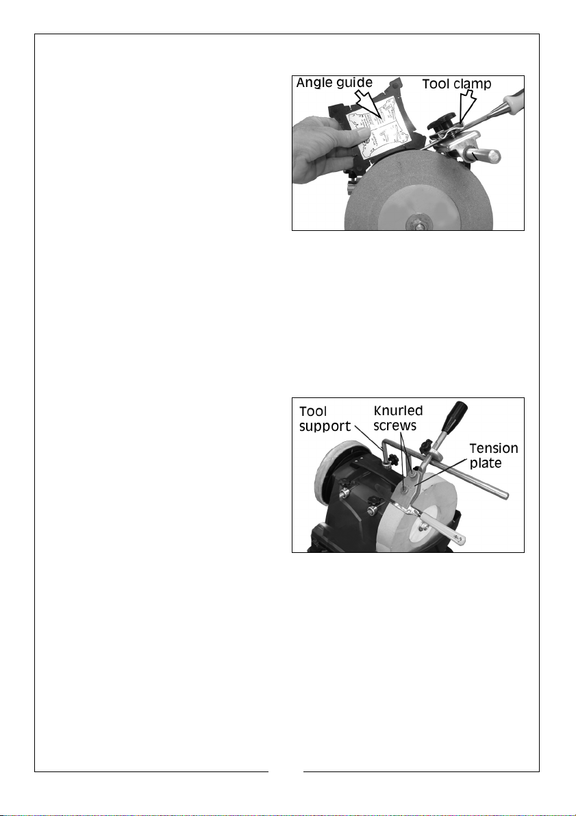
1. The angle guide is used to
determine the cutting edge angle
of a tool. To do so, secure the tool
into the tool clamp, then install
the clamp to the tool support as
shown.
2. With the machine switched off,
hold the angle guide with the
desired angle (as indicated on
the angle guide) at the tool tip.
3. Adjust the height of the tool support so that the front end of the angle
guide, touches the grinding stone. Make sure the angle guide continues to
touch the tool tip.
4. Once the desired angle is achieved, firmly lock the tool support in place
and remove the angle guide.
GRINDING/HONING A KNIFE BLADE
Knives will be sharpened with an equal bevel to each side of the blade as
itemized on the angle guide.
When using knife holders (not
supplied) proceed as follows:
1. Loosen the knurled screw on the
knife holder. Centre the tension
plate along the top edge of the
knife blade then firmly tighten the
knurled screw to set the knife
blade in position.
2. Tighten the knob to secure the
knife blade tightly before starting
work.
3. Set the knife holder on the tool support and adjust the tool support bar
downward so that the knife blade lightly touches the grinding stone or
honing wheel at the correct angle as determined by the angle guide.
4. Turn on the sharpener and grasp the knife holder firmly. Move the knife
holder back and forth along the tool support to grind/hone the knife
blade. Steady your hand against the tool support as you work. The process
will be repeated for the other side after resetting the knife in the holder.
GRINDING TIPS
• After setting the angle, switch on the grinder and start work.
12
Parts & Service: 020 8988 7400 / E-mail: [email protected] or [email protected]
Page 13

• Press the tool blade evenly onto the stone and move the tool
sideways across the stone. Make sure that at least half the width of
the tool cutting edge comes into contact with the sharpening stone
at any time to avoid damage to the stone.
• Allow the stone to do the work. Do not apply excessive downward
pressure on the tool when grinding.
• Make sure the level of water in the tank is adequate. Never attempt
to dry grind.
HONING TIPS
• Never hone against the direction of the honing wheel, which would
cause the tool to cut into the leather honing wheel surface.
• Although you can work “freehand” for the honing process, you will
achieve more precise results by securing the tool with the tool clamp
or tool holder, and setting the honing angle to the angle used when
grinding the tool.
• Press the tool evenly onto the honing wheel near the cutting edge,
and move the tool sideways across the wheel. Ensure that at least
half the width of the cutting edge comes into contact with the
wheel at any time to avoid damage to the wheel.
• Allow the wheel to do the honing, without applying excessive
downward pressure on the tool.
• Always ensure the honing wheel is kept saturated with machine oil
and abrasive paste for best results.
MAINTENANCE
GENERAL MAINTENANCE
Make sure that all components are tight and secure.
Always have any damaged or worn parts repaired or replaced by qualified
service personnel. DO NOT attempt to repair the grinder unless you are
qualified to do so.
The drive motor and bearings are sealed units and require no regular
maintenance. Should you require assistance, contact your local CLARKE
service agent.
The honing wheel may develop a bump after extensive use where the glued
joint in the leather covering stands proud as the leather becomes
compressed. This can be corrected by sanding away the high spot with an
abrasive (sandpaper) block.
13
Parts & Service: 020 8988 7400 / E-mail: [email protected] or [email protected]
Page 14
The stone will wear down with use and may well go out of true. Use a dressing
wheel or stone grader to correct the trueness and to remove worn, glazed
grains from the stone.
The stone will have a finite life expectancy, dependant upon the nature of the
work being done. Periodically, make a note of the wheel diameter and
replace your 10”(250mm) dia wheel if it reduces to as little as 7”(180mm) in
diameter.
INSTALLING A NEW GRINDING STONE
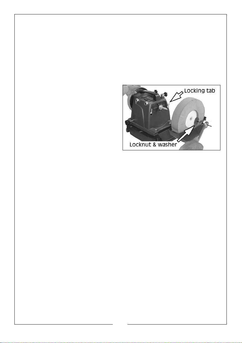
1. Unscrew and remove the locknut
and washer that secures the stone
in place. Grasp the honing wheel
to prevent the drive shaft from
turning while removing the nut.
2. Lift the metal locking tabs holding
the water trough in place and lift
the trough away from the
machine, together with grinding
stone.
• The trough has hooks that fit the slots in the machine body.
3. Discard the old grinding stone and fit the replacement, re-engaging the
water trough with the machine body and locking in place with the metal
tabs.
4. Secure the stone with the locknut and washer. Grasp the honing wheel to
prevent the drive shaft from turning while tightening the nut.
DRESSING A NEW STONE
New grinding stones are frequently not true or in time can become grooved,
glazed (built-up), out of round, or otherwise mis-shapen. To correct these
defects, a grinding stone dresser is available from your CLARKE dealer.
• ET125 Grinding Wheel Dresser - Part No:1700225
• Replacement Dresser Wheel - Part No:1700230
• ET154 ½ Carat Diamond Tip Wheel Dresser - part No:1700329
1. If the grinding stone is new, allow it to spin for a minute with no load. Check
that it is running straight and true. If not, it will require dressing before use.
2. Stand to the side of the stone and hold the dresser handle firmly. Place the
dresser on the tool support so that its wheels can move freely (i.e, the
exposed part of the wheel should be facing up). Run the stone and apply
the dresser to the surface of the stone.
14
Parts & Service: 020 8988 7400 / E-mail: [email protected] or [email protected]
Page 15
INSTALLING A NEW HONING WHEEL
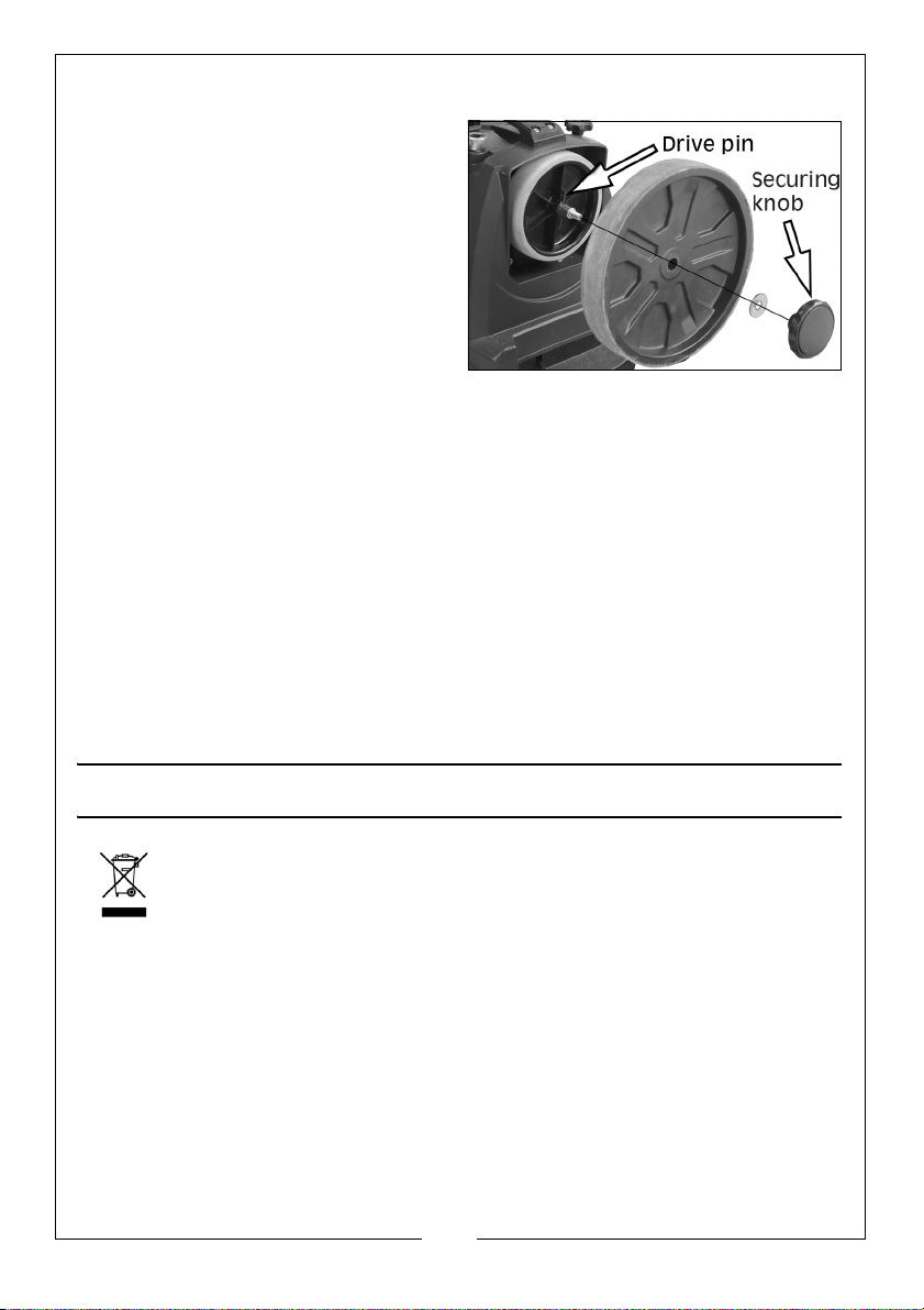
1. Unscrew and remove the securing
knob and washer that secures the
honing wheel in place.
2. Remove the old honing wheel and
fit the replacement, securing it
with the securing knob and
washer. Ensure the drive pin sits in
the groove in the hidden face of
the honing wheel.
CLEANING & STORAGE
Clean the exterior the machine if required using a mild detergent. Never
immerse the machine in water.
To reduce any fire hazard, keep the cooling vents below the grinder free of
debris.
Store the machine in a clean, dry location, out of reach of children.
REPLACEMENT WHEELS
Replacement Grinding and Honing wheels are available from your CLARKE
dealer.
• 250mm dia Grinding Wheel - Part No: 6500556
• 200mm dia Honing Wheel - Part No: 6500557
ENVIRONMENTAL PROTECTION
Do not dispose of this product with general household waste. All tools,
accessories and packaging should be sorted, taken to a recycling
centre and disposed of according to the laws governing Waste
Electrical and Electronic Equipment.
Through the purchase of this product, the customer is taking on the obligation
to deal with the WEEE in accordance with the WEEE regulations in relation to
the treatment, recycling & recovery and environmentally sound disposal of
the WEEE.
In effect, this means that this product must not be disposed of with general
household waste. It must be disposed of according to the laws governing
Waste Electrical and Electronic Equipment (WEEE) at a recognised disposal
facility.
15
Parts & Service: 020 8988 7400 / E-mail: [email protected] or [email protected]
Page 16

TROUBLESHOOTING
PROBLEM CAUSE SOLUTION
Grinder will not
operate.
Motor runs but
wheel not spinning.
Motor gets too hot. Wrong supply voltage. Ensure supply voltage is correct.
Unusual vibration
while working.
No power supply. Check supply & rectify.
ON/OFF switch is faulty. Consult your CLARKE dealer.
Fuse blown. Check & replace if necessary.
Consult your dealer if condition
persists.
Motor faulty. Consult your CLARKE dealer.
Retaining nut not tight. Ensure wheel is correctly
seated. Tighten retaining nut.
See Maintenance on pages14/
15.
Honing wheel not
engaged with drive pin
Drive shaft not pressed
against friction drive
wheel.
Work load too heavy. Reduce pressure applied to
Grindstone mounted
incorrectly/damaged.
Bearings badly worn. Consult your CLARKE dealer.
Loosen wheel & engage wheel
on drive pin. See page 15.
Use the drive adjusting knob to
engage drive mechanism.
workpiece.
Check & rectify. Replace grinding wheel immediately.
GUARANTEE
This product is guaranteed against faulty manufacture for a period of 12
months from the date of purchase. Please keep your receipt which will be
required as proof of purchase.
This guarantee is invalid if the product is found to have been abused or
tampered with in any way, or not used for the purpose for which it was
intended.
Faulty goods should be returned to their place of purchase, no product can
be returned to us without prior permission.
This guarantee does not effect your statutory rights.
16
Parts & Service: 020 8988 7400 / E-mail: [email protected] or [email protected]
Page 17
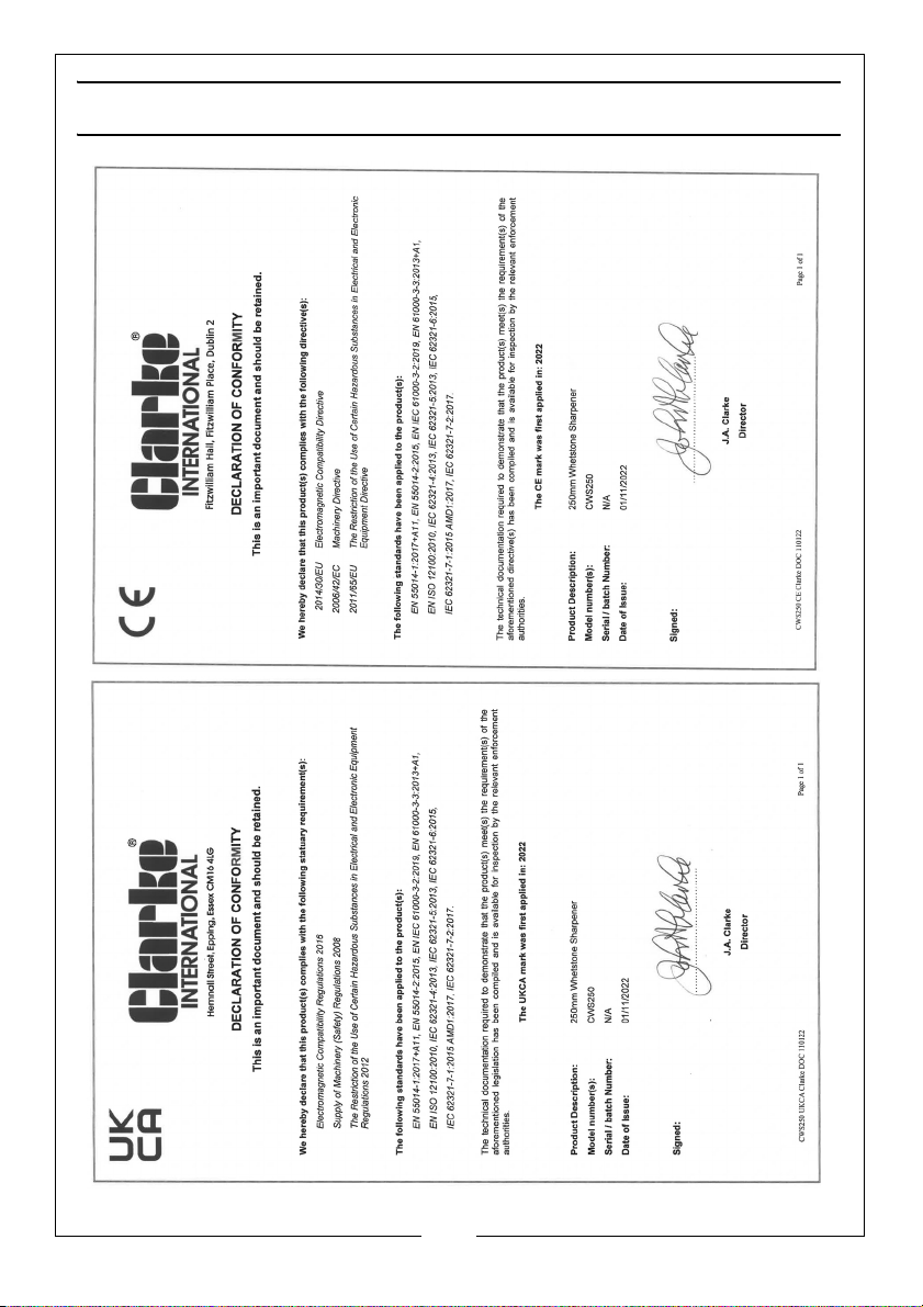
DECLARATIONS OF CONFORMITY
17
Parts & Service: 020 8988 7400 / E-mail: [email protected] or [email protected]
Page 18
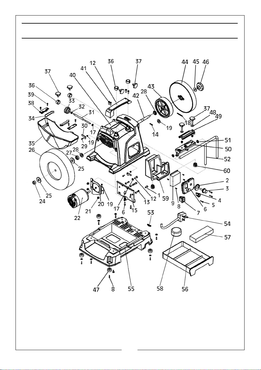
Page 19
COMPONENT PARTS
No Description No Description
1 Bolt 31 Threaded rod
2 Label 32 Nut
Potentiometer 33 Knob for baffle
3
4 On/Off switch 34
5 X-pan headed screw 35 Water tank
6Switchbox cover plate
7 Forward/reverse switch 37 Securing knob
8 X-pan headed screw
9Printed circuit board
10 Switch box
11 Hex socket cap screws 41 X-pan headed screw
12 Handle 42 Main shaft
13 X-pan headed screw 43
14 Pin 44 Leather honing wheel
15 Motor support 45 Big washer
16 X-pan headed screw 46 Securing knob
17 Washer
18 Roll Pin 48 Big washer
19 Washer 49 Tool pressing plate
20 Motor mounting plate 50 Tool bearing plate
21 Locknut
22 Motor 52 Guide Holder
23 n/a 53 Cable clamp
24 Nut 54 Cable & plug
25 Washer 55 Base
26 Grinding wheel 56 Drawer
27 Sleeve 57 Grinding stone
28 Shaft support sleeve 58 Abrasive paste
29 X-pan headed screw 59 Switch box
30 Water tank locking tab 60 Cable gland
Wiper strip
36 Steel sleeve
38 Wiper clamp
39 X-pan headed screw
40 Main housing
Friction Drive wheel
47 Rubber foot
51 Plastic clip
19
Parts & Service: 020 8988 7400 / E-mail: [email protected] or [email protected]
Page 20

 Loading...