

Page 1
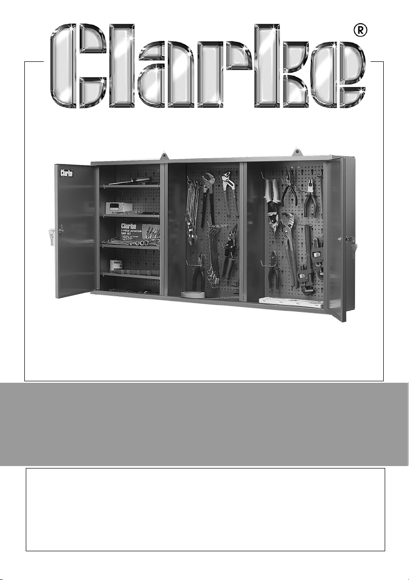
LOCKABLE WALL CABINET
MODEL NO: CWC50
PART NO: 7640020
ASSEMBLY
INSTRUCTIONS
ORIGINAL INSTRUCTIONS GC1118 - Issue 2
Page 2
INTRODUCTION
Thank you for purchasing this CLARKE product.
Before assembling the cabinet be sure to read these instructions thoroughly. In
doing so you will ensure the safety of yourself and that of others around you,
and you can look forward to your purchase giving you long and satisfactory
service.
GUARANTEE
This product is guaranteed against faulty manufacture for a period of 12
months from the date of purchase. Please keep your receipt which will be
required as proof of purchase.
This guarantee is invalid if the product is found to have been abused or
tampered with in any way, or not used for the purpose for which it was
intended.
Faulty goods should be returned to their place of purchase, no product can
be returned to us without prior permission.
This guarantee does not effect your statutory rights.
SPECIFICATION
Model Number CWC50
Weight 17 kg (packed)
Dimensions (L x W x H) 1290 x 203 x 590 mm
2
Parts & Service: 020 8988 7400 / E-mail: [email protected] or [email protected]
Page 3
COMPONENT PARTS
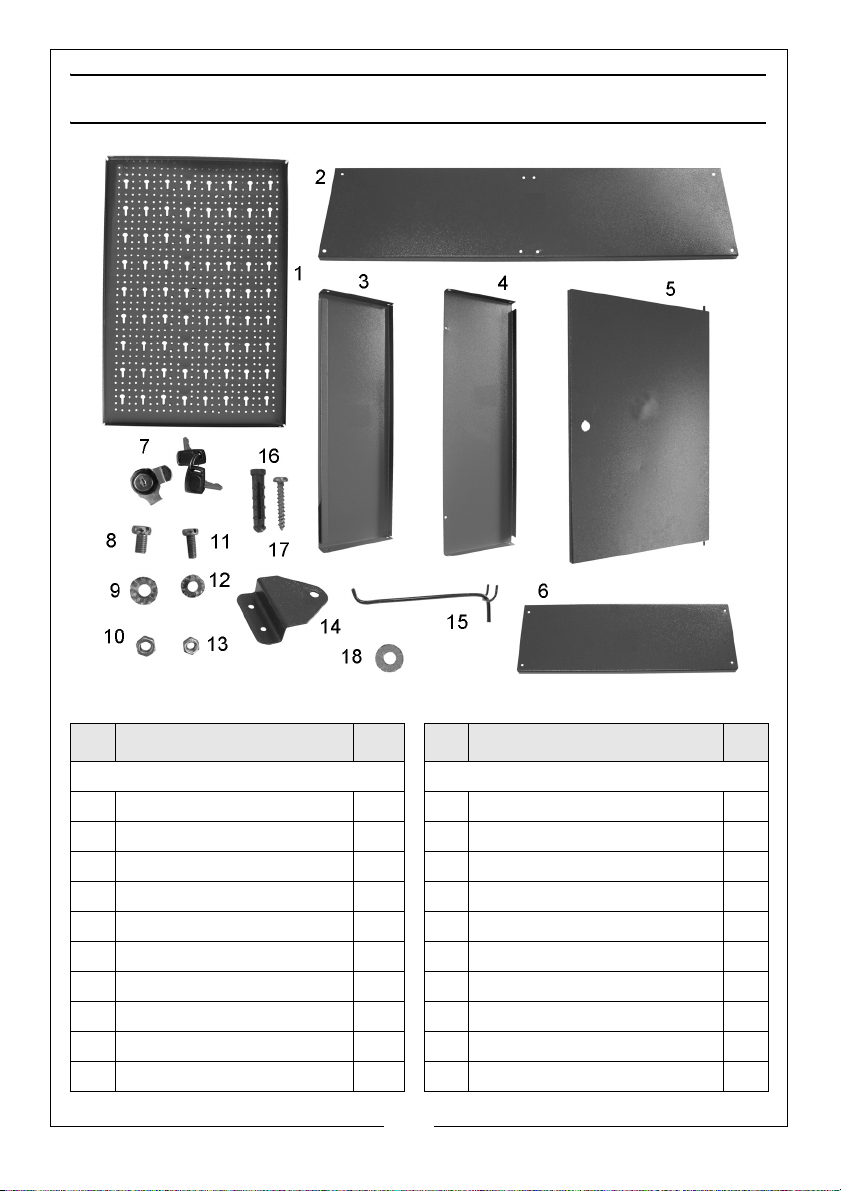
No Description Qty No Description Qty
Large loose items Smaller items in sealed packet
1 Back Panel 3 7 Door Lock set inc key 2
2 Top/Bottom Panel 2 8 Bolt (M5 x 10mm) 20
3 Dividing Panel 2 9 M5 Nut 20
4 End Panel 2 10 Washer 5mm 20
5 Door Panel 2 11 Bolt (M4 x 10mm) 4
6 Shelf Panel 4 12 Nut M4 4
14 Wall Hanging Bracket 2 13 Washer 4
15 Tool Support 10 16 Wall Plug 2
17 Self Tapping Screw 2
18 Flat Washer 3
3
Parts & Service: 020 8988 7400 / E-mail: [email protected] or [email protected]
Page 4
SAFETY PRECAUTIONS
1. Always read the instructions before assembling the unit.
2. Periodically inspect the unit to ensure it is in good condition, replace any
damaged parts.
3. If replacing any parts, only use those supplied by Clarke International,
referring to the parts list on page 3.
Please keep these instructions in a safe place for future reference.
ASSEMBLY
Unpack the parts on to a clean flat area and visually inspect components to
ensure that no damage was suffered in transit, identifying them according to
the parts list and diagram opposite.
Should any damage be apparent, please contact your Clarke dealer.
NOTE: All screw heads should be on the outside of the cabinet. DO NOT
tighten any nuts until the cabinet is fully assembled.
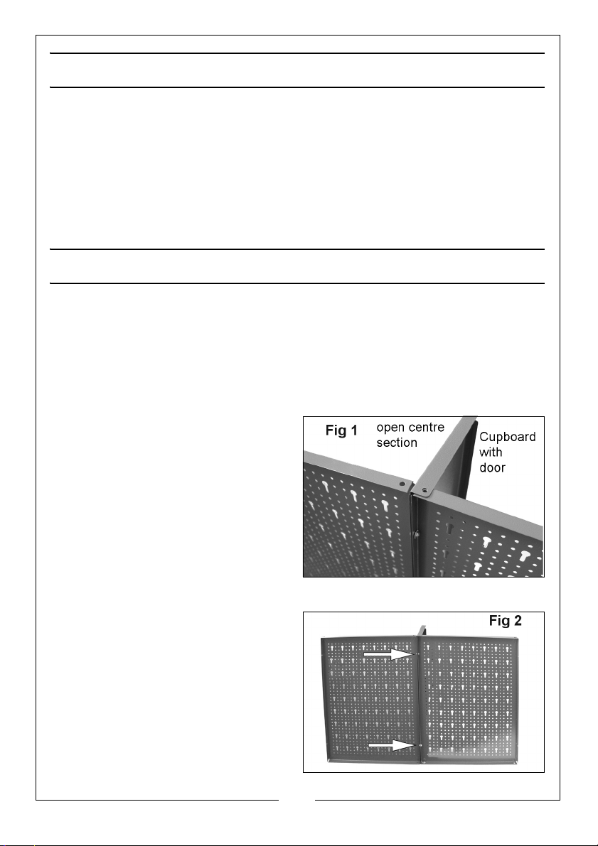
1. Hold the back panels as shown in
Fig 1, with the left/right hand
dividing panels slotted between.
• Ensure that all three back
panels are the same way up
and check the slotted holes are
oriented as shown.
• Ensure that the dividing panels
have their flanges facing each
end of the assembly to create
the closed cupboard sections.
Note that the back panels are of a
folded box section. The folded edges
should be towards the rear of the
cabinet.
2. Line up the holes and insert an M5
bolt at each of the four locations.
Secure with an M5 washer and
nut as shown in Fig 2.
4
Parts & Service: 020 8988 7400 / E-mail: [email protected] or [email protected]
Page 5
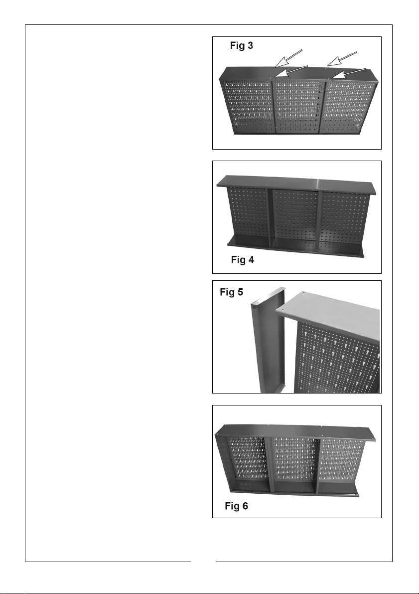
3. Place the top panel in position on
the assembly as shown in Fig 3, so
that the edge with the return fold
lies at the front, and secure loosely
to both the rear and dividing
panels with an M5 bolt, washer
and nut.
4. Lay the assembly down and offer
up the bottom panel (the edge
with the return fold uppermost).
Attach it to the rear and dividing
panels at each intersection as in
Fig 4.
5. Offer up a side panel to one end
as shown in Fig 5. Line up one of
the corner holes and insert an M5
bolt and secure with a washer
and nut.
Repeat at the other three corners.
6. Fit the remaining side panel and
loosely tighten the M5 bolts, 5mm
washers and M5 nuts.
5
Parts & Service: 020 8988 7400 / E-mail: [email protected] or [email protected]
Page 6
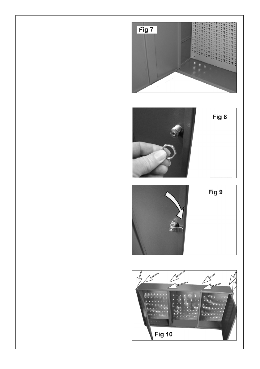
7. Attach the left hand door by
inserting the pivot pins into the
pivot holes in the top and bottom
panels.
• When inserting the door into
the pivot holes you may need
to loosen or temporarily
remove the bolts close to the
pivot points to be able to guide
the door pivots into the holes.
8. Repeat with the other door.
9. Feed the lock barrel through the
door from outside as shown in Fig
8, and secure loosely in place with
the nut.
10. Fit the locking tab to the lock
barrel with the short screw and
washer as shown in Fig 9.
• You can now determine
whether the tab will secure the
door on the up or down stroke.
Locking on the down stroke is
the usual choice. You may
need to re-assemble the lock
and tab to achieve this.
11. With the cabinet lying on a level
surface, wriggle it gently to ensure
that no part is locally stressed,
before progressively tightening all
the nuts
6
Parts & Service: 020 8988 7400 / E-mail: [email protected] or [email protected]
Page 7
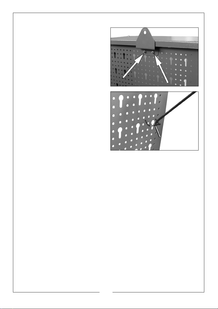
12. Attach the wall hanging brackets
to the back panels as shown in Fig
11, using the M4 bolts, nuts and
washers provided.
• The brackets should not be in
the centre of the back panels
but slightly towards the middle
of the cabinet., nearer the
divisions.
13. The shelves are placed on the
brackets integral to the end/side
panels.
14. Tool supports are suspended from
the back panel and may be
positioned to suit your
requirements as shown in Fig 12, to
suit any collection of tools.
Your wall cabinet is now ready to hang.
Wall plugs and screws are provided for this purpose.
Ensure it is firmly attached to the wall before loading with tools.
SPARE PARTS
Door Lock:- part number DM4802
7
Parts & Service: 020 8988 7400 / E-mail: [email protected] or [email protected]
Page 8
 Loading...