

TOOL STAND
Model No. CUTS1
ASSEMBLY INSTRUCTIONS 0513

Storage
To store the Tool Stand, the legs need to be collapsed, as follows:
Fitrstly remove the Rollers if fitted, and ensure the table extensions are fully IN.
Invert the unit and remove the leg brace by unscrewing the two large knobs,
securing it.
Collapse the legs. Be sure to retain all nuts bolts,knobs and accessories and store
in a safe place.
Specifications
MAXIMUM Load ............................................................................ 125kg
Weight (incl. Accessories) ........................................................... 17.5kg
Overall Dimensions
Min Length ................................................................ 1160mm
Max. Length .............................................................. 1899mm
Width ......................................................................... 608mm
Length (Rollers, centre to centre)
Min ............................................................................. 1058mm
Max. ........................................................................... 1795mm
Height (To surface of Tool Mounting Clamps)
Min. ............................................................................ 614mm
Max. ........................................................................... 760mm
Max Height of Rollers from surface of Tool Clamps .................. 420mm
2

Thank you for purchasing this CLARKE Universal Tool Stand
Although this product is of rugged construction, it should nevertheless be used
with care and consideration, and the precautions closely followed. You can
then look forward to it giving long and reliable service. Immediately on
unpacking the product, please refer to the parts list and satisfy yourself that
all parts are present. Should there be any deficiency, then you should
immediately contact your Clarke dealer, or CLARKE INTERNATIONAL Parts
Department, on 020 8988 7400
Guarantee
This CLARKE product is guaranteed against faulty manufacture for a period of 12
months from the date of purchase. Please keep your receipt which will be required
as proof of purchase.
This guarantee is invalid if the product is found to have been abused in any way,
or not used for the purpose for which it was intended.
Faulty goods should be returned to their place of purchase, no product can be
returned to us without prior permission.
This guarantee in no way affects your statutory rights under common law.
Safety Precautions
• The maximum capacity of this Tool Stand is 125kgs. On no account must this
be exceeded.
• Do not stand on the Cross Members or use as a step ladder, as this could
cause severe damage. Do not stand on top of the Stand.
• Take care when placing a load on to the Tool Stand, It should be placed
gently so that the strain is taken up gradually. Do not drop a load carelessly.
• Always check the Tool Stand for wear, damage or looseness of parts before
use.
• Always ensure you are working on a firm flat surface, and that the Tool Stand
is completely stable.
• DO NOT mount a machine in a manner where work would need to be passed
across the table, as this could cause table instability.
3
Assembly
Remove the components from the packaging and carefully lay them out,
checking to ensure that no damage was suffered during transit.
Should any damage be apparent, please contact your Clarke dealer
immediately.
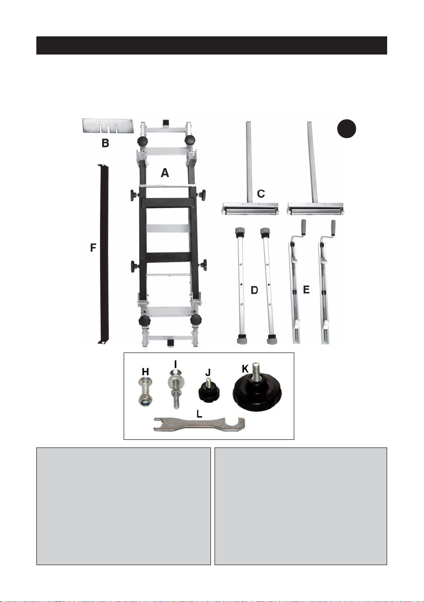
1
A. 1 x Frame c/w Legs
B. 1 x Stop Plate
C. 2 x Roller Supports
D. 2 x Stabilisers
E. 2 x Tool Mounting Clamps
F. 1 x Brace
H. 4 x M5x25 C’sk Hd Screw w/self
locking nut
I. 4 x M6 x45 Carriage bolt w/nut
and flat washer
J. 4 x Small Knob Hd Screw
K. 8 x Large Knob Hd Screw
L. 1 x Spanner
4

Assembly cont.
1. Place the frame on the floor in the
inverted position, i.e. legs
uppermost, and raise the legs, so
that the brace may be fitted, using
two large lock knobs - one at each
end, as shown in Fig. 2.
2
3
2. Attach the stabilisers, one to each leg, as shown in Figs 3 and 4.
The locating peg, in the leg cross member, should sit snugly in thre hole in the
stabiliser, and the stabiliser secured using two countersunk screws with self
locking nuts supplied.
3. Raise frame to its upright position. The height may be adjusted by undoing
the large knobs securing the telescopic legs and locating at the desired
position using the pins provided. Tighten the locking knobs securely.
4. Place the Tool Supports on the frame but
do not tighten the clamps. Two carriage
bolts should be slid into the groove of
each clamp as shown in Fig.5.
The tool (Mitre Saw etc.) is placed on the
tool supports so that the carriage bolts
enter the holes in the base of the tool.
The flat washer and lock nuts are then
screwed on andf tightened to secure the tool.
Finally, tighen the tool support clamps using the handles to do so.
5
4
5

NOTE: Should the tool not have suitable holes for mounting to the table, then the
tool should firstly be mounted on to a suitable board of at least 15mm thickness,
and the board, with tool, secured to the table, again using the carriage bolt
provided.
5. The Extension Rails may be adjusted to suit the length of the workpiece, with
the work Roller Supports located in their brackets and adjusted to height as
required.
Additionally a WorkStop may be attached to a roller support, and adjusted for
height using two small knob screws provided.
The table extension together with the work stop may be positioned as required so
that stock lengths may be cut.
6
Turn foot so
that it lays flat
IMPORTANT.
Always ensure that before mounting a machine - Mitre Saw, etc., you take into
consideration the type of cuts and the size of the workpiece you will be working
with. Stability of the table is of paramount importance. Take extra care if/when
working with large or very long pieces, extra support may be required.
6

Notes

 Loading...