


5 TONNE HEAVY DUTY LONG CHASSIS
TROLLEY JACK
MODEL NO: CTJ5GLB
PART NO: 7623055
OPERATION & MAINTENANCE
INSTRUCTIONS
LS0609

INTRODUCTION
Thank you for purchasing this CLARKE 5 Tonne Heavy Duty Long Chassis Trolley
Jack.
Before attempting to use this product, please read this manual thoroughly and
follow the instructions carefully. In doing so you will ensure the safety of yourself and
that of others around you, and you can look forward to your purchase giving you
long and satisfactory service.
GUARANTEE
This product is guaranteed against faulty manufacture for a period of 12 months
from the date of purchase. Please keep your receipt which will be required as
proof of purchase.
This guarantee is invalid if the product is found to have been abused or tampered
with in any way, or not used for the purpose for which it was intended.
Faulty goods should be returned to their place of purchase, no product can be
returned to us without prior permission.
This guarantee does not effect your statutory rights.
2

SPECIFICATIONS
Model number CTJ5GLB
Part number 7623055
Length (not including handle): 1338 mm
Width 428 mm
Height 185 mm
Height of lifting cup (minimum) 165 mm
Height of lifting cup (maximum) 565 mm
Weig ht 85.5 kg
Rated Load 5 tonne
SAFETY PRECAUTIONS
1. This jack is for lifting only, do not move a load using the jack as a dolly.
2. Always inspect the jack before use. Make sur
condition and operating smoothly, and that no cracks or distortion is apparent.
If in doubt do not use. Have the parts replaced or consult your CLARKE dealer.
3. Make sure that the jack is on a firm solid base, and ther
slipping when under load.
4. Make sure the load is taken by the full saddle
load, is of sufficient strength to support the full load adequately.
5. Always use axle stands to stabilise the load once lifted. NEVER work on or under
load unless it is fully and adequately supported. NEVER rely upon the jack to
a
hold the load in position.
6. Never push a load off the jack.
7. Ensure that all personnel are well clear of a load being raised, or lowered.
8. NEVER exceed the rated load for the jack (See “Specifications” on page 3.).
9. Do not use if an oil leak is apparent. Consult your Clarke dealer.
10. Consult the vehicle handbook to determine the correct lifting points.
e that all parts are in good
e is no possibility of it
and that the point of lift on the
3

PARTS IDENTIFICATION
RELEASE KNOB
SADDLE
COVER
FOOT PEDAL
CASTORS
FRONT WHEELS
HANDLE LOCK
4

BEFORE USE
ASSEMBLY
1. Insert the handle into position
2. Secure the handle by tightening the
t shown.
bol
CHECK OIL LEVEL
With the jack in an upright position.
Open the release valve by turning
1.
release knob counterclockwise.
2.
Remove the cover as shown.
Remove the filler plug.
3.
• Oil should be just up to the edge
e.
of hol
4. Fill if necessary with Clarke hydraulic
l available from your local dealer.
oi
5

LUBRICATE INTERNAL COMPONENTS
1. Open the release knob.
2. Pump the handle several strokes to ensure proper internal lubrication.
BLEED HYDRAULIC SYSTEM
During transportation, the jack may become "air-bound" causing spongy ram
action.
TO BLEED THE HYDRAULIC SYSTEM -
1. Close the release valve by turning
release knob clockwise.
2.
Remove the cover as shown.
Remove the transport plug.
3.
4. Pump the handle to raise the jack
to full height,
up
5.
Install the air vent plug (supplied).
6. Replace the cover.
The jack is now ready to use.
6

OPERATION
POSITIONING
Ensure the load is chocked and stable and on firm level ground.
Release the handle lock as shown on the right.
1.
2. Turn the release knob counterclockwise, to lower
e lifting ram
th
3. Position the jack so that
beneath the lifting point and that there are no
obstacles to prevent a clean lift, also, make sure
that all personnel are well away from the area,
before raising the vehicle.
TO LIFT
1. Close the release valve by turning the release
knob clockwise firmly.
2. Operate the jack by pumping the jac
• Make sure that the saddle is in full contact with th
there are no obstacles to prevent a clean lift.
3. Place axle stands beneath the vehicle.
• Ensure the axle stands are centred about the support point and
fectly stable before full weight is taken.
per
• Ensure that the axle stands are in good condition and fully capable of
supporting the load.
• Ensure that the axle stands cannot move when supporting the load.
• DO NOT jerk the handle, ensure it lowers slowly and under complete
control on to the axle stands which must be correctly positioned and
take the weight evenly.
TO LOWER
1. Lift the vehicle slightly to remove the weight from any supports,
2. Remove any supports from beneath the vehicle.
3. Open the release valve by SLOWLY turnin
NOTE: Ensure this operation is carried out under complete control. DO NOT
allow the load to drop suddenly as this could damage internal
components.
4. Remove the jack from beneath the vehicle.
NOTE: The jack may move slightly during operation. It is important therefore
that the immediate vicinity is clean and completely free from debris.
the saddle is directly
k handle or foot pedal
e lifting point and that
g the release knob counterclockwise.
7

MAINTENANCE
1. When the jack is not in use, keep the ram completely retracted and the release
valve closed.
2. Keep the jack clean and apply lubricatin
three months, or more often when it is used in a dusty work environment.
3. Frequently check oil level. For procedure See “Before use” on page 5..
4. Check the pump piston and pis
Clean exposed area with clean oiled cloth.
5. Change the oil once a year, see below.
ton rod periodically for signs of rust or corrosion.
STORAGE
Store in a dry place, with the ram fully retracted. If stored for long periods,
inspect at least once a year, clean and re-oil. For servicing, contact your
CLARKE dealer, or CLARKE International Service Department.
CHANGING THE OIL
1. Lower the saddle as far as possible
Lift off the cover as shown.
2.
g oil to all pivoting sections every
Remove the air vent plug.
3.
4. Lay the jack on its
oil into a suitable container.
5. Dispose of the oil in accordence
ith local regulations.
w
6. Fill with Clarke hydraulic oil
vailable from your local dealer.
a
7. Replace the air vent plug.
side to drain the
8
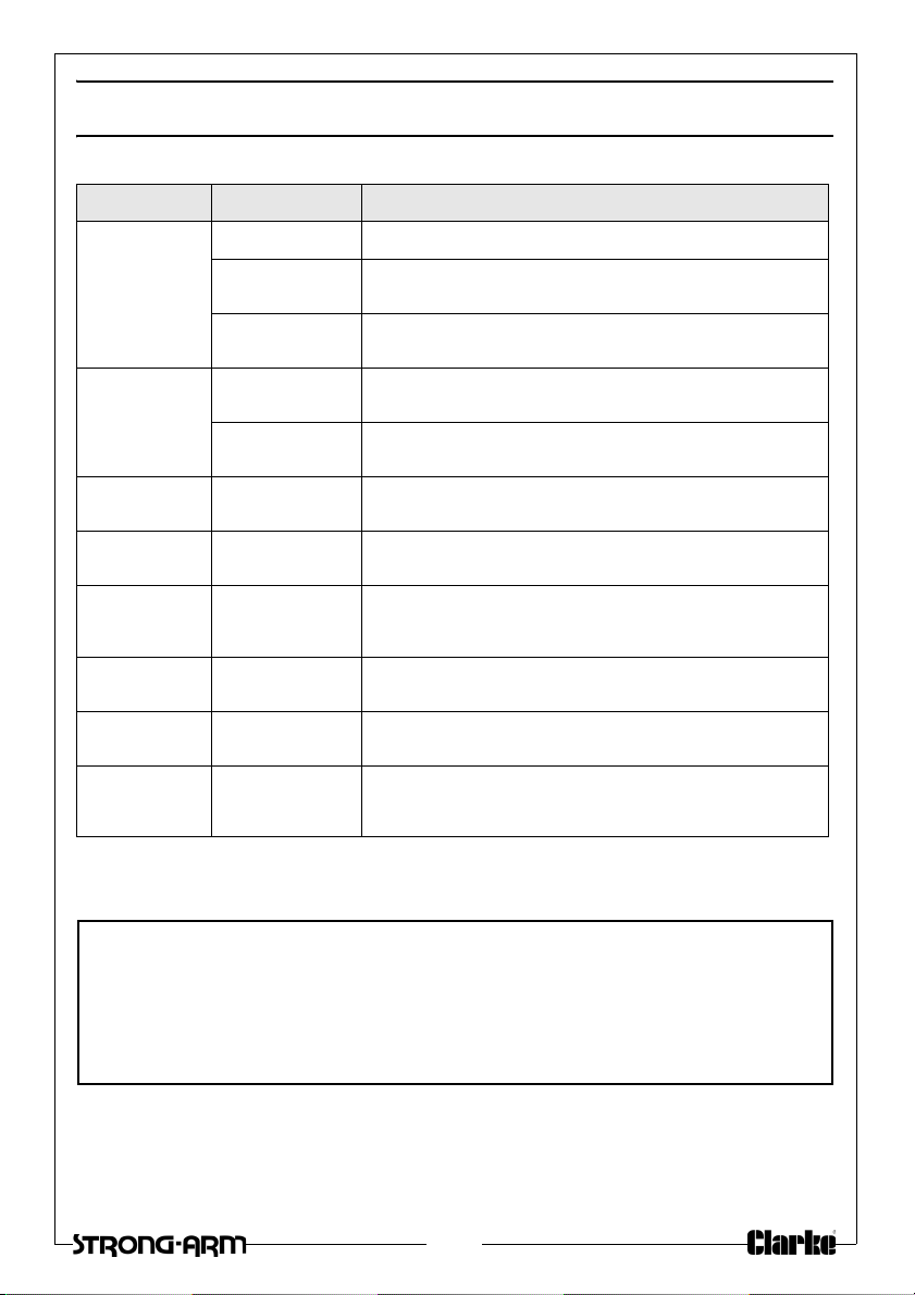
TROUBLESHOOTING
For Spare Parts and Servicing, please contact your nearest dealer, or
CLARKE International, on one of the following numbers.
PARTS & SERVICE TEL: 020 8988 7400
PARTS & SERVICE FAX: 020 8558 3622
PROBLEM CAUSE SOLUTION
Jack will not lift
the r
ated load
Jack lower
when under
lo
ad
Pump feels
ongy
Sp
Handle raises or
lies back under
f
load
Jack will not lift
full he
ight
Jack will not
lo
wer
completely
Low Oil Level See “Changing the oil” on page 8.
Release valve not
osed
cl
Air in the hydraulic
stem
sy
Release valve not
closed
Air in the hydraulic
stem
sy
Low Oil Level See “Changing the oil” on page 8.
Air in the hydraulic
sy
stem
Air in the hydraulic
system
Low Oil Level See “Changing the oil” on page 8.
Air in the hydraulic
stem
sy
Return spring may
be faulty
Turn the release knob fully clockwise
Bleed the system See page 6
Turn the release knob fully clockwise
Bleed the system See page 6
Bleed the system See page 6
Bleed the system See page 6
Bleed the system See page 6
See your Clarke Dealer
If any of these remedies fail to restore your jack, consult your Clarke dealer
9

EXPLODED DIAGRAM AND PARTS LIST
NO DESCRIPTION PART N O
1 Ram Assembly CTJ5GLB01
2 Front Wheel Assembly CTJ5GLB02
3 Rear Castor Assembly CTJ5GLB03
4 Saddle CTJ5GLB04
5 Rubber Pad CTJ5GLB05
6 Foot Pedal CTJ5GLB06
7 Extension Spring CTJ5GLB07
8 Handle Assembly CTJ5GLB08
9 Release Knob CTJ5GLB09
10 Universal Joint Assembly CTJ5GLB10
11 Pump Piston Assembly CTJ5GLB11
12 Filler Plug CTJ5GLB12
10

DECLARATION OF CONFORMITY
11

12
 Loading...