

Page 1
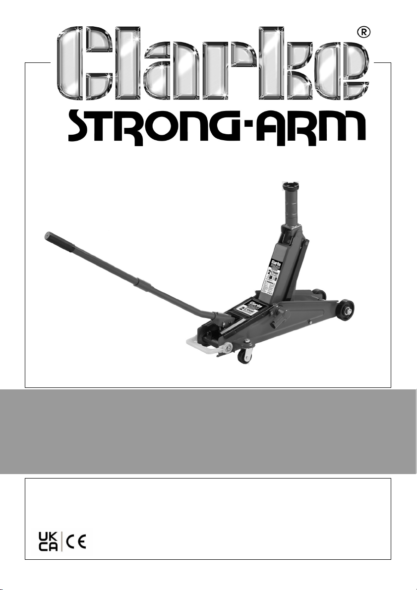
2.5T TROLLEY JACK WITH SUV SADDLE
MODEL NO: CTJ2500SUV
PART NO: 6601517
OPERATION & MAINTENANCE
INSTRUCTIONS
ORIGINAL INSTRUCTIONS GC03/23
Page 2
INTRODUCTION
Thank you for purchasing this CLARKE Trolley Jack.
Before attempting to use this product, please read this manual thoroughly and
follow the instructions carefully. In doing so you will ensure the safety of yourself
and that of others around you, and you can look forward to your purchase
giving you long and satisfactory service.
SPECIFICATIONS
Model number CTJ2500SUV
Weight 18.3 kg
Dimensions (L x W x H) without handle 622 x 242 x 158mm
Rated Load 2.5 tonne (2500kg)
Height of saddle from floor (minimum) 150 mm (245 with extension)
Max height of saddle with adaptor 530 mm
Max height of saddle without adaptor 435 mm
Pump oil capacity 120 ml
Number of strokes min-max height approx 45
Distance raised per stroke 6.5
GUARANTEE
This product is guaranteed against faulty manufacture for a period of 12
months from the date of purchase. Please keep your receipt which will be
required as proof of purchase.
This guarantee is invalid if the product is found to have been abused or
tampered with in any way, or not used for the purpose for which it was
intended.
Faulty goods should be returned to their place of purchase, no product can
be returned to us without prior permission.
This guarantee does not effect your statutory rights.
2
Page 3
SAFETY PRECAUTIONS
1. Read this instruction manual before use.
2. Only trained persons should operate this lifting equipment.
3. ALWAYS ensure that sufficient light is provided and that the work area is
kept clear of unrelated items.
4. ALWAYS inspect the jack before use. Make sure that all parts are in good
condition and operating smoothly and that no cracks or distortion is
apparent. If in doubt DO NOT use. Have the damaged parts replaced or
consult your CLARKE dealer.
5. The jack must be maintained and repaired by suitably qualified persons.
6. DO NOT make any modifications to this jack or adjust any valves.
7. DO NOT use the jack if an oil leak is apparent. Consult your CLARKE dealer.
8. DO NOT use to lift people and ensure that no-one is in the vehicle during
lifting.
9. NEVER exceed the rated load for the jack See “Specifications” on page 2.
Overloading can cause the jack to fail, resulting in personal injury.
10. Make sure that the jack is on a hard, level surface, and there is no possibility
of it slipping when under load.
11. Only use the jack on solid ground, preferably concrete. Avoid tarmac as
the jack could sink in.
12. Make sure the load is taken by the full saddle and that the lifting point on
the vehicle is of sufficient strength to support the weight.
13. ALWAYS use axle stands to stabilise the load once lifted.
14. Consult the vehicle handbook to determine the correct lifting points.
15. Ensure the vehicle is chocked and the handbrake applied before lifting.
16. NEVER work on or under a vehicle unless it is fully and adequately
supported.
17. NEVER rely upon the jack to hold the vehicle in position.
18. NEVER push a vehicle off the jack.
19. Ensure that all personnel are well clear of a load being raised or lowered.
20. Take care not to trap fingers in the moving parts.
21. Use only as a lifting device; do not use as a dolly to move a load.
3
Page 4
UNPACKING AND ASSEMBLY
Unpack the components and
remove packing materials. Check
that no damage has occurred during
transit and immediately advise the
CLARKE dealer where you purchased
the product of any deficiency.
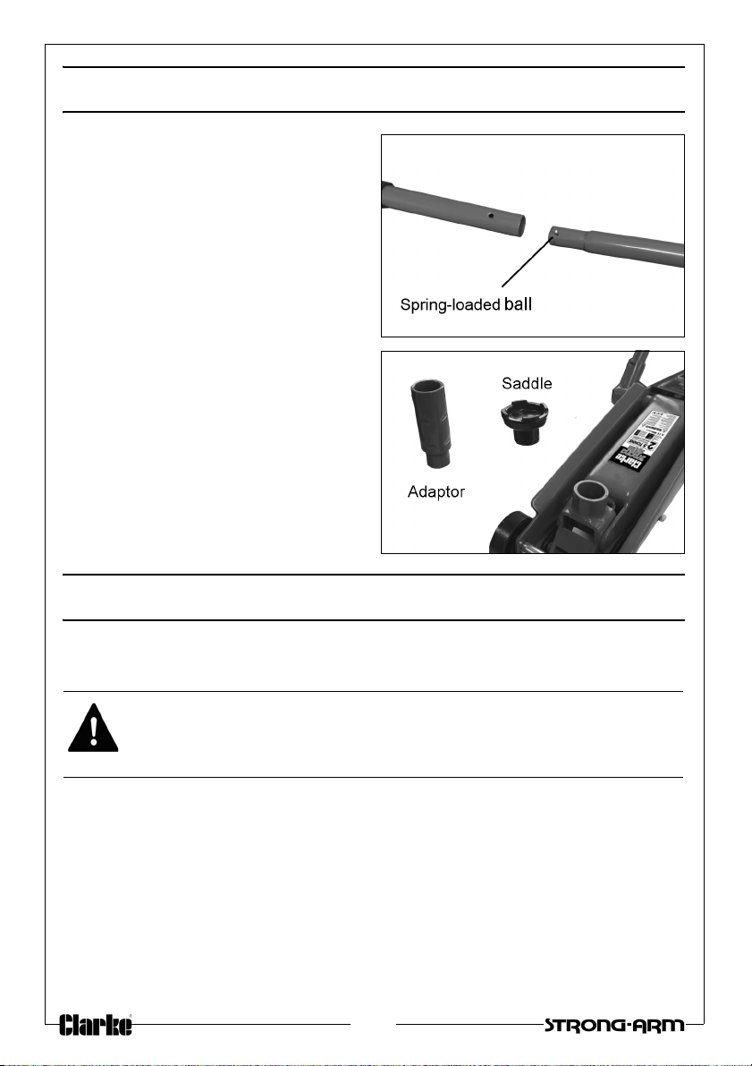
1. Connect the two halves of the
handle tog
together with the spring-loaded
ball.
2. Fit the adaptor into the socket if
an SUV is the vehicle to be lifted.
3. Add the saddle either to the lifting
ar
m or to the top of the adaptor
as required.
ether and clip
OPERATION
Before use, inspect the jack for oil leaks or any other sign of damage. Should
any be apparent, have the jack repaired by a qualified technician.
WARNING: NEVER WORK ON THE VEHICLE WHEN SUPPORTED ONLY BY A
JACK WHICH IS A HIGHLY DANGEROUS PRACTICE. THE VEHICLE MUST BE
SUPPORTED ON AXLE STANDS OR SUITABLE SUPPORTS, BENEATH THE
CORRECT JACKING/SUPPORT POINTS.
1. Ensure the vehicle to be raised is stable
wheels chocked.
2. Position the jack so that the saddle is directly beneath the lifting point. In
the case of high riding SUVs, insert the adaptor between the jack and the
saddle, seating both items in the socket provided.
• Consult the vehicle handbook to determine suitable lifting points.
3. Engage the end of the handle with the jack control valve. Twist the handle
clockwise
to close the control valve.
and on firm level ground with the
4
Page 5
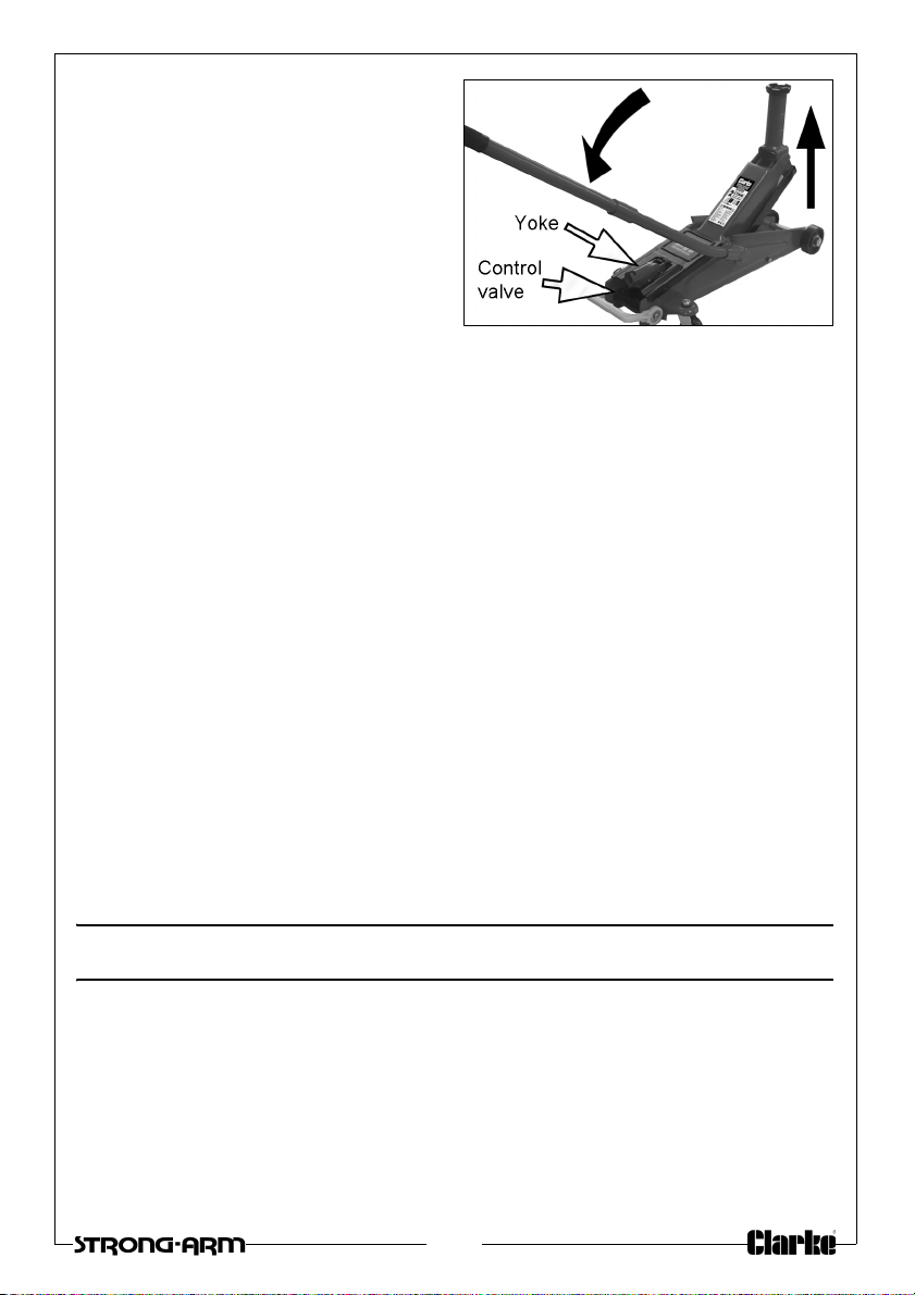
4. Insert the handle into the quick lift
operating arm on the side of the
jack. Depress fully down to quickly
raise the arm to the height
needed for a high riding SUV.
5. Next, insert the handle into the
oke and pump the handle to
y
raise the saddle until it reaches
the jacking point.
6. Take care that no obstruction
prevents a clean lift. Keep all personnel at a safe distance before lifting the
vehicle.
NOTE: T
7. Position axle stands directly beneath suitable supporting points under the
8. Very gently twist the handle anticlockw
9. To stop it lowering at any point, turn the handle clockwise again.
10. Carefully lower the vehicle onto the axle stand, checking constantly,
NOTE: Ensure this operation is carried out under complete control. DO
11. Completely remove the j
12. Store the handle in the socket on the side of the jack.
he jack may move slightly during operation. It is important
therefore, that the floor is free from debris.
vehicle
ise to open the control valve and
lower the vehicle onto the axle stands. ALWAYS avoid a rapid descent by
turning the handle slowly.
prefe
rably with an assistant, that the vehicles jacking point rests snugly and
cleanly on the axle stand, and that the stand is stable before the weight is
taken.
NOT allow the load to drop suddenly as this could damage
internal parts or the vehicle.
ack from the vehicle.
MAINTENANCE
GENERAL CARE
1. Periodically lubricate the hinges, front wheels & rear castors with light oil.
2. In the event of damage or broken components, replacements are
available from CLARKE Par
ts & Service.
5
Page 6
PURGING AIR FROM THE SYSTEM
If air bubbles become trapped inside
the hydraulic components, the
efficiency of the jack will be
reduced. If the air cannot be
dispersed just by pumping the handle
with the valve open, it can be
purged from the system as follows.
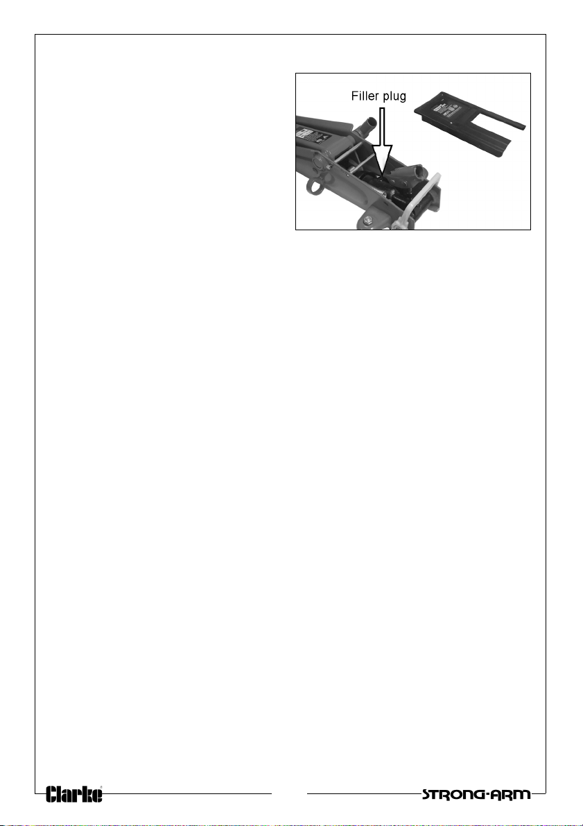
1. Turn the control valve counterclockwise, relieving the pressure
within the jack, then prise off the
cover plate & unscrew the filler
plug.
• A broad-bladed screwdriver is required for the plug.
2. Pump the handle several times to purge air from the system.
3. Replace the oil filler plug, then turn the control valve clockwise and test the
jack. If efficiency is still low, check the oil level as below.
CHECKING THE OIL LEVEL
If the jack has been stored for long periods, check for oil leaks before use. If
necessary, check the oil level as follows:
1. Ensure the jack is fully lowered by turning the control valve anticlockwise.
2. Remove the cover plate and the oil filler plug.
• The oil should be almost level with the bottom of the oil filler hole.
• It can be topped up using CLARKE Hydraulic Oil (p/no 3050830 for 1L).
3. Purge any air from the system and replace the oil filler plug.
4. Dispose of any old/spilled oil appropriately and wipe up any spillage.
STORAGE
1. Store in a dry place with the ram fully lowered. For servicing, contact your
CLARKE dealer or CLARKE International Service Department.
ENVIRONMENTAL PROTECTION
One of the most damaging sources of environmental pollution is oil products.
NEVER throw away used hydraulic oil with domestic refuse or flush it down a
sink or drain. Collect any hydraulic oil in a leak proof container and take it to
your local waste disposal site.
If disposing of this product or any damaged components, DO NOT dispose of
with general waste. This product contains valuable raw materials and should
be taken to your local civic amenity site for recycling of metal products.
6
Page 7
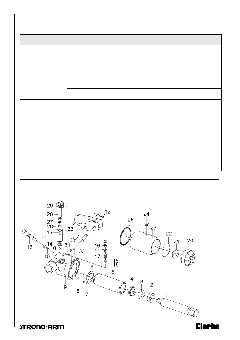
TROUBLESHOOTING
PROBLEM CAUSE SOLUTION
Jack will not lift
the rated load
Jack lower when
under load
Pump feels
spongy
Jack will not lift
full height
Jack will not
lower fully
If any of these actions fail to restore function, consult your Clarke dealer.
Low oil level See ‘Checking the Oil Level‘on page6
Valve not closed Turn the release knob fully clockwise
Air in the system Purge the system as on page 6.
Valve not fully closed Turn the release knob fully clockwise
Air in the system Purge the system as on page 6
Low oil level See ‘Checking the Oil Level‘on page6
Air in the system Purge the system as on page 6.
Low oil level See ‘Checking the Oil Level‘on page6
Air in the system Purge the system as on page 6.
Return spring may
be faulty
Return to your Clarke dealer for repair.
COMPONENT PARTS - HYDRAULIC RAM
7
Page 8
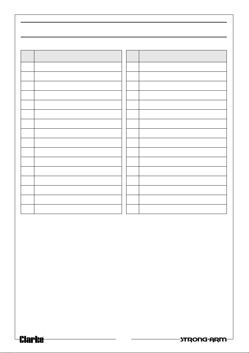
COMPONENT PARTS - HYDRAULIC RAM
No Description No Description
1 Piston 17 Valve spring
2 Piston head 18 Spring seat
3 O-ring 19 Steel ball
4 Y-ring seal 20 Top cup
5 Cylinder 21 O-ring
6 Cylinder gasket 22 Seal
7 Filter oil tube 23 Cylinder
8 Steel ball 24 Oil plug
9 Val v e bod y 25 Cylinder oil seal
10 Steel ball 26 O-ring
11 O-ring 27 Retaining ring
12 Cotter pin 28 Pump operating piston
13 Oil return valve stem 29 Piston connector
14 Pump core gasket 30 Hinge pin-small
15 Pump body 31 Hinge pin-large
16 Regulator screw 32 Handle yoke
8
Page 9
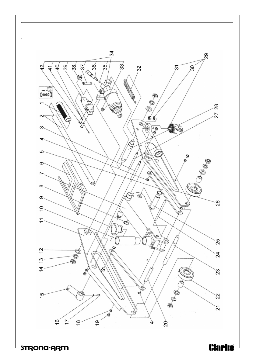
COMPONENT PARTS - GENERAL ASSEMBLY
9
Page 10
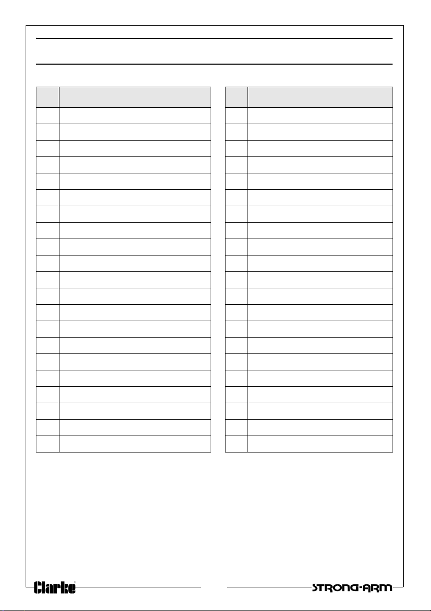
COMPONENT PARTS (GENERAL ASSEMBLY)
No Description No Description
1 Handle cover 22 Front wheel
2 Handle 23 Front axle
3 Support shaft 24 Tie rod
4 Circlip 13mm 25 Main hinge pin
5 Connecting rod 26 Left side plate
6 Cover plate 27 Spacer rod
7 Lifting arm assembly 28 Supporting shaft
8 Circlip 22mm 29 Rear caster
9 Saddle 30 Retaining washer 10mm
10 Saddle adaptor (SUV) 31 Nut M10
11 Right side plate 32 Return spring
12 Washer 16mmm 33 Oil plug
13 Retaining washer 16mm 34 Hydraulic ram assembly
14 Nut M16 35 Steel ball
15 Handle socket 36 Valv e pi sto n
16 Retaining washer 5mm 37 Operating piston
17 Philips head screw 38 Retaining clip
18 Retaining washer 8mm 39 Handle yoke
19 Nut M8 40 Hinge pin (small)
20 Pin 41 Cotter pin
21 Front wheel bush 42 Hinge pin (large)
10
Page 11
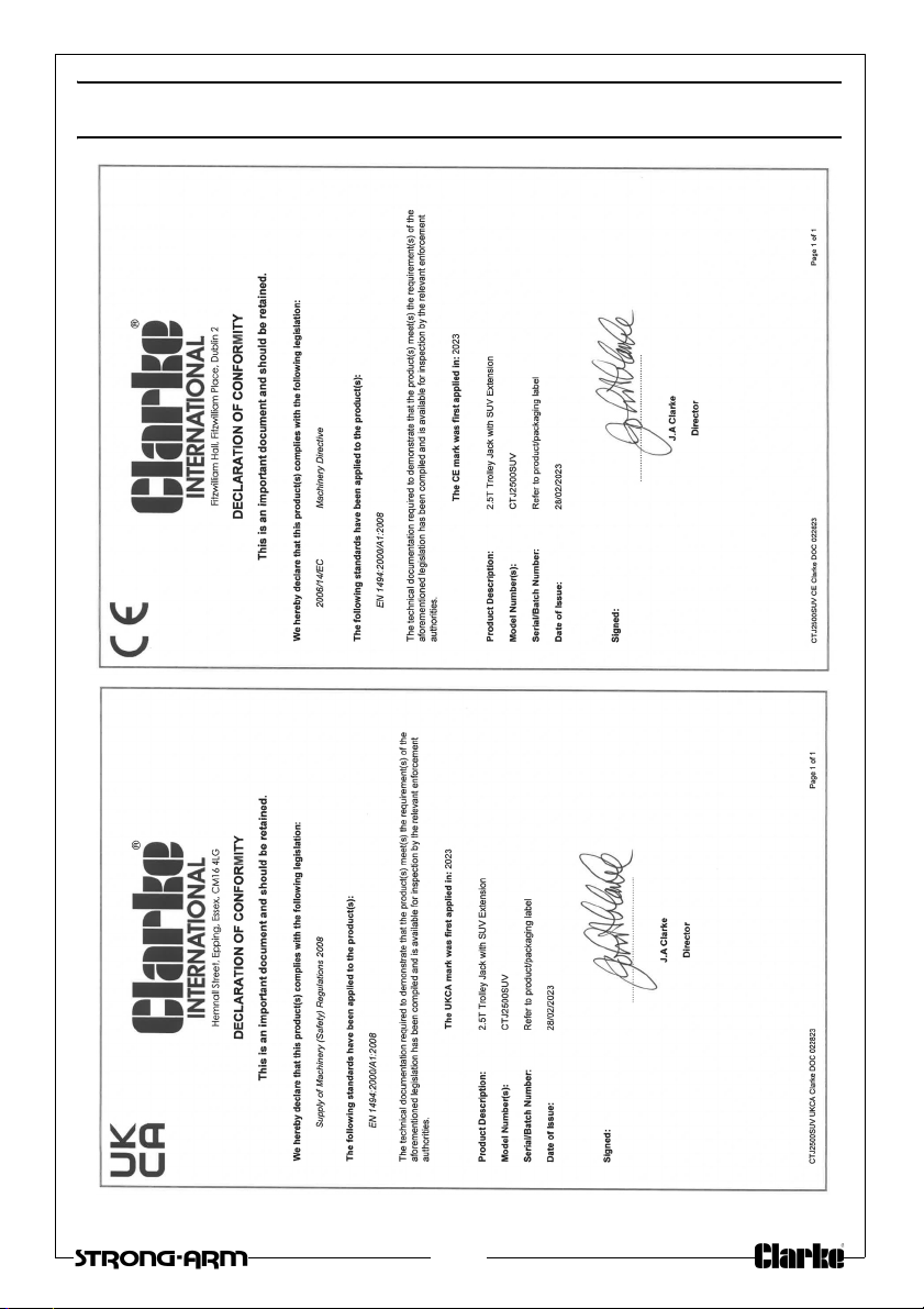
DECLARATIONS OF CONFORMITY
11
Page 12
 Loading...