

Page 1
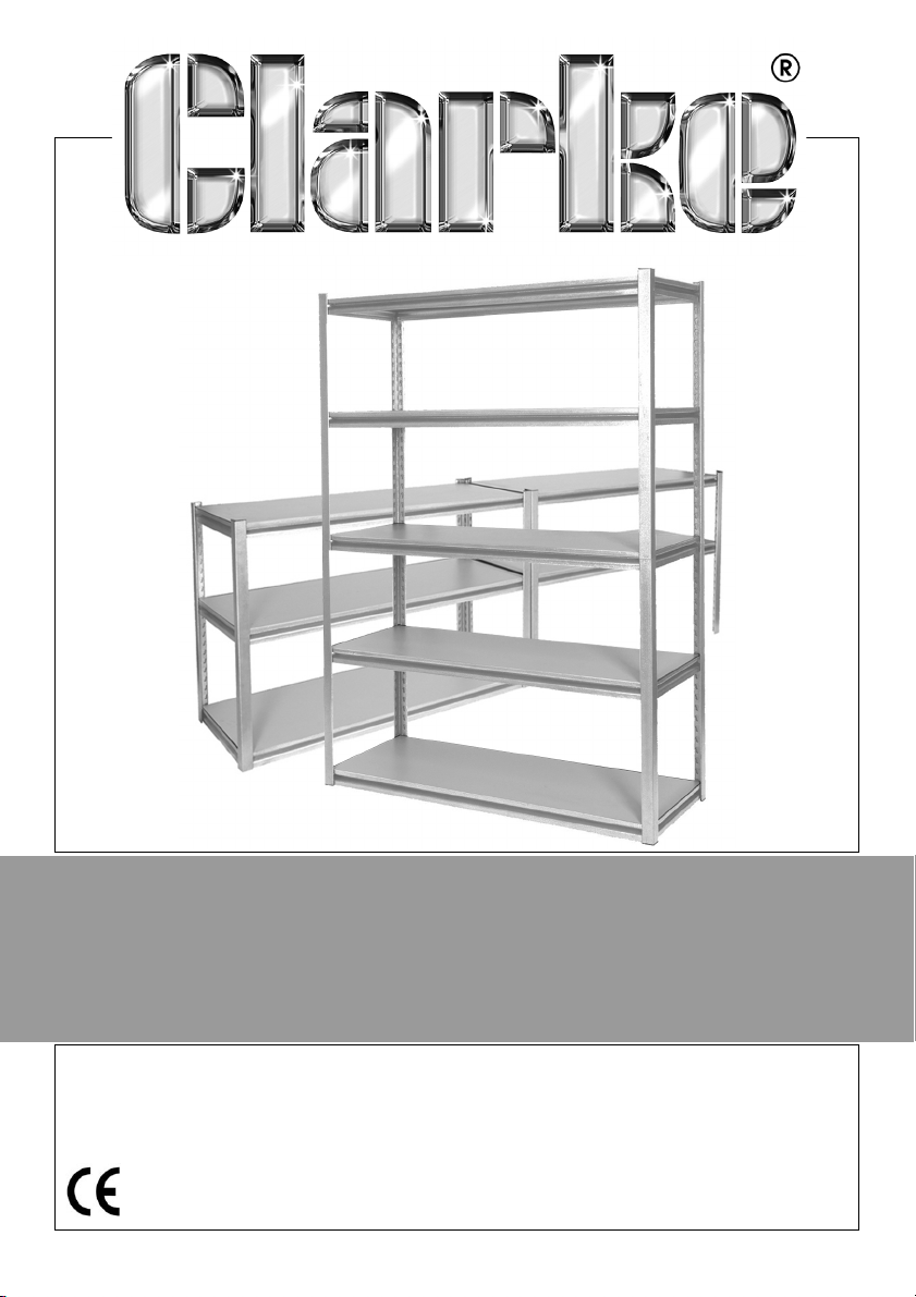
5-SHELF BOLTLESS SHELVING UNITS
MODEL NO: CS5265S, CS5265RP & CS5265BP
PART NO: 6600640, 6600645 & 6600650
ASSEMBLY INSTRUCTIONS
GC0115
Page 2

INTRODUCTION
Thank you for purchasing this CLARKE product.
Before attempting to use this product, please read this manual thoroughly and
follow the instructions carefully. In doing so you will ensure the safety of yourself
and that of others around you, and you can look forward to your purchase
giving you long and satisfactory service.
GUARANTEE
This product is guaranteed against faulty manufacture for a period of 12
months from the date of purchase. Please keep your receipt which will be
required as proof of purchase.
This guarantee is invalid if the product is found to have been abused or
tampered with in any way, or not used for the purpose for which it was
intended.
Faulty goods should be returned to their place of purchase, no product can
be returned to us without prior permission. This guarantee does not effect your
statutory rights.
GENERAL SAFETY RULES
1. Always maintain the equipment in good condition for the best/safest
performance.
2. Never exceed the maximum load for these units.
3. Never use these units if they are damaged.
4. Always load small, stable items on the top shelves, heavier and bulky items
should be stored on the lower shelves.
Please keep these instructions in a safe place for future reference.
ENVIRONMENTAL PROTECTION
Do not dispose of this product or damaged parts with general household
waste. All tools, accessories and packaging no longer required should be
sorted, taken to a recycling centre and disposed of appropriately.
2
Parts & Service: 020 8988 7400 / E-mail: [email protected] or [email protected]
Page 3
INVENTORY
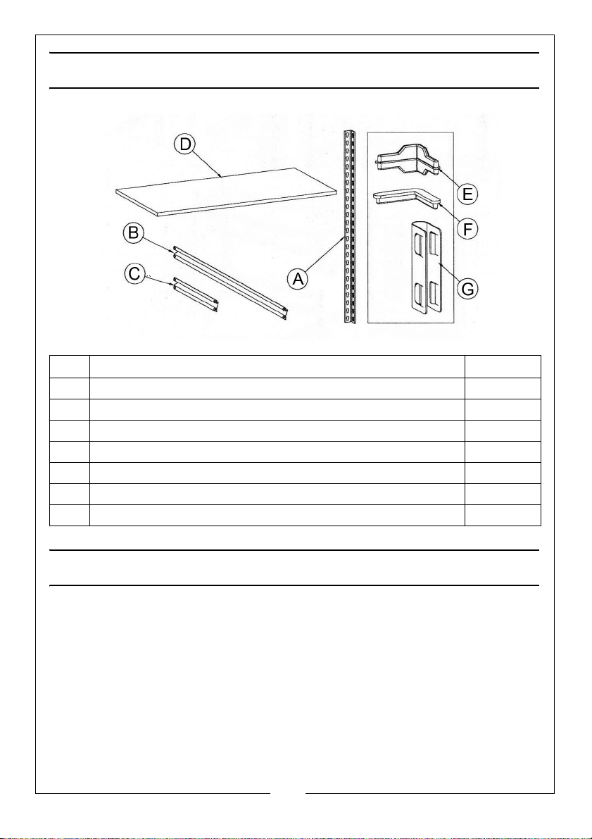
No Description Quantity
ACorner Post 8
B Long Beam 10
C Short Beam 10
D Shelf 5
EPost Insert 4
FEnd Cap 8
G Corner Post Joining Clip 2
ASSEMBLY ADVICE
1. Assemble on a strong, level surface. Avoid assembly on a domestic carpet.
2. Use a cloth or softwood block to protect the surface finish of the product
when using a mallet. Strike the flat surface of each beam to prevent
damage to the beam.
3. Always ensure that the rivets sit at the bottom of the keyhole slots.
4. It is recommended that the assembly should be done by two persons.
5. The shelving unit is not recommended for outdoor use.
3
Parts & Service: 020 8988 7400 / E-mail: [email protected] or [email protected]
Page 4
ASSEMBLY INSTRUCTIONS
TOOLS REQUIRED
Rubber mallet or hammer
Protective cloth/wood block
OPTION 1 - ASSEMBLED AS STORAGE RACKING
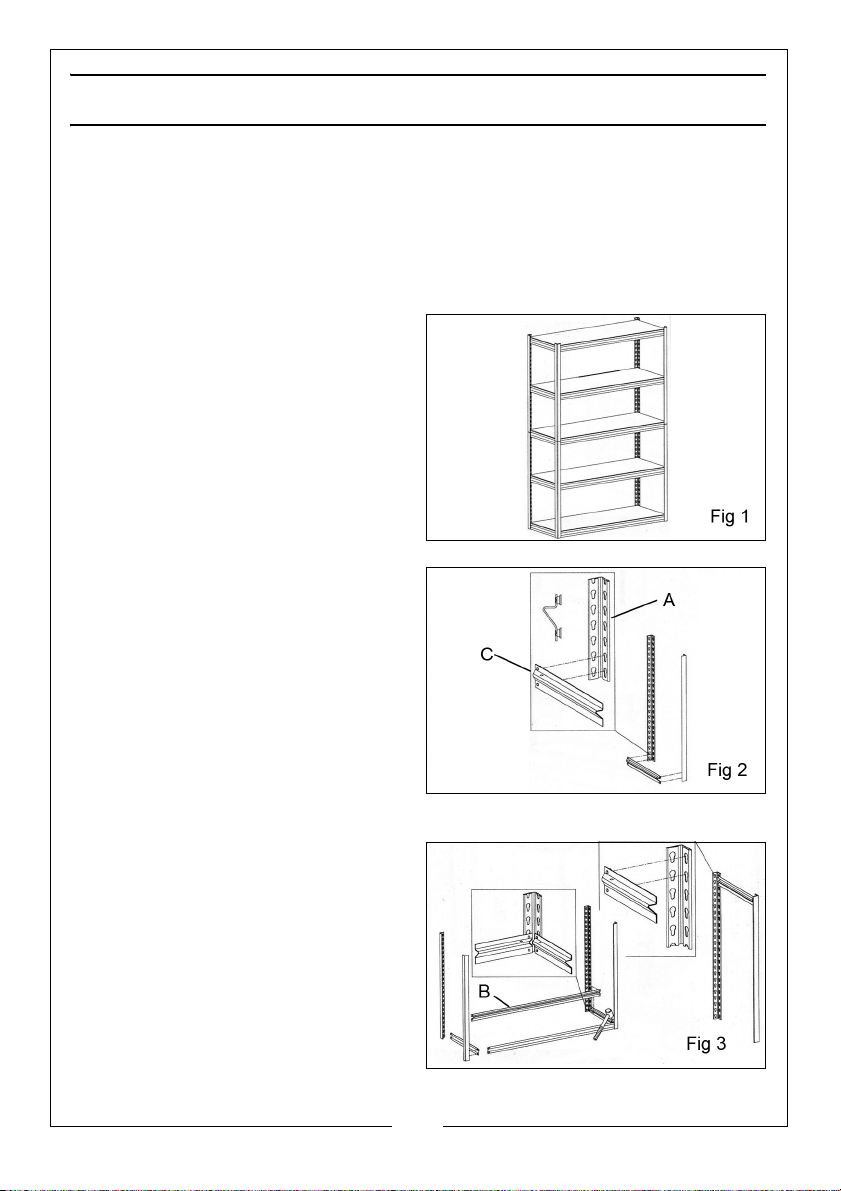
1. The storage racking configuration
is shown in Fig 1.
2. Create an end assembly by fitting
a short beam (C) into the lowest
keyholes of two corner posts (A).
• Drive the rivets to the bottom of
the keyholes by tapping the beam
near the joint with a rubber mallet
to lock the pieces together. Use a
cloth or softwood block to protect
the surface finish.
• Ensure all beams are installed with
the flat (shelf-bearing) surface uppermost.
3. Create a second end assembly.
4. Join the two end assemblies
together with two long beams (B)
as in Fig 3.
4
Parts & Service: 020 8988 7400 / E-mail: [email protected] or [email protected]
Page 5
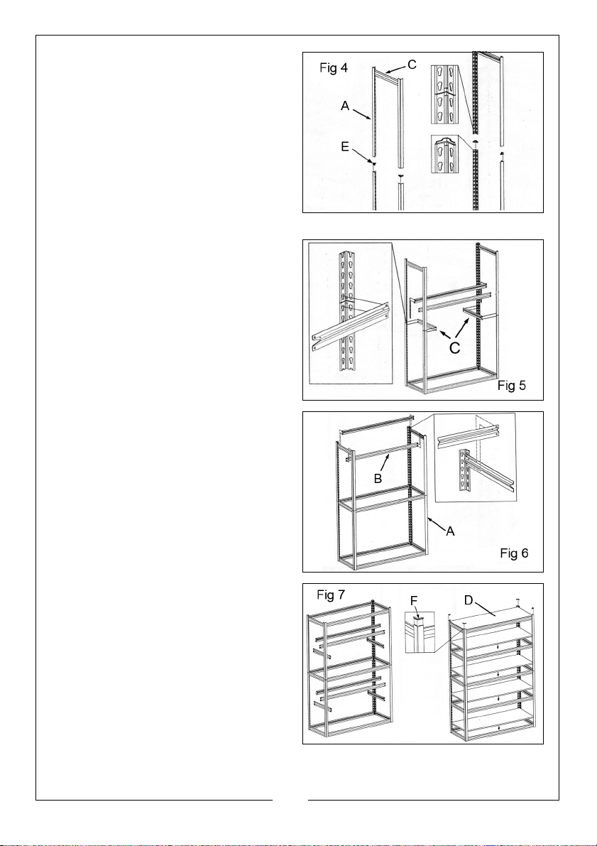
5. Use a short beam (C) in the top
holes to join two corner posts and
create an upper end assembly as
shown in Fig 4.
6. Repeat for the opposite upper end
assembly.
7. Fit post inserts (E) into the corner
posts (A) of the lower assembly.
8. Fit both upper end assemblies onto
the post inserts (E).
9. Use a short beam (C) to join the
upper and lower assemblies
together at each end as shown in
Fig 5. Repeat with the long beams
at each side.
• The beams must span the upper
and lower assemblies.
10. Add long beams (B) to the top
keyholes of the corner posts (A) as
shown in Fig 6.
11. Connect the remaining beams as
required to create two additional
shelves.
12. Lay the shelf panels (D) into
position.
13. Insert the post caps (F) into the top
of each corner post (A).
5
Parts & Service: 020 8988 7400 / E-mail: [email protected] or [email protected]
Page 6
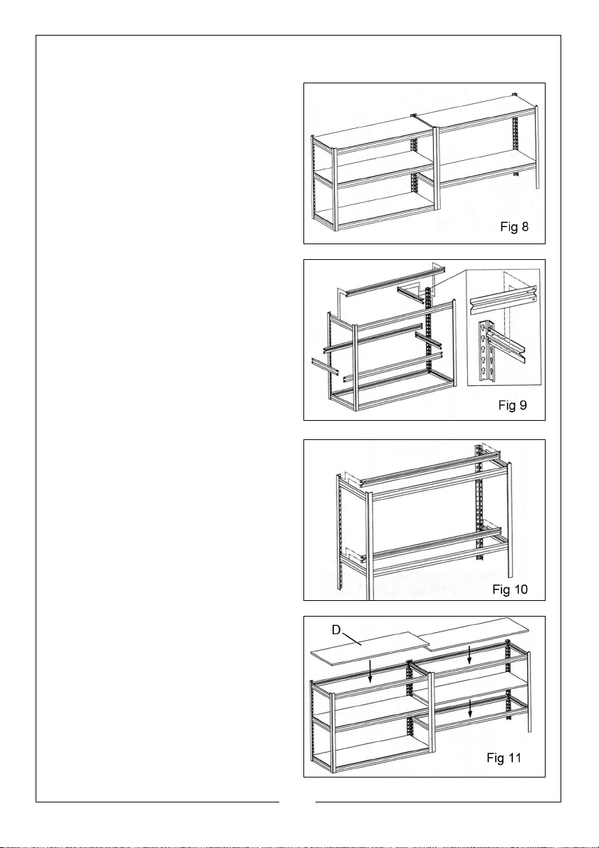
OPTION 2 - ASSEMBLED AS A WORKBENCH
1. An alternative workbench
configuration is shown in Fig 8.
• The two units can be used as freestanding benches or joined
together, in-line or at right angles.
2. Create two end frame assemblies
and join together using the steps
on page 4.
3. Add additional beams to create a
center shelf at the required level as
in Fig 9.
4. Assemble the second unit with the
lower beams typically installed at
the 7th/8th keyholes from the
bottom as shown in Fig 10.
5. Complete the second bench as
shown in Fig 11.
6. Lay the shelves (D) in position.
6
Parts & Service: 020 8988 7400 / E-mail: [email protected] or [email protected]
Page 7
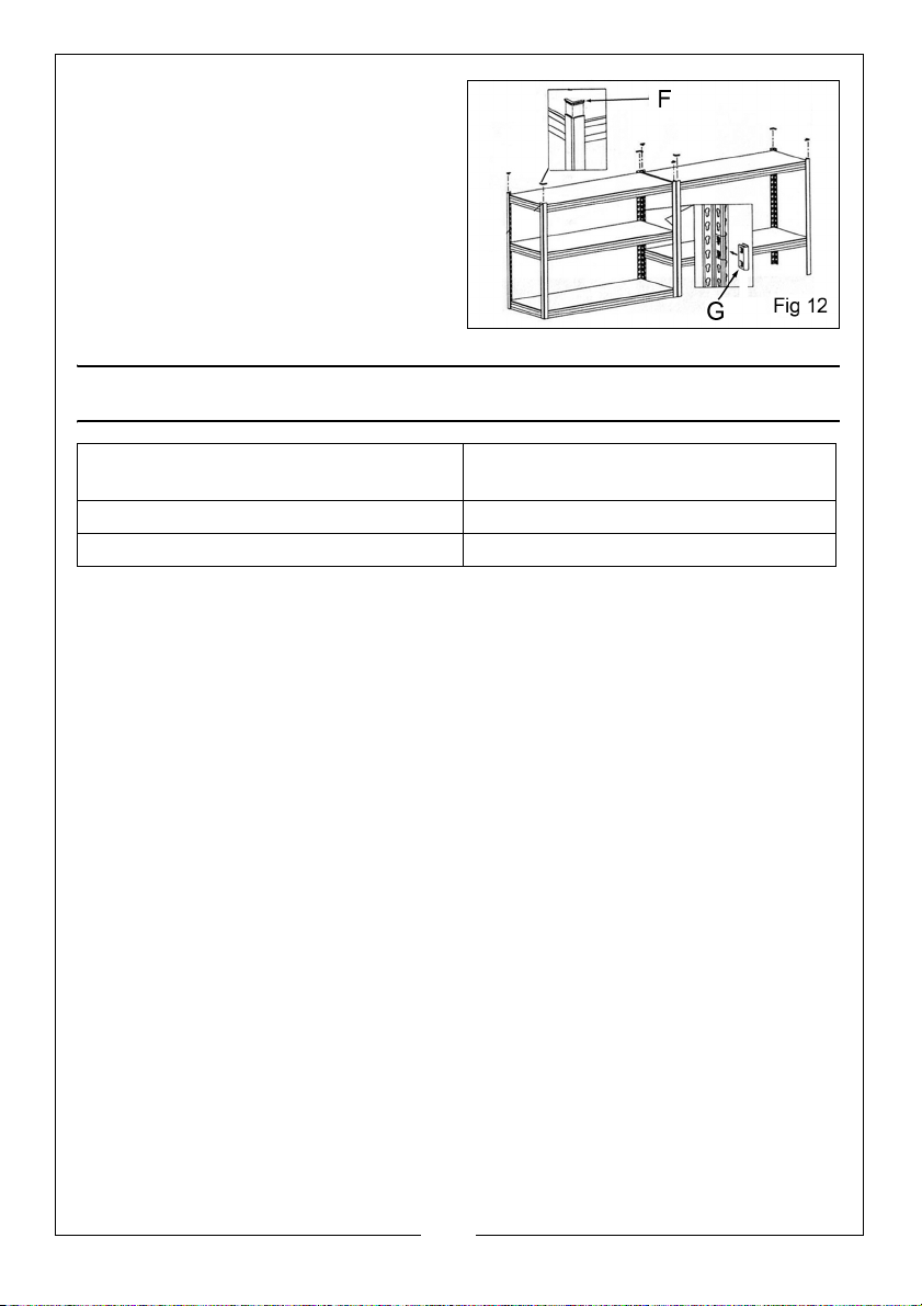
7. Insert the post caps (F) to the top
of the corner posts.
8. To connect the bench units draw
the assemblies together and use
Post Joining Clips (G) to tightly
clamp the corner posts together.
• A screwdriver can be used to prize
off the clips if required.
SPECIFICATION
Dimensions (W x D x H) Shelving Unit 1220 x 460 x 1830 mm
Workbench 2440 x 460 x 915 mm
Weight (Empty) 31 kg
Maximum Rated Load 265 kg per shelf (evenly distributed)
7
Parts & Service: 020 8988 7400 / E-mail: [email protected] or [email protected]
Page 8

 Loading...