

Page 1
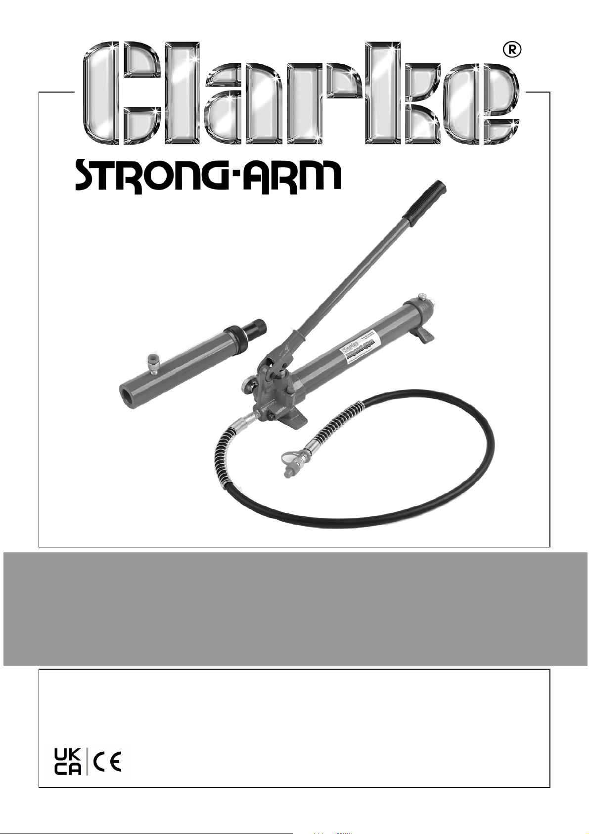
HYDRAULIC PUMP, RAM & HOSE
MODEL NO: CS10PRH
PART NO: 7617020
OPERATION & MAINTENANCE
INSTRUCTIONS
ORIGINAL INSTRUCTIONS DL0922 - Rev 2
Page 2
INTRODUCTION
Thank you for purchasing this CLARKE hydraulic pump, ram & hose. This
manual covers the ram and hose which can be used in conjunction with
components from the 10 Tonne body repair kits type CS10BRK/CS10SBRK.
Body repair kits are designed for bending chassis frames and vehicle body
panels. In most cases, the equipment will only return the vehicle body parts to
approximately their original position. Additional work will be required to
complete the repair. The hydraulic ram and hose must be connected to the
pump unit and suitable accessories. It requires a solid immovable base,
directly in line with the damaged area.
Before attempting to use this product, please read this manual thoroughly and
follow the instructions carefully. In doing so you will ensure the safety of yourself
and that of others around you, and you can look forward to your purchase
giving you long and satisfactory service.
SPECIFICATIONS
CS10PRH
Hose dimensions (L x O/D) 1350 x 17 mm
Hose max operating pressure 140 psi
Ram unit length (ret/ext) 370 x 512 mm
Ram rated operating force 10 Tonne
Ram piston stroke 142 mm
Pump oil capacity 500 g
Pump rated operating pressure 62 Mpa
Pressure relief valve operating pressure 10 Tonne
2
Page 3
SAFETY PRECAUTIONS
WARNING: THE OPERATOR MUST FOLLOW ALL INSTRUCTIONS WITHIN THIS
INSTRUCTION BOOKLET
WORK AREA
1. Keep the work area clean and well lit. Cluttered and dark areas invite
accidents.
2. Keep children and bystanders away while working. Distractions can cause
you to lose control and bystanders should be kept at a safe distance from
the working area especially when work is in progress.
PERSONAL SAFETY
1. Stay alert, watch what you are doing and use common sense when using
this equipment. Do not operate this equipment when you are tired, ill or
under the influence of alcohol, drugs or medication.
2. Do not over-reach. Keep your proper footing and balance at all times. This
enables better control of the equipment in unexpected situations.
3. Concentrate on the job in hand, no matter how trivial it may seem. Be
aware that accidents are caused by carelessness due to familiarity.
4. Do not wear loose clothing or jewelry which may get caught in moving
parts. Wear protective hair covering to contain long hair. For best footing,
wear rubber soled footwear. Keep floor clear of oil, scrap wood, etc.
5. Before working on a vehicle with this repair kit, ensure the vehicle is well
supported and completely stable.
6. Remember that during body repair, there is always the possibility of a fixture
slipping or a body part failing, which could cause the vehicle to jolt
suddenly. If the vehicle is not adequately supported, it could fall with
possibly serious consequences.
7. Never use an additional extension handle to operate the pump.
8. Never modify this equipment in any way.
9. Check the equipment for damage before use. Any damaged part should
be discarded and replaced. Check for alignment of parts, breakage of
parts, and any other condition that may affect the operation. Any
damage should be properly repaired or the part replaced. If in doubt, DO
NOT use. Consult your local Clarke dealer.
10. Store out of the reach of children and do not allow persons unfamiliar with
these instructions to use this product.
3
Page 4
ASSEMBLY
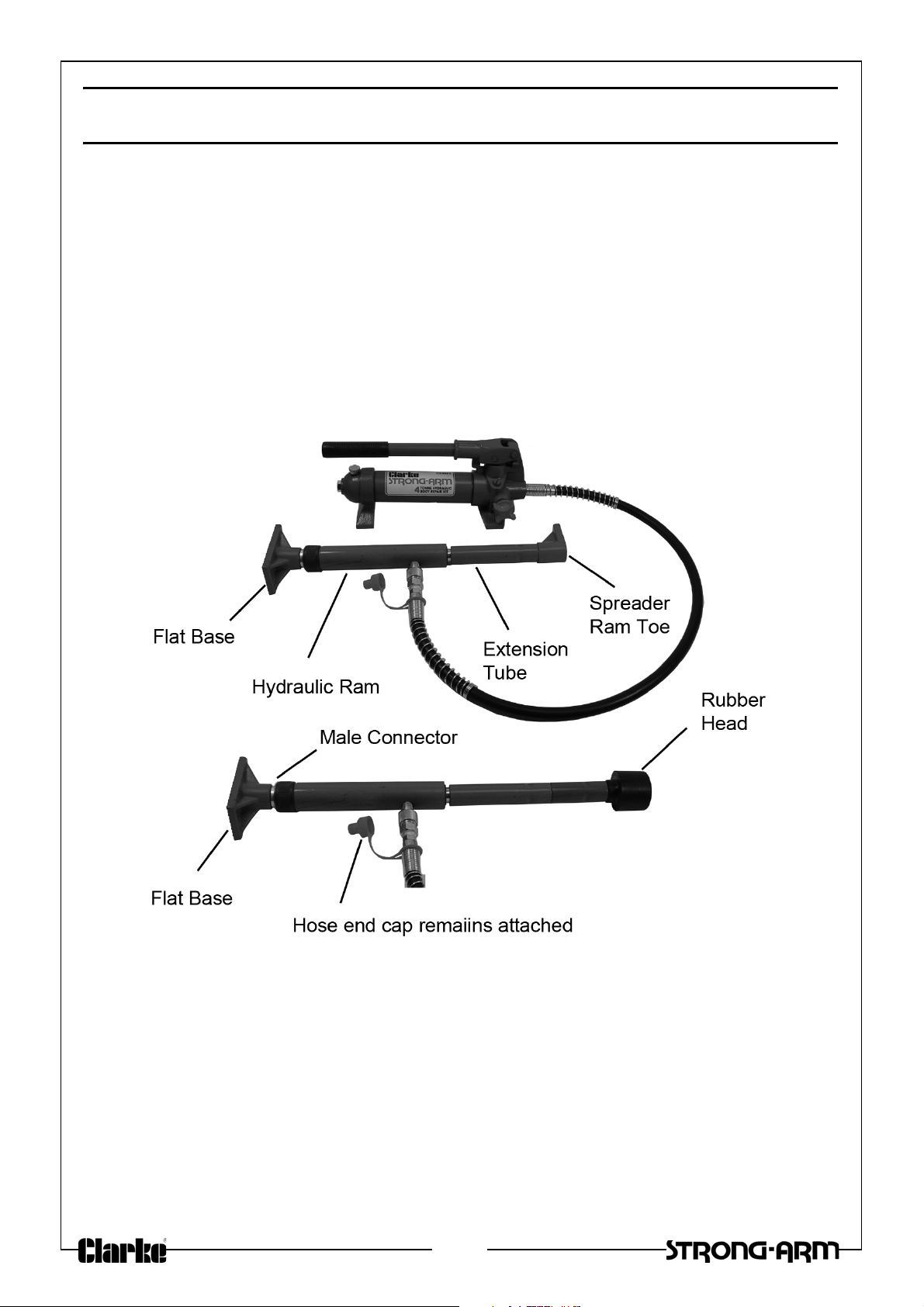
When assembling the Hydraulic Ram, Pump unit and attachments, unscrew
and retain the plastic end plugs on the connections for future use. Ensure the
hydraulic hose is tightly screwed to the connection.
1. Screw the Pump Handle into the socket in the pump unit.
2. Connect the pump to the ram using the hose.
3. Fit a Flat Base to the static end of the ram using a male connector.
Connect other attachments to the moving end of the ram as required.
• Various combinations of extension tubes and attachments can be
assembled as shown, according to the distance between the work
surface and the supporting frame.
For full instructions including the use of the various attachment available, refer
to the manual supplied with the CS10BRK/CS10SBRK Body Repair Kits.
4
Page 5
OPERATION
Assemble the components including a flat base and as many extension tubes
as required.
CAUTION: NOTE THAT WHEN ADDING FURTHER EXTENSION TUBES, THE
MAXIMUM RATED LOAD IS REDUCED. (SEE WARNING LABEL)
1. Connect the Hydraulic Ram or Hydraulic Spreader to the connecting hose
using the screw-on hose connector. Use the male connector to join the
ram to your selected attachment or any extension tube.
2. To operate the Hydraulic Pump, position it on a stable, level surface close
to the damaged area. Close the Release Valve by turning it clockwise and
pump the handle to create pressure.
3. Turn the Release Valve counter-clockwise to release the pressure.
• The pump may be positioned horizontally or vertically. When using
the Hydraulic Ram in a vertical position, always keep the hose end
facing downward.
CAUTION: NEVER OVERLOAD THE RAM BEYOND ITS CAPACITY. ENSURE
THE BEARING POINT IS STABLE AND PROPERLY CENTRED ABOVE THE RAM.
NEVER OVERLOAD THE ATTACHED COMPONENTS BEYOND THEIR RATED
CAPACITIES AS STATED IN THE SPECIFICATION.
Always apply the load slowly to be sure that everything is secure. Take care
that the load is always in line with the ram.
USING THE RAM
1. Determine in which direction the target area needs to be pushed.
2. Remove any obstructions that are in the way and could be damaged.
3. Connect a Flat Base to the stationary side of the Hydraulic Ram and
connect the appropriate attachment to the working end of the Ram.
NOTE: When repairing larger body panel dents such as a dented door,
wing or quarter panel, the correct pushing attachment will be
the Rubber Head.
4. Position the Hydraulic Ram so that the flat base is resting against a frame
member opposite the damaged area. It must be in line with the direction
in which the damaged area needs to be pushed and have enough
support that only the damaged area will be displaced by the ram pressure.
• Use soft pads or wooden supports where necessary to protect the
body.
5
Page 6
5. Aim the pushing end towards the damaged area and slowly apply
pressure with the pump.
6. Once contact is established at each end, keep as well clear as practical
and slowly apply pressure to the damaged area until the desired
correction has been made.
CAUTION: KEEP HANDS AWAY FROM CONTACT AREAS AND TIGHT
SPACES IN CASE THE COMPONENTS SHOULD SLIP AND CAUSE INJURY.
7. When the damaged area has been bent to the desired position, slowly turn
the release valve on the pump unit in a counterclockwise direction to
release hydraulic pressure before removing the Ram.
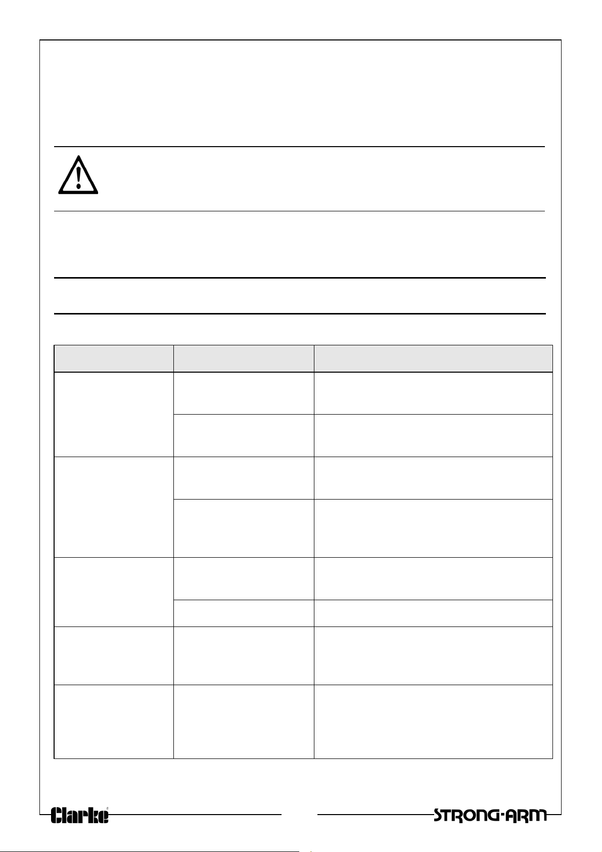
FAULTFINDING
PROBLEM CAUSE SOLUTION
Ram does not
operate when
handle is
pumped
Ram will not hold
load.
Ram reluctant to
lower when load
removed.
Ram will not
extend to full
range of stroke
Release valve not
tightly closed.
Air trapped in system Purge air from the system by
Release valve not
tightly closed.
Malfunction in pump
such as dirt inside
valve mechanism.
Oil reservoir
overfilled.
Piston binding. Clean and lubricate moving parts.
Low oil level. Add hydraulic oil to the reservoir.
Firmly close the release valve.
pumping the operating handle.
Firmly close the release valve.
Return pump to dealer for overhaul.
Drain oil to the correct level
Ram tries to tilt to
one side.
Poor positioning of
the footing
Stop work and reposition ram and
base, ensuring it is well supported
and as close to the perpendicular to
the repair as possible.
6
Page 7
MAINTENANCE
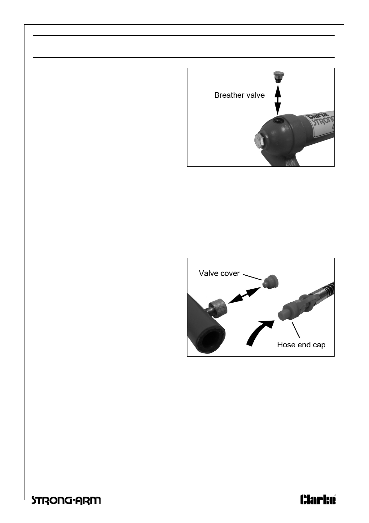
If the pump has been stored for long
periods, check the oil level before
use. Stand the pump on a level
surface and remove the breather
valve on the oil reservoir. If necessary,
top up via the breather valve which is
then screwed on finger tight.
NOTE: Only unscrew this when the
system is not under pressure.
The oil level should be near the
bottom of the opening. If required, oil can be topped top using Clarke
Hydraulic Oil. (part no. 3050830 for 1 litre).
After extensive use, the hydraulic oil should be replaced to ensure longer
equipment life. Do not overfill, or the piston rod will be unable to move freely.
Replace the breather valve after re-filling. The required oil volume is 500 ml +
5ml.
STORAGE
After use, screw the valve cover on
to the pump to keep the connection
clear of dust and dirt and cover the
hydraulic hose end with the plastic
cap.
When not in use, the pump should be
stored with the release valve open.
Store all the equipment in its case in a
clean, dry environment protected
from the weather.
ENVIRONMENTAL PROTECTION
One of the most damaging sources of environmental pollution is oil products.
Never throw away used hydraulic oil with domestic refuse or flush it down a
sink or drain. Collect any hydraulic oil in a leak proof container and take it to
your local waste disposal site.
If disposing of this product or any damaged components, do not dispose of
with general waste. This product contains valuable raw materials and should
be taken to your local civic amenity site for recycling of metal products.
7
Page 8
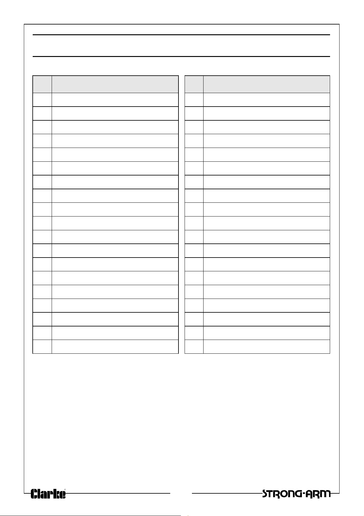
PUMP COMPONENT PARTS
No Description No Description
1 Valve Body 20 Steel Ball
2 Oil Filter 21 Ball Cup
3 O-ring 22 Spring
4 Oil Reservoir 23 Screw
5 Sealing Ring 24 Screw Protector
6 Thumb Nut 25 O-ring
7 Sealing Ring 26 Nylon Sealing Ring
8Tie Rod 27Screw
9 O-ring 28 O-ring Seal
10 Pump Foot 29 Piston
11 Hydraulic Hose 30 Hinge Pin
12 Coupling 31 Circlip
13 Dust Seal 32 Pivot Pin
14 Steel Ball 33 Handle Socket
15 O-ring 34 Operating Handle
16 Release Valve 35 Handle Grip
17 Sealing Ball 36 Screw
18 Spring 37 Spring
19 Screw 38 Bushing
GUARANTEE
This product is guaranteed against faulty manufacture for a period of 12
months from the date of purchase. Please keep your receipt which will be
required as proof of purchase.
This guarantee is invalid if the product is found to have been abused or
tampered with in any way, or not used for the purpose for which it was
intended.
Faulty goods should be returned to their place of purchase, no product can
be returned to us without prior permission.
This guarantee does not effect your statutory rights.
8
Page 9
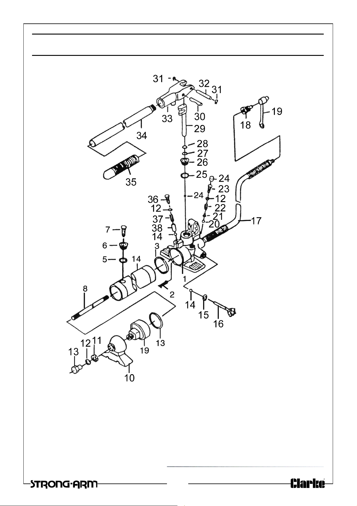
PUMP COMPONENT PARTS
9
Page 10
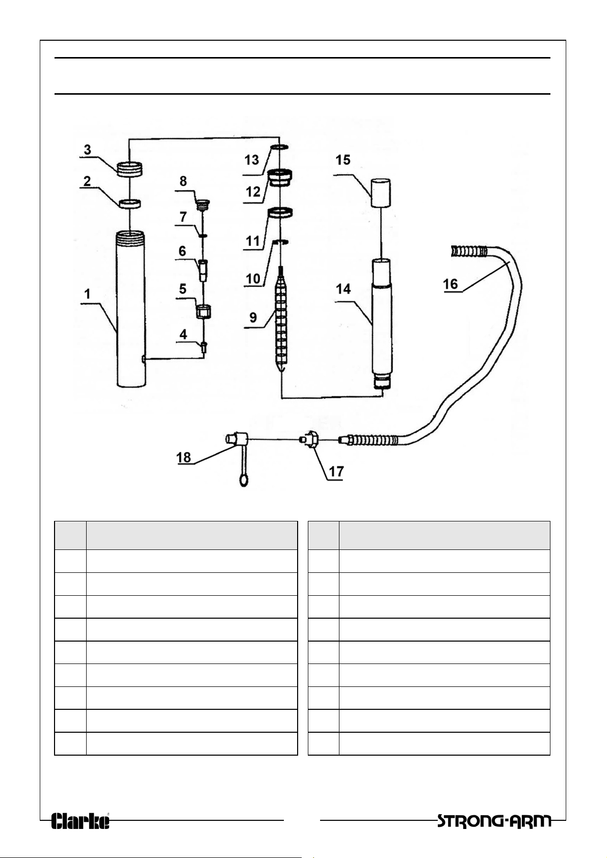
COMPONENT PARTS
No Description No Description
1 Ram Cylinder 10 Circlip
2 Ram Cylinder Seal 11 Nylon Sealing Ring
3 Screw Cover 12 Bushing
4 Screw M6 13 O-ring
5 Connecting Nut 14 Piston Rod
6 Cylinder Screw 15 Piston End Cover
7 O-ring 16 Hydraulic Hose
8 Dust Cover 17 Coupling
9 Tension Spring 18 Dust Seal
10
Page 11
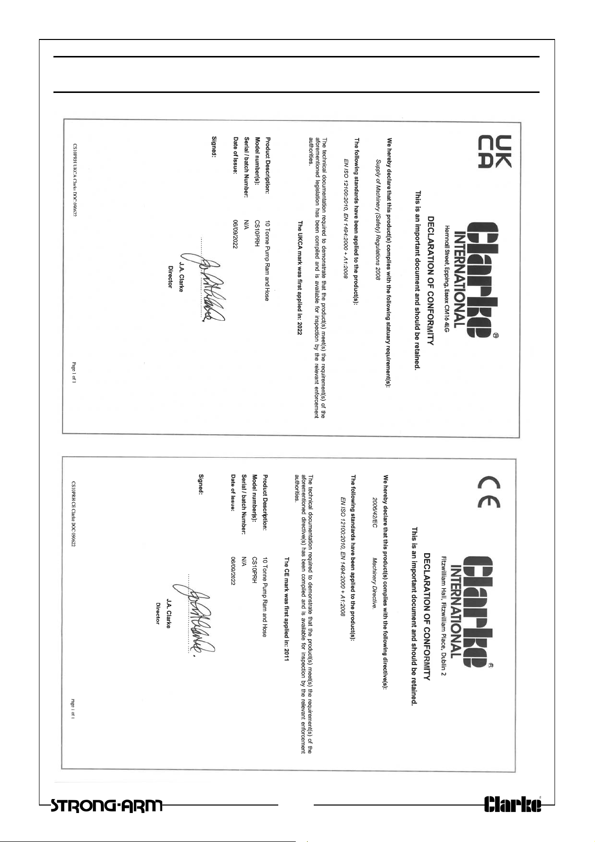
DECLARATION OF CONFORMITY
11
Page 12

 Loading...