

Page 1
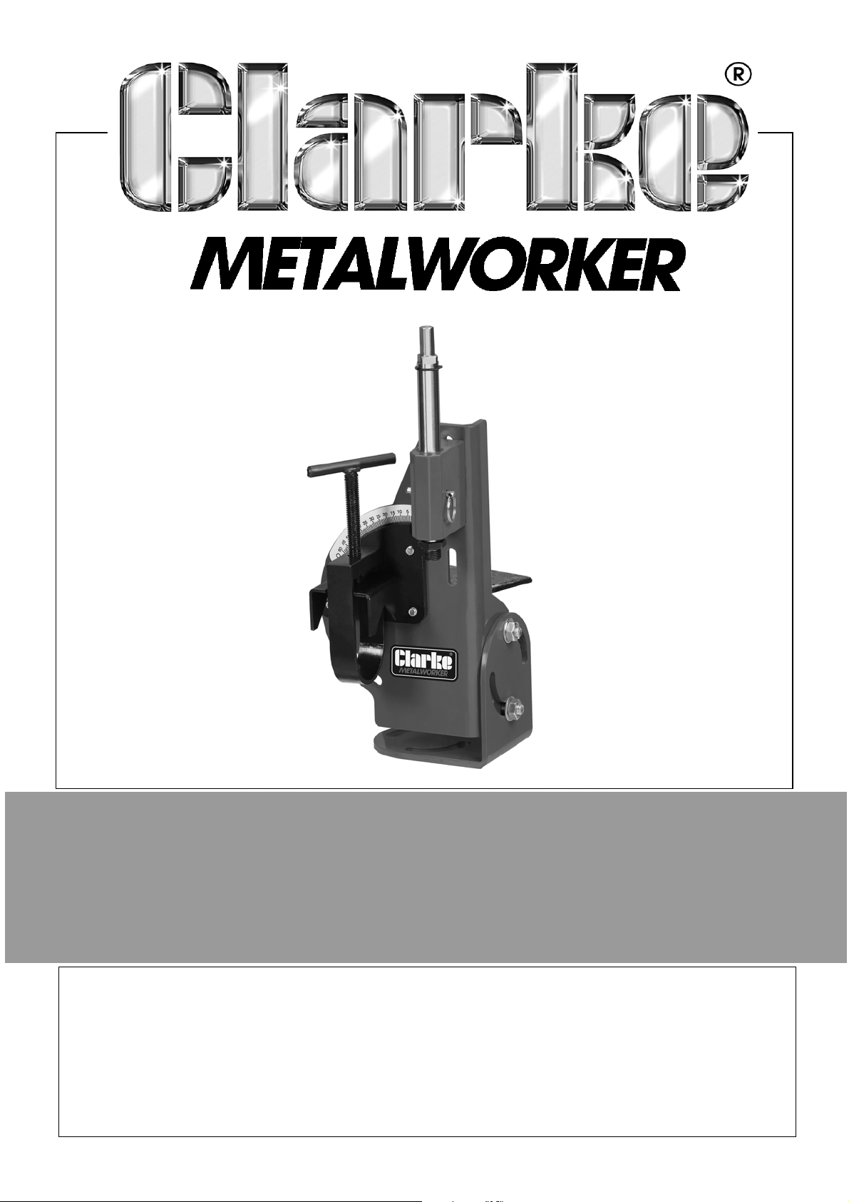
PIPE NOTCHER
MODEL NO: CPTN1
PART NO: 6500101
OPERATION & MAINTENANCE
INSTRUCTIONS
ORIGINAL INSTRUCTIONS DL03/22 - Iss 1
Page 2
INTRODUCTION
Thank you for purchasing this CLARKE Pipe Notcher.
This Pipe Notcher cuts notches in pipe and tubing to make joints that fit
together perfectly. It features a durable steel frame, is cable of 0 - 60
cuts and works with any standard drill press or slow speed hand drill.
Before attempting to use this product, please read this manual thoroughly and
follow the instructions carefully. In doing so you will ensure the safety of yourself
and that of others around you, and you can look forward to your purchase
giving you long and satisfactory service.
o
angle
IMPORTANT
Please read all of the safety and operating instructions carefully before using
this product. Please pay particular attention to all sections of these instructions
that display warning symbols and notices.
WARNING: THIS SYMBOL IS USED THROUGHOUT THE INSTRUCTIONS
WHENEVER THERE IS A HAZARD OR RISK OF PERSONAL INJURY. ENSURE
THAT THESE WARNINGS ARE READ AND UNDERSTOOD AT ALL TIMES.
GUARANTEE
This product is guaranteed against faulty manufacture for a period of 12
months from the date of purchase. Please keep your receipt which will be
required as proof of purchase.
This guarantee is invalid if the product is found to have been abused or
tampered with in any way, or not used for the purpose for which it was
intended.
Faulty goods should be returned to their place of purchase, no product can
be returned to us without prior permission.
This guarantee does not effect your statutory rights.
2
Parts & Service: 020 8988 7400 / E-mail: [email protected] or [email protected]
Page 3
GENERAL SAFETY RULES
WARNING: WHEN USING ELECTRIC TOOLS, BASIC SAFETY
PRECAUTIONS SHOULD ALWAYS BE FOLLOWED TO REDUCE THE RISK
OF FIRE, ELECTRIC SHOCK AND PERSONAL INJURY INCLUDING THE
FOLLOWING. READ ALL THESE INSTRUCTIONS BEFORE ATTEMPTING TO
OPERATE THIS PRODUCT AND SAVE THESE INSTRUCTIONS FOR FUTURE
REFERENCE.
GENERAL SAFETY IN THE WORKPLACE
1. Read this manual carefully. Learn the tools applications and limitations, as
well as the specific potential hazards associated to it.
2. ALWAYS keep work area clean & tidy. Cluttered work areas and benches
invite accidents.
3. ALWAYS use a clamp or make sure the notcher is bolted to a table/
workbench to hold the work. It should NEVER be held with bare hands.
4. NEVER over-reach. Keep proper footing and balance at all times.
5. NEVER store equipment in a wet/damp environment or expose to rain.
6. Keep other persons away. DO NOT let persons, especially children, not
involved in the work, touch the tool and keep them away from the work
area.
7. NEVER operate a machine/tool when under the influence of alcohol, drugs
or medication.
8. ALWAYS ensure the workplace is well lit. Ensure that lighting is placed so that
you will not be working in your own shadow.
9. DO NOT use power tools in the presence of flammable liquids or gasses.
10. Stay alert, watch what you are doing, use common sense and DO NOT
operate the machine/tool when you are tired.
11. ALWAYS remove any adjusting keys or wrenches before starting. Form the
habit of checking to ensure that keys, wrenches and tools are removed
from the machine.
12. DO NOT force the machine and use the correct power tool. It will do the
job better and safer, at the rate for which it was intended.
13. Before further use of the tool, it should be carefully checked to determine
that it will operate properly and perform its intended function. Check for
alignment of moving parts, binding of moving parts, breakage of parts,
mounting or other condition that may affect its operation.
3
Parts & Service: 020 8988 7400 / E-mail: [email protected] or [email protected]
Page 4
14. Have your tool repaired by a qualified person. Repairs should only be
carried out by qualified persons using original spare parts, otherwise this
may result in considerable danger to the user.
15. NEVER use this product for any other purpose than that described in this
manual.
16. ALWAYS refer to the operating and safety instructions provided with your
drill or drill press.
SAFETY SYMBOLS
The following symbols are shown on the product or it’s packaging.
Read instruction
manual before use
Do not wear gloves Wear Ear Protection
Wear a mask
SPECIFICATION
Wear eye protection
(see drill/drill press
manual for relevant
information)
Dimensions (L x W x H) 290mm x 160mm x 410mm
Weight 5 kg
Maximum Tube Diameter 2 inch (50mm)
Chuck Dimension 1/2 inch (12.7mm)
Workpiece Degree Range
Req. Clearance Between Chuck & Table 14 inch (35cm)
Spindle Threads 1/2 & 5/8 Inch (12.7 & 15.9mm)
Parts & Service: 020 8988 7400 / E-mail: [email protected] or [email protected]
0 - 60
4
o
Page 5
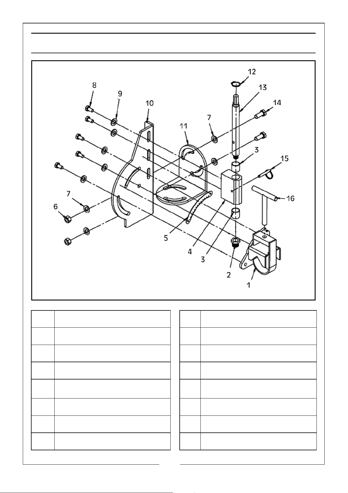
PARTS INVENTORY
1 Clamp Assembly 9 Flat Washer 8mm
2 5/8” Hole Saw Adapter 10 Body
3 Bushing 11 Adjustable Angle Joint Plate
4 Spindle Support 12 External Retaining Ring
5
0 - 60
6 Hex Nut M10 14 Hex Bolt M10
7 Flat Washer 10mm 15 Spindle Lock Pin
8 Hex Bolt M8 16 Clamp T-Handle
Parts & Service: 020 8988 7400 / E-mail: [email protected] or [email protected]
o
Angle Indicator
13 Spindle
5
Page 6
ASSEMBLY
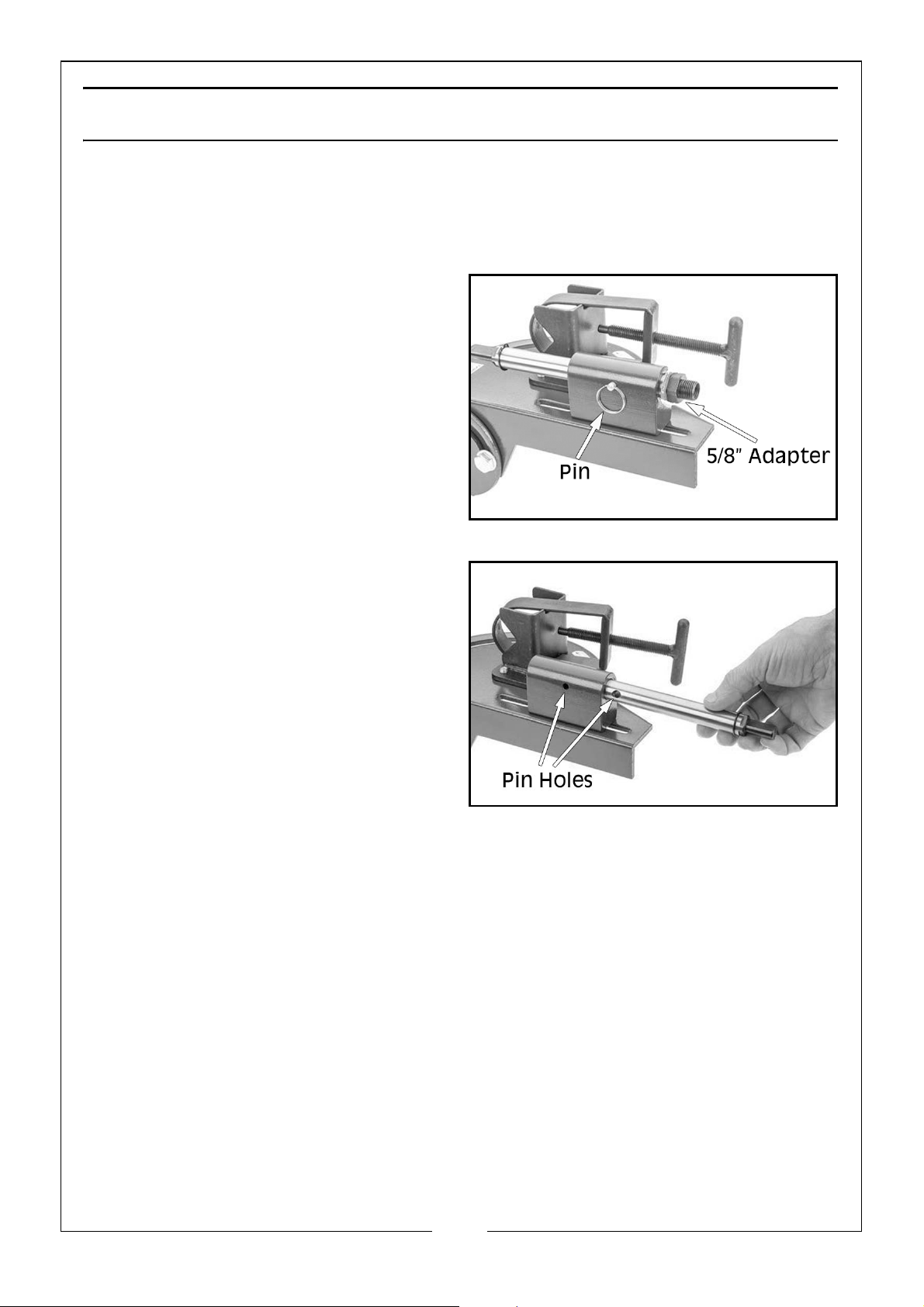
The notcher comes with the spindle inverted. Before use, the spindle must be
removed and turned around.
INSTALL SPINDLE FOR USE
1. Pull the spindle lock pin out to
release the spindle.
2. Remove the 5/8” adapter from
the spindle.
3. Rotate the spindle and re-insert
the spindle, thread end first.
4. Align the hole in the side of the
spindle with the hole in the spindle
support and insert the pin.
INSTALLING THE HOLE SAW AND WORKPIECE
The hole saw attaches to the notcher by threading it onto the end of the
spindle.
ITEMS NEEDED
• 1 x 13mm Open End Spanner or Socket Wrench
• 1 x Hole Saw with 1/2” or 5.8” Thread
6
Parts & Service: 020 8988 7400 / E-mail: [email protected] or [email protected]
Page 7
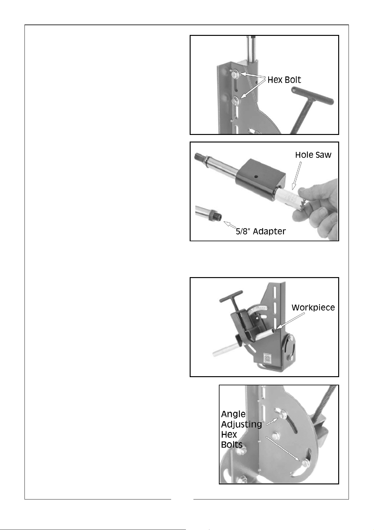
1. Remove the 2 hex bolts, as shown,
from the back of the body and
remove the spindle support from
the notcher.
2. Remove the spindle lock pin.
3. Thread the hole saw on to the
spindle by hand. Thread the 5/8”
adapter onto the spindle before
the hole saw if using a 5/8” hole
saw.
NOTE: For cutting steel pipe and
tubing, it is recommended to
use a bi-metal hole saw.
These can operate at up to 500rpm for most diameters and
should be operated at higher speeds for thin wall tubing.
4. Place workpiece into the clamp
of the notcher as shown, and
tighten the clamp until the
workpiece is secured.
5. Loosen the 2 adjusting angle hex bolts as
shown, adjust the clamp to the desired
angle, then tighten hex bolts.
6. Reattach the spindle support to the
notcher using the hex bolts removed in
step 1.
7
Parts & Service: 020 8988 7400 / E-mail: [email protected] or [email protected]
Page 8
OPERATION
DRILL PRESS OPERATION
To use the notcher with a drill press, the notcher must be clamped securely to
the drill press base. It is important that the notcher is secure enough so it will
not twist or come off of the table during use. To ensure square cuts, the jig must
be square to the base before being mounted to the drill press table.
ITEMS NEEDED
• 1 x 13mm & 2 x 17mm Open End Spanners or Socket Wrenches
• 1 x Hole Saw with 1/2” or 5.8” Thread
• Drill Press with 14” Gap Between Chuck and Table
• Base Fastening Hardware, As Needed
• Cutting Fluid, As Needed
1. Install hole saw and workpiece as described on pages 7 - 8
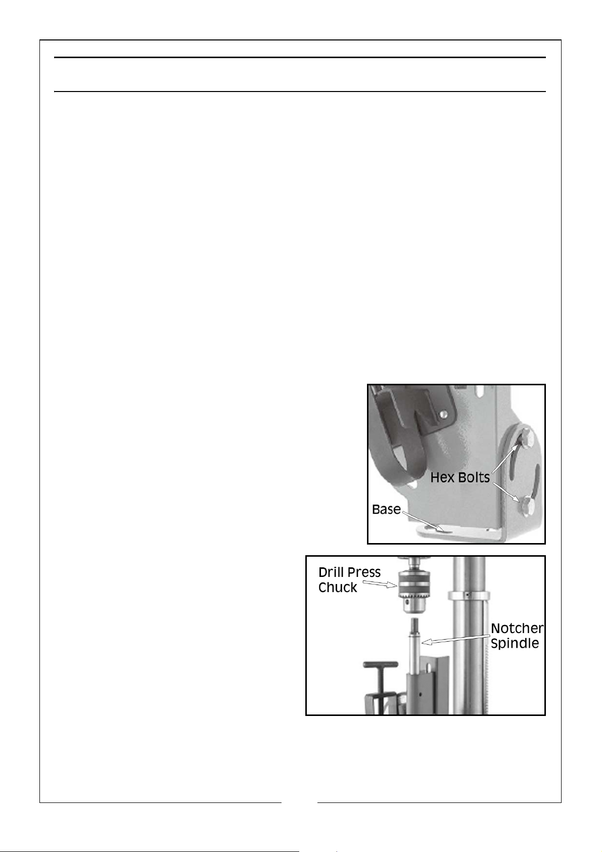
2. Loosen both hex bolts on the angle joint
plate, then swivel the plate until square to
the frame, then tighten the hex bolts.
3. Place the notcher on the drill press
work table and adjust the table
until the top of the notcher spindle
is 1/2” lower than the drill chuck.
4. Loosen the two hex bolts from step 2 just enough so the notcher can be
aligned with the drill chuck.
8
Parts & Service: 020 8988 7400 / E-mail: [email protected] or [email protected]
Page 9
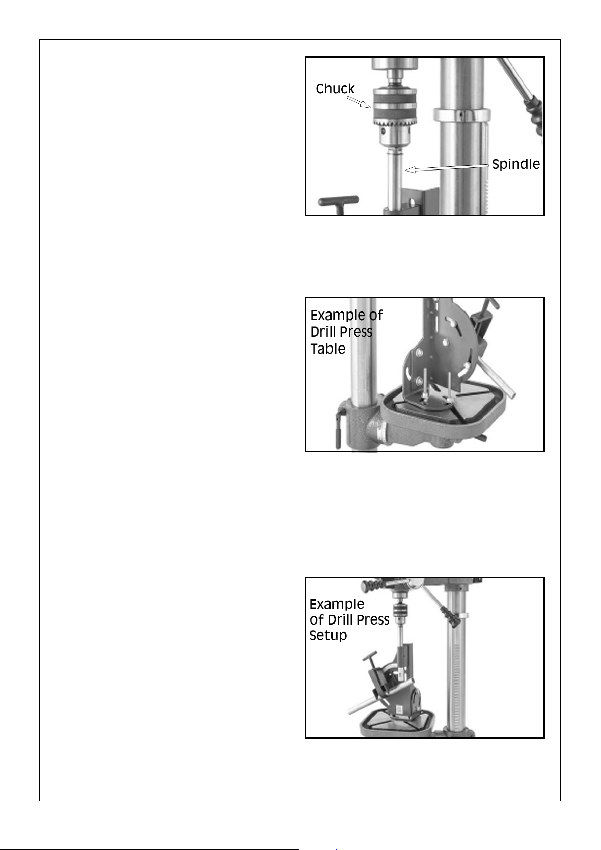
5. Open the drill chuck jaws and
lower the chuck onto the notcher
spindle, aligning the chuck jaws
with the flat sides of the notcher
spindle. Tighten the chuck jaws to
secure.
NOTE: Failure to align the spindle
flats properly with the chuck
jaws may result in the spindle
coming loose and
damaging the notcher and
drill chuck.
6. Adjust the base of the notcher until it is flat to the drill press table, then
tighten the hex bolts from step 2.
7. Secure the base to the table with
bolts, strap clamps or “C” clamps.
8. Remove the spindle lock pin, then
rotate the drill chuck by hand to
test how easily the assembly turns.
NOTE: If assembly turns with minimal
effort, proceed to step 10.
NOTE: If assembly does not turn with
minimal effort, proceed to
step 9.
9. Loosen the 2 hex bolts securing the notcher base to the frame, rotate
spindle then tighten hex bolts, then repeat step 8. repeat until assembly
turns with minimal effort.
10. Loosen bolts/clamps, securing the notcher to the drill press table, rotate
spindle, then tighten the bolts/clamps. Spindle should turn freely.
11. When the notcher is correctly
installed on the drill press, remove
the spindle lock pin, apply cutting
fluid, turn drill press on and
perform notching operation.
9
Parts & Service: 020 8988 7400 / E-mail: [email protected] or [email protected]
Page 10
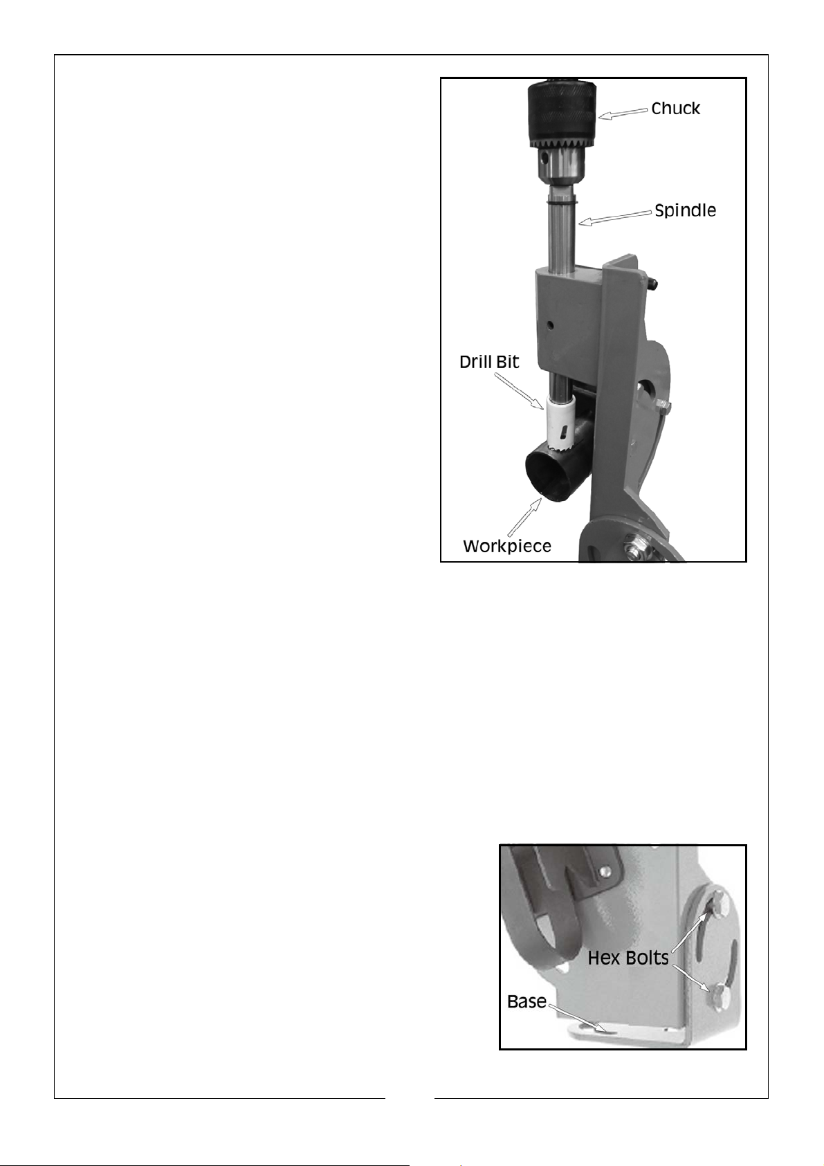
12. With the lock pin removed, apply
cutting fluid, turn drill press On and
perform the notching procedure.
HAND DRILL OPERATION
ITEMS NEEDED
• 1 x 13mm & 2 x 17mm Open End Spanners or Socket Wrenches
• 1 x Hole Saw with 1/2” or 5/8” Thread
• Workbench Mounting Hardware (Not Supplied), As Needed
• Hand Drill
• Cutting Fluid, As Needed
1. Install hole saw and workpiece as described on pages 7 - 8.
2. Mount notcher to workbench using
mounting hardware (not included).
3. Loosen both hex bolts, as shown, swivel
base to desired drilling angle, and tighten
hex bolts.
10
Parts & Service: 020 8988 7400 / E-mail: [email protected] or [email protected]
Page 11
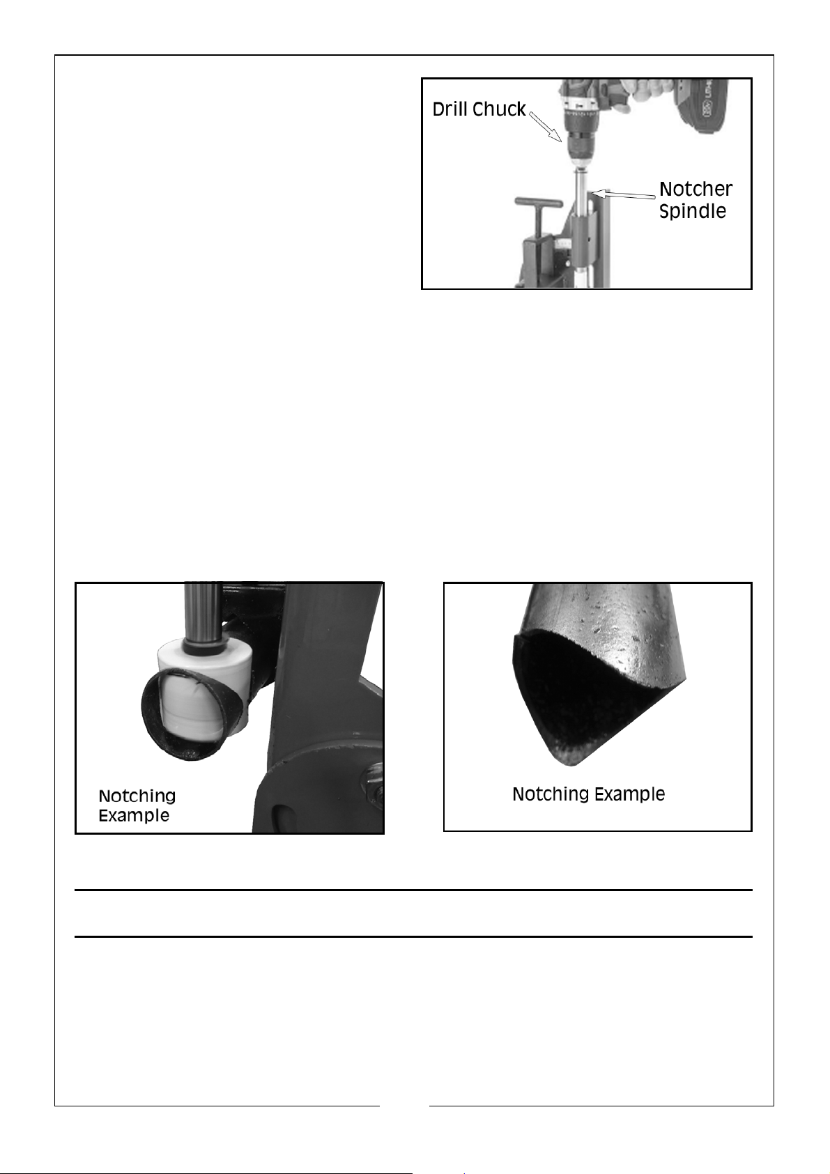
4. Open drill chuck jaws and place
chuck onto the notcher spindle,
making sure the chuck jaws align
with the flat sides of the notcher
spindle, then tighten the chuck
jaws to secure.
5. Remove spindle lock pin from the spindle and rotate the drill chuck by
hand to test how easily the whole assembly turns.
NOTE: If assembly turns with minimal effort, proceed to step 6.
NOTE: If assembly does not turn with minimal effort, adjust the angle of
the drill until it does, then proceed to step 6.
NOTE: Failure to align the spindle flats properly with the chuck jaws may
result in the spindle coming loose and damaging the notcher and
drill chuck.
6. With the lock pin removed, apply cutting fluid, turn drill On and perform the
notching procedure.
ACCESSORIES
• Clarke CHT576 - 6pc Plumbers Hole Saw Set, Part No: 1801576
• Clarke CHT575 - 6pc Electricians Hole Saw Set, Part No: 1801575
• Clarke CDP5EB - Drill Press, Part No: 6550030
11
Parts & Service: 020 8988 7400 / E-mail: [email protected] or [email protected]
Page 12

 Loading...