

Page 1
1
0706
Part No. 6460200
MODEL Nos. CPT600 and CPT800
Part No. 6462130 and 6462135
OPERATING & MAINTENANCE
INSTRUCTIONS
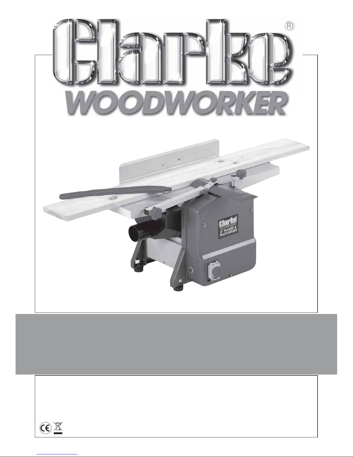
PLANER/THICKNESSER
PLANER/THICKNESSER
Page 2

2
SPECIFICATIONS
Model ................................................................. CPT600........................ CPT800
Part No ................................................................. 6462130 ....................... 6462135
Voltage ................................................................ 230VAC ...................... 23 0VA C
Power Input ......................................................... 1250Watts ................... 1250Watts
Plug Fuse Rating ................................................. 13Amps ....................... 13Amps
Input Wattage Max............................................ 3.7Amps ...................... 3.7Amps
Cutter Speed ...................................................... 8700 rpm ..................... 8700 rpm
Weight - unpacked ............................................ 22 Kg ........................... 24.5kg
Sound Power Level - Measured........................ 103.4dBL
WA .............................
99.7dBL
WA
Max Cutting Depth ............................................ 2mm ............................ 2mm
Max Timber Width............................................... 152mm ........................ 204mm
Min Timber size - Thicknesser ............................. 5-120mm ..................... 5-120mm
Fence Angular Movement................................ 90O - 135
O
...................................
90O - 135
O
Table Dimensions ................................................ 660x160mm ................ 737x210mm
Exhaust Port Dia. ................................................. 50mm .......................... 63mm
Dimensions LxWxH .............................................. 693x437x357mm ........ 770x449x405mm
LIST OF PACKAGE CONTENTS
1 x Planer/Thicknesser
1 x Side Fence
1 x 5mm Allen Key
1 x Thicknessing Table Raise/Lower Handle
1 x Push Stick
1 x Dust Extraction Chute
2 x Spare Drive Belts
1 x Instruction Manual
Please note that the details and specifications contained herein are correct at the time of going to
print. However CLARKE International reserve the right to change specifications at any time without
prior notice. Always consult the machines data bracket
© Copyright CLARKE International. All rights reserved. April 2006
When disposing of this equipment, it must be disposed of according to all local ordinances. DO NOT dispose of
with normal houshold waste.
Page 3
3
Please read these instructions carefully before operating the tool
Thank you for purchasing this CLARKE Planer/Thicknesser designed for DIY use.
Before using the device, please read this manual thoroughly and carefully follow all
instructions given. This is for your own safety and that of others around you, and is also to
help you achieve a long and trouble free service from your new tool.
CLARKE GUARANTEE
This CLARKE product is guaranteed against faulty manufacture for a period
of 12 months from the date of purchase. Please keep your receipt as proof
of purchase.
This guarantee is invalid if the product is found to have been abused or
tampered with in any way, or not used for the purpose for which it was
intended.
Faulty goods should be returned to their place of purchase, no product
can be returned to us without prior permission.
This guarantee does not affect your statutory rights.
CONTENTS Page
Specifications : .............................................................................................. 1
Guarantee : ................................................................................................... 3
General Safety Precautions : ...................................................................... 4
Additional Precautions for Planer/Thicknessers ........................................ 5
Electrical Connections : ............................................................................... 6
Assembly : ...................................................................................................... 7
Operation : .................................................................................................... 9
Maintenance :............................................................................................. 11
Parts Diagrams and Lists :...................................................................... 15-22
Parts and Service Contacts : ..................................................................... 23
Declaration of Conformity :....................................................................... 23
Page 4
4
General Safety Precautions
WARNING:
As with all machinery, there are certain hazards involved with their operation
and use. Exercising respect and caution will considerably lessen the risk of
personal injury. However, if normal safety precautions are overlooked or
ignored, personal injury to the operator or damage to property, may result.
1. ALWAYS Learn the machines’ applications, limitations and the specific potential
hazards peculiar to it. Read and become familiar with the entire
operating manual.
2. ALWAYS use a face or dust mask if operation is particularly dusty.
3. ALWAYS check for damage. Before using the machine, any
damaged part, should be checked to ensure that it will operate
properly, and perfor m its intended function. Check for alignment of
moving parts, breakage of parts, mountings, and any other condition
that may affect the machines’ operation. Any damage should be properly repaired
or the part replaced. If in doubt, DO NOT use the machine. Consult your local dealer.
4. ALWAYS disconnect the tool/machine from the power supply before servicing and
when changing accessories.
5. ALWAYS wear safety goggles, manufactured to the latest European Safety Standards.
Everyday eyeglasses do not have impact resistant lenses, they are not safety glasses.
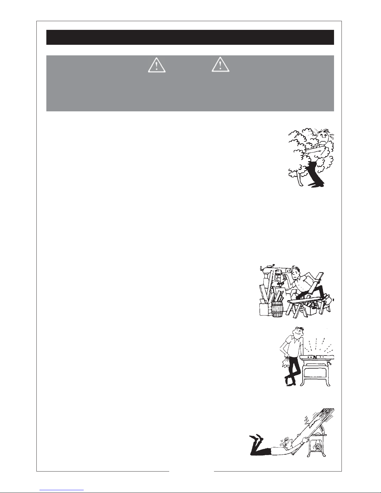
6. ALWAYS keep work area clean. Cluttered areas and benches
invite accidents.
7. ALWAYS ensure that adequate lighting is available. A
minimum intensity of 300 lux should be provided. Ensure
that lighting is placed so that you will not be working in your
own shadow.
8. ALWAYS keep children away. All visitors should be kept a
safe distance from the work area, especially whilst operating the machine.
9. ALWAYS maintain machine in top condition. Keep tools/machines
clean for the best and safest perfor mance. Follow maintenance
instructions.
10. ALWAYS handle with extreme care do not carry the tool/machine
by its’ electric cable, or yank the cable to disconnect it from the
power supply .
11. ALWAYS ensure the switch is off before plugging in to mains. Avoid accidental starting.
12. ALWAYS concentrate on the job in hand, no matter how trivial it may seem. Be aware
that accidents are caused by carelessness due to
familiarity.
13. ALWAYS keep your proper footing and balance at all
times, don’t overreach. For best footing, wear rubber
soled footwear. Keep floor clear of oil, scrap wood, etc.
Page 5

5
14. ALWAYS wear proper apparel. Loose clothing or jewellery may
get caught in moving parts. Wear protective hair covering
to contain long hair.
15. ALWAYS use recommended accessories, the use of improper
accessories could be hazardous.
16. ALWAYS remove plug from electrical outlet when adjusting,
changing parts, or working on the machine.
17. NEVER operate machine while under the influence of drugs, alcohol or any medication.
18. NEVER leave machine running unattended. tur n power off.
Do not leave the machine until it comes to a complete stop.
19. NEVER force the machine, it will do a better and safer job at
the rate for which it was designed.
20. NEVER use power tools in damp or wet locations or expose
them to rain. Keep your work area well illuminated.
21. DO NOT use in explosive atmosphere (around paint,
flammable liquids etc). Avoid dangerous environment.
ADDITIONAL PRECAUTIONS FOR PLANER/THICKNESSERS
1. ALWA YS ensure the cutters are properly secured in the cutter block before use.
2. ALWA YS ensure the cutters are sharp, blunt cutters increase the risk of kick back.
3. ALWA YS switch the machine OFF immediately the task is completed.
4. ALWA YS ensure safety devices etc., are in place and working correctly, if not DO NOT
use the machine until they are.
5. ALWA YS use with a dust extraction device fitted.
6. ALWA YS allow the machine to reach full speed before introducing workpiece.
7. DO NOT use the machine if the electric cable, plug or motor is in poor condition.
8. DO NOT allow the ventilation slots in the machine to become blocked.
9. DO NOT touch the cutter immediately after use, allow time for it to cool.
10. NEVER leave machine running unattended, ALWAYS ensure the machine is switched
off and come to a complete stop before leaving it.
11. NEVER use the machine with any of the guards removed.
12. NEVER attempt to reverse the workpiece towards the infeed.
13. NEVER proceed unless the workpiece has been thoroughly checked to ensure it is
completely free of nails, screws, staples etc.
14. NEVER plane a piece of wood without the Cutter Guard completely covering any
exposed Cutter Blade
15. AVOID accidental starting, by switching off and isolating from the main electrical
supply by removing the plug from the socket.
16. REGULARLY check to ensure the ‘Anti-Kickback pawls operate correctly.
17. IMPORTANT! This machine develops considerable noise when in use. ALWAYS wear Ear
Defenders
Additionally, please keep these instructions in a safe place for future reference.
Page 6
6
ELECTRICAL CONNECTIONS
Connect the mains lead to a domestic, 230 volt (50Hz) electrical supply through a fused
good quality 13 amp BS 1363 plug, or a suitable fused isolator switch.
WARNING: THIS APPLIANCE MUST BE EARTHED
IMPORT ANT: The wir es in the mains lead are colour ed in accordance with the following code:
Green & Yellow - Earth
Blue - Neutral
Brown - Live
As the colours of the conductor insulation of this appliance may not correspond with the coloured
markings identifying terminals in your plug, you should proceed to connect as follows:
• The GREEN & YELLOW conductor to the terminal marked with a letter “E” or Earth
symbol ‘ ’ or coloured GREEN or GREEN & YELLOW.
• The BROWN conductor to the terminal marked “L” or coloured RED.
• The BLUE conductor to the terminal marked “N” or coloured BLACK.
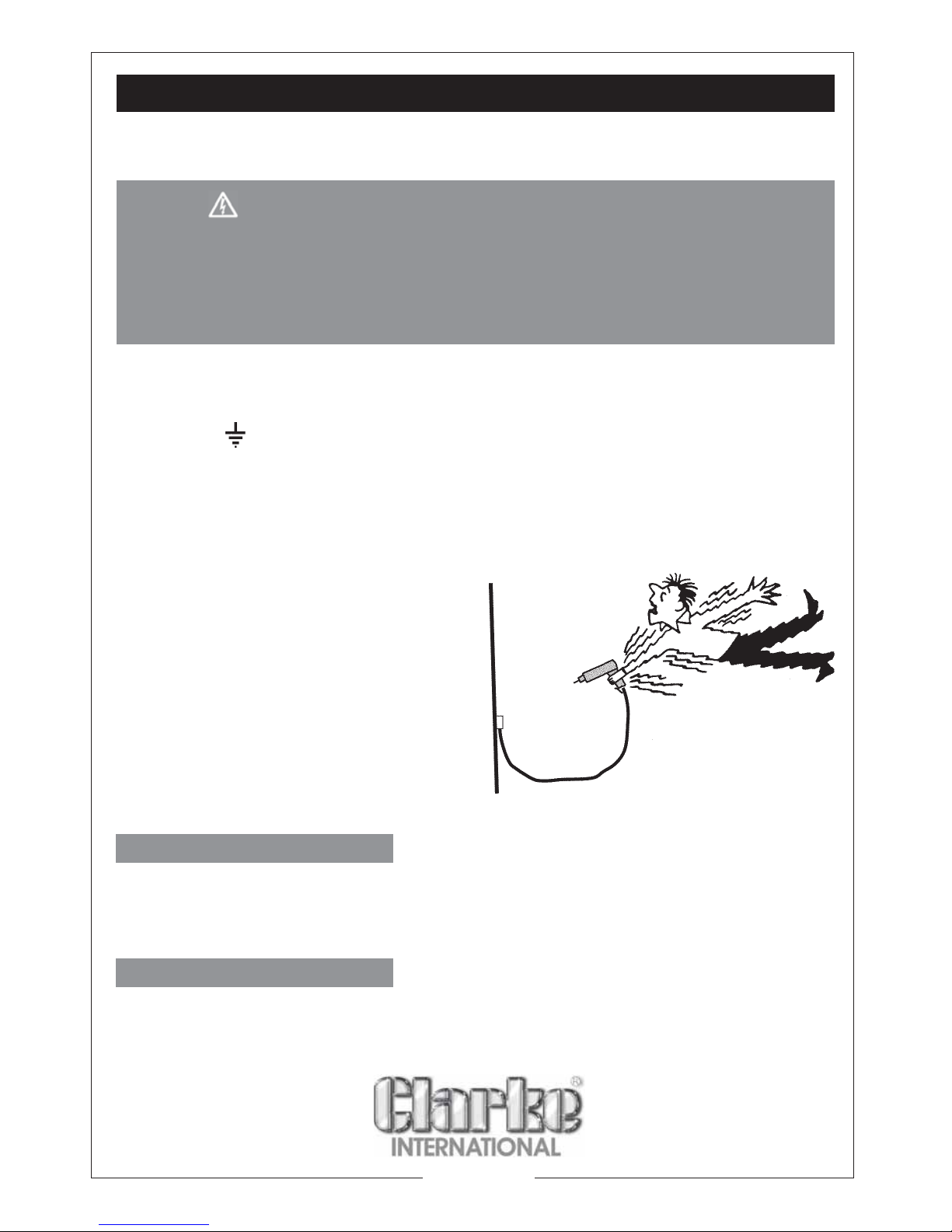
If this appliance is fitted with a plug which is moulded on to the electric cable (i.e. nonrewireable) please note:
1. The plug must be thrown away if it is cut
from the electric cable. There is a
danger of electric shock if it is
subsequently inserted into a socket
outlet.
2. Never use the plug without the fuse
cover fitted.
3. Should you wish to replace a
detachable fuse carrier, ensure that
the correct replacement is
used (as indicated by marking or colour
code).
FUSE RATING
The fuse in the plug must be replaced with one of the same rating (13 amps) and this
replacement must be ASTA approved to BS1362.
If in doubt, consult a qualified electrician. Do not attempt any electrical repairs yourself.
CABLE EXTENSION
Always use an approved cable extension suitable for the power rating of this tool (see
specifications), the conductor size should also be at least the same size as that on the
machine, or larger. When using a cable reel, always unwind the cable completely.
Page 7

7
UNPACKING and PARTS IDENTIFICATION
ASSEMBLY and INSTALLATION
Fig. 1
Carefully unpack the components and lay them out, checking against the
following list. Should any part be missing or damaged in transit, please contact
your Clarke dealer immediately.
Ensure the planer is located where there is adequate light, and a suitable power
supply. If cable a extension is used, ensure it does not trail along the workshop
floor as this could be extremely hazardous.
There must be sufficient room for the workpiece to move through its entire length.
Similarly, there must be sufficient room so that the operator does NOT need to
stand in line with the wood during the planing process.
The planer may be used as a mobile unit, but for greater stability we recommend
it is bolted to a strong, firm workbench. The dimensions for the mounting holes are
shown below:
Alternatively, mount the planer on a
strong piece of plywood of at least
15mm in thickness, with length
550mm and width 380mm minimum.
The plywood platform, with planer
mounted, is then clamped firmly to a
workbench when required.
Fig. 2
NOTE:
Dust extraction
devices are
available from
your Clarke dealer
Page 8
8
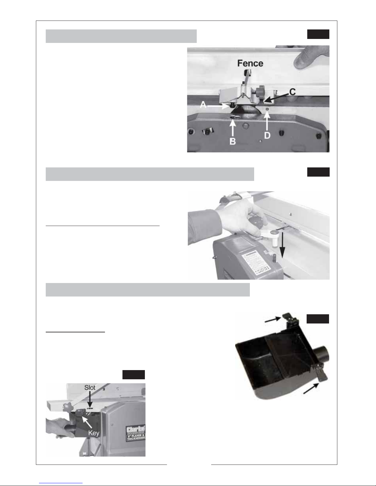
1. Attaching the Angle Fence
The peg - ‘A’ locates in the slotted
hole - ‘B’. It may be necessary to screw
the peg down a little in order for the
peg to locate properly.
The Hex. socket head screw with
washers (in the bag of loose parts), is
used to secure the fence to the table,
through slot ‘C’, into threaded hole ‘D’.
The fence may be set and locked at
any angle. Use a template or angle
gauge if accuracy is required.
3. Attach the Dust/Chip Extraction Chute
A. For Planing
A.1 Lower the Thicknesser Table as far as
possible by turning the table adjustment
handle (see Fig.4) fully anticlockwise.
Fig. 3
Fig. 5
A.2 Pull out the two Locking Keys (arrowed in
Fig.5) and manoeuvre the Chute into the
space beneath the table.
Ensure both Locking keys are pushed firmly
into the slots in the table, shown in Fig.6.
Fig. 6
IMPORTANT: Please note that the Dust Chute MUST ALW AYS be in place, the machine
will not operate if is removed.
2. Attaching the Table Adjustment Handle
Slide the table adjustment handle (16)
onto the shaft (see Fig. 4).
To raise or lower the table.
Adjust the thicknesser table by turning
the table adjustment handle:
Lower the table - Turn anticlockwise.
Raise the table - Turn clockwise.
Fig. 4
Page 9
9
B. For Thicknessing
B.1 Remove the Angle Fence.
B.2 Push the Cutter Guard out of its
holder so that the Chute may be
attached to the table, as shown
in Fig.7.
Ensure both Locking keys are pushed
firmly into the slots in the table, shown
in Fig.6.
Fig. 7
1. Set the depth of cut, using the Depth of Cut Setting Knob - see Fig.1. Turn
anticlockwise to increase the cutting depth, clockwise to decrease, using the
scale, indicated in Fig. 8, as a reference. For the initial cut, we recommend a
depth of cut of no more than 1mm. The maximum depth of cut is 2mm.
2. Ensure the fence is at the correct angle - for normal planing, this would be 90
degrees. For other angles, use a template or angle gauge for greater accuracy.
OPERATION
A. Planing
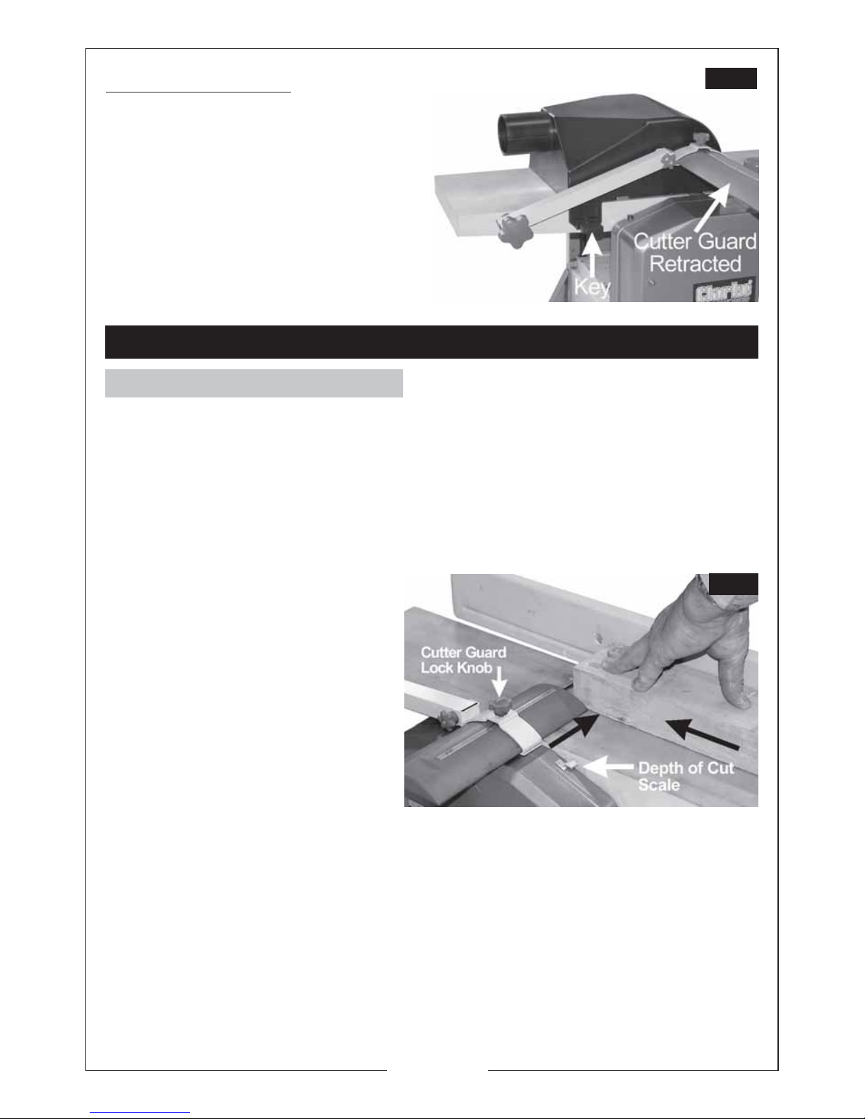
3. Slide the cutter guard out of the
way and place the workpiece on
the table so that it rests snugly
against the fence, with the lead
edge a short distance from the
cutter, noting that direction of
feed is right to left, looking from
the front of the machine.
4. Slide the cutter guard up to lightly
touch the workpiece as shown
in Fig.8, thereby completely
covering any exposed cutter .
Fig. 8
Ensure the guard is as low as possible and the Cutter Guard Lock Knob is tightened.
5. Raise the cover of the ON/OFF switch and press the green ON button, marked
‘I’, and allow the machine to come up to full speed.
6. Applying firm downwards pressur e, and keeping the workpiece against the
fence, proceed to feed the work over the cutter. Do not feed too quickly
ENSURE the timber is completely free of nails, screws and staples etc., before use.
ALWAYS use Supports for long
pieces - Roller Stands etc.
Page 10
10
B. Thicknessing
1. Lower the Thicknessing table sufficiently for the workpiece to be inserted
beneath the cutter blade, ensuring the blade is at 6 o’clock. Work enters
from the left and exits at the right of the machine,
2. Raise the table until there is slight resistance. i.e. the work just touches the blade.
3. Withdraw the workpiece, then wind the table upwards - turn clockwise, using
the Raise/Lower Table knob, to the appropriate cutting depth, noting that
one turn is equivalent to 3mm. Do not exceed 2mm depth of cut as this could
cause kickback, and/or damage to the components or overheating of the
motor.
Note: It is advisable when working with rough or warped wood to make very small
depths of cut to begin with - 1mm should be sufficient.
4. Support the workpiece at the desired height, so that it is horizontal and feed it
into the cutter, from the left hand side of the machine. The rollers will
automatically feed the work past the kick-back pawls and into the cutter
blade. Ensure it is well supported at the outlet side
DO NOT remove chips or shavings from the table until the machine has stopped
completely and is isolated from the mains supply.
NOTE:
1. The workpiece should always be 2-3 inches longer than the finished length as
the ends tend to be uneven.
2. The table should be lubricated with wax, frequently to ensure smooth operation.
IMPORT ANT.
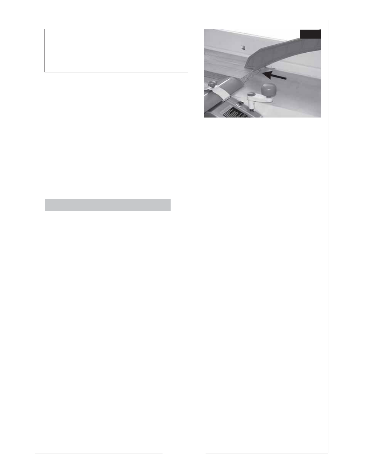
When coming to the end of a piece,
ALWAYS use the push stick to finish - see
Fig.8. This is an important safety point.
surrounding area and dispose of safely, accumulation of dust and shavings is a
fire hazard and should not be allowed to build up.
NOTES :
1. In case of emergency, hit the switch cover firmly and quickly. The cover will
latch down and motor will be switched OFF.
2. The ON/OFF switch is a “No Volt Release” type , so that in the event of a power
failure, the machine will not restart automatically once the power is restored.
7. To switch OFF, simply press the red
button marked ‘O’ and close the
cover ensuring it is properly latched.
When finished, remove all shavings and
sawdust from the machine and
Fig. 9
Page 11

11
C. Reset Button
The table saw is fitted with an thermal
overload protector. If the motor stops
running or fails to start.
1. Close the safety switch cover and allow
the motor to cool for five minutes.
2. Press the reset button.
3. Raise the cover of the ON/OFF switch
and press the green ON button, marked
‘I’.
Always disconnect the machine from the mains supply before cleaning or
performing maintenance tasks.
This product is designed to operate with minimum of maintenance, however, as
with all power tools, cleanliness is essential in ensuring work is carried out to a
satisfactory standard. Always keep the table free of shavings/dust etc., and clean
the machine thoroughly after use. Use a low pressure air supply to blow dust from
air vents and other parts wherever possible.
Apply a thin film of wax to the table periodically. This will help keep the table
clean and allow the workpiece to slide more easily.
Do not use solvents to clean the machine as this could damage plastic
components.
Cutter Blade Removal
Cutter blades will require sharpening or replacing. Care should be taken at all
times when handling them, they are very sharp, even when appearing to be dull.
Blades must always be fitted as a pair, and must be of the same type, only fit blades
recommended by the Clarke International.
First, ensure the machine is switched OFF and isolated from the mains supply.
1. Turn the cutter height adjuster so that it registers zero. i.e. turn the knob
clockwise so that the depth of cut, registered on the scale, is zero.
1. Remove the Angle Fence.
2. Raise the Cutter Guard arm.
3. Turn the cutter block to reveal the four hex. socket head screws securing the
cutter blade, then carefully remove them.
4. Turn the cutter block by 180 degrees and repeat the process.
ALWAYS hone/replace cutter blades as a pair.
MAINTENANCE
Page 12
12
Fig. 10
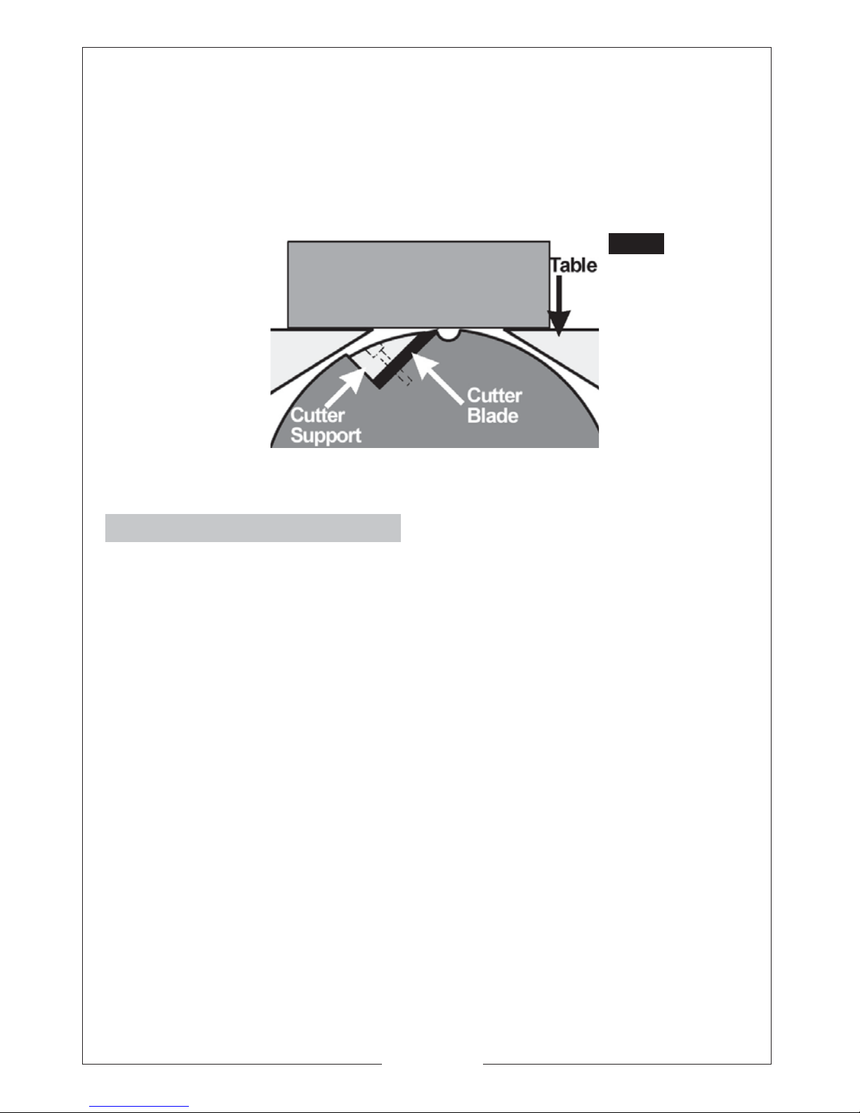
5. Replace in reverse order, and, using a straight edge, ensure the cutting edges
are level and in line with the table when they are at 12 o’clock - see
Fig.10. Tighten the securing screws taking care not to over-tighten or damage
the hex. sockets..
NOTE: It is recommended that sharpening is done professionally, using a jig, as
blades must be sharpened as a pair to ensure they are correctly balanced. This
avoids the possibility of vibration due to inbalanced cutters rotating at speed.
Fig. 10
Periodically.
• Wipe both the infeed and outfeed rollers with a damp cloth to remove all
traces of contaminants.
• Wax the Thicknesser table frequently to ensure a smooth and reliable feed.
• Inspect the kickback pawls before each operation to ensure they are intact
and working properly. They should hang normally and loosely.
• Remove the front cover - 3 dome head nuts, and lightly oil all pivots, linkages
and bearings with good quality machine oil. Ensure the enclosure and all
components are perfectly clean before replacing the cover.
Page 13

13
Drive Belt Replacement.
1. Remove the front cover - 3 nuts.
2. Remove the worn or broken drive
belt.
Fig. 11
Fig. 12
3. Place the replacement drive belt
over the small belt wheel.
4. Position part of the drive belt over
the large belt wheel as shown in fig
12.
5. Rotate the large belt wheel by
hand in a clockwise direction whilst
guiding the belt on to the belt
wheel. See fig 13.
Fig. 13
Page 14

14
Page 15

15
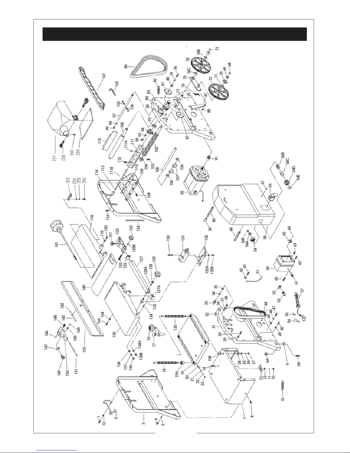
CPT600
Exploded Diagram &
Parts List
Page 16
16
SPARE PARTS DIAGRAM - CPT600
Page 17
17
PARTS LIST
No. Description Qty Part No. No. Description Qty Part No.
42 Cable Clamp NXCPT6042
43 Rubber Buffer NXCPT6043
44 Flat Belt NXCPT6044
45 Washer NXCPT6045
46 Locking Washer NXCPT6046
47 Bolt NXCPT6047
48 Rod,Long NXCPT6048
49 Washer NXCPT6049
50 Bolt NXCPT6050
52 Plastic Locknut NXCPT6052
53 Strain Relief NXCPT6053
54 Nut NXCPT6054
54A Washer NXCPT6054A
54B Spring NXCPT6054B
54C Rod NXCPT6054C
54D Screw NXCPT6054D
54E Scale NXCPT6054E
54F Screw NXCPT6054F
55 Locking Line NXCPT6055
56 Rubber Set NXCPT6056
57 Power Cable NXCPT6057
58 Protecting Hood NXCPT6058
59 Switch Box NXCPT6059
60 Bolt NXCPT6060
61 Thermo-protector NXCPT6061
62 Bolt NXCPT6062
63 Bolt NXCPT6063
64 Bolt NXCPT6064
65 Terminal NXCPT6065
66 Switch NXCPT6066
67 Nut NXCPT6067
68 Locking Ring NXCPT6068
69 Washer NXCPT6069
70 Chain Wheel NXCPT6070
71 Square Sleeve NXCPT6071
72 Gear Wheel NXCPT6072
73 Locking Ring NXCPT6073
74 Large Belt Wheel NXCPT6074
74B Lanter n Ring NXCPT6074B
74C Needle Bearing NXCPT6074C
75 Pivot Plate NXCPT6075
76 Retracting Spring NXCPT6076
77 Arbor NXCPT6077
1 Bolt NXCPT6001
2 Cord Stowage Bkt NXCPT6002
3 Side Cover NXCPT6003
4 Bolt NXCPT6004
5 Locking Washer NXCPT6005
6 Rubber Foot NXCPT6006
6A Nut NXCPT6006A
7 Motor Cover NXCPT6007
8 Bolt NXCPT6008
10 Nut NXCPT6010
11 Locking Washer NXCPT6011
12 Washer NXCPT6012
13 Angle Plate NXCPT6013
14 Bolt NXCPT6014
15 Chain NXCPT6015
16 Adjustment Handle NXCPT6016
17 Plug NXCPT6017
18 Threaded Spindle,Short NXCPT6018
19 Table NXCPT6019
19A Threaded Spindle Nut NXCPT6019A
19B Sleeve NXCPT6019B
20 Pointer NXCPT6020
21 Locking Washer NXCPT6021
22 Washer NXCPT6022
23 Bolt NXCPT6023
24 Chain Wheel NXCPT6024
25 Washer NXCPT6025
26 Locking Washer NXCPT6026
27 Hexagonal Nut NXCPT6027
28 Bolt NXCPT6028
29 Sleeve NXCPT6029
30 Bolt NXCPT6030
31 Side Plate ,Left NXCPT6031
32 Cutting Depth Scale NXCPT6032
33 Bolt NXCPT6033
34 Locking Washer NXCPT6034
35 Washer NXCPT6035
36 Washer NXCPT6036
37 Locking Washer NXCPT6037
38 Hexagonal Nut NXCPT6038
39 Bolt NXCPT6039
40 Rod,Long NXCPT6040
41 Bolt NXCPT6041
Page 18

18
No. Description Qty Part No. No. Description Qty Part No.
78 Bolt NXCPT6078
79 Locking Washer NXCPT6079
80 Washer NXCPT6080
81 Chain Wheel NXCPT608/1
82 Chain NXCPT6082
83 Small Belt Wheel NXCPT6083
84 Bolt NXCPT6084
85 Bolt NXCPT6085
86 Flat Belt NXCPT6086
87 Supporting Plate NXCPT6087
88 Post NXCPT6088
91 Motor Belt Wheel NXCPT6091
92 Motor NXCPT6092
93 Grooved Ball Bearing NXCPT6093
94 Bearing Cover NXCPT6094
95 Locking Washer NXCPT6095
96 Hexagonal Nut NXCPT6096
97 Strut NXCPT6097
98 Washer NXCPT6098
99 Bolt NXCPT6099
100 Feed-out Roller NXCPT6100
102 Feed-in Roller NXCPT6102
103 Retracting Spring NXCPT6103
104 Bearing Bush NXCPT6104
105 Rod NXCPT6105
106 Washer NXCPT6106
107 Ratchet NXCPT6107
108 Bolt NXCPT6108
109 Clamping Device NXCPT6109
110 Cutter Blade NXCPT6110
111 Cutter Block NXCPT6111
111A Bolt NXCPT6111A
111B Arbor NXCPT6111B
112 Bolt NXCPT6112
113 Needle Bearing NXCPT6113
114 Bearing Cap NXCPT6114
115 Sheet Metal Deflector NXCPT6115
116 Retracting Spring NXCPT6116
118 Front Table Top NXCPT6118
119 Sliding Block NXCPT6119
120 Bolt NXCPT6120
121 Hand Knob NXCPT6121
122 Cutter Guar d Holder NXCPT6122
123 Hand Knob NXCPT6123
124 Scale NXCPT6124
125 Stud Bolt NXCPT6125
126 Cover NXCPT6126
127 Square Tube NXCPT6127
127A Cover NXCPT6127A
128 Washer NXCPT6128
128A Locking Ring NXCPT6128A
128B Locking Ring NXCPT6128B
129 Hand Knob NXCPT6129
130 Bolt NXCPT6130
131 Limit Switch NXCPT6131
132 Switch Cover NXCPT6132
132A Washer NXCPT6132A
132B Bolt NXCPT6132B
133 Stud Bolt NXCPT6133
134 Stop Screw NXCPT6134
134A Locking Washer NXCPT6134A
134B Nut NXCPT6134B
135 Threaded Spindle,Long NXCPT6135
136 Hexagonal Nut NXCPT6136
137 Locking Washer NXCPT6137
138 Washer NXCPT6138
139 Rear Table Top NXCPT6139
140 Cutter Guard NXCPT6140
141 Spindle NXCPT6141
142 Stalk,Short NXCPT6142
143 Angle Fence Plate NXCPT6143
145 N ut NXCPT6145
146 Bolt NXCPT6146
147 N ut NXCPT6147
148 Bolt NXCPT6148
149 Hand Knob NXCPT6149
150 Angle Piece NXCPT6150
151 Stalk,Long NXCPT6151
152 Guide Fence NXCPT6152
153 Clamp Plate NXCPT6153
154 Washer NXCPT6154
155 Locking Washer NXCPT6155
156 Bolt NXCPT6156
157 Dust Collector NXCPT6157
158 Key Assembly NXCPT6158
159 Cover NXCPT6159
160 Bolt NXCPT6160
161 Push Stick NXCPT6161
162 Hex Wrench NXCPT6162
Page 19

19
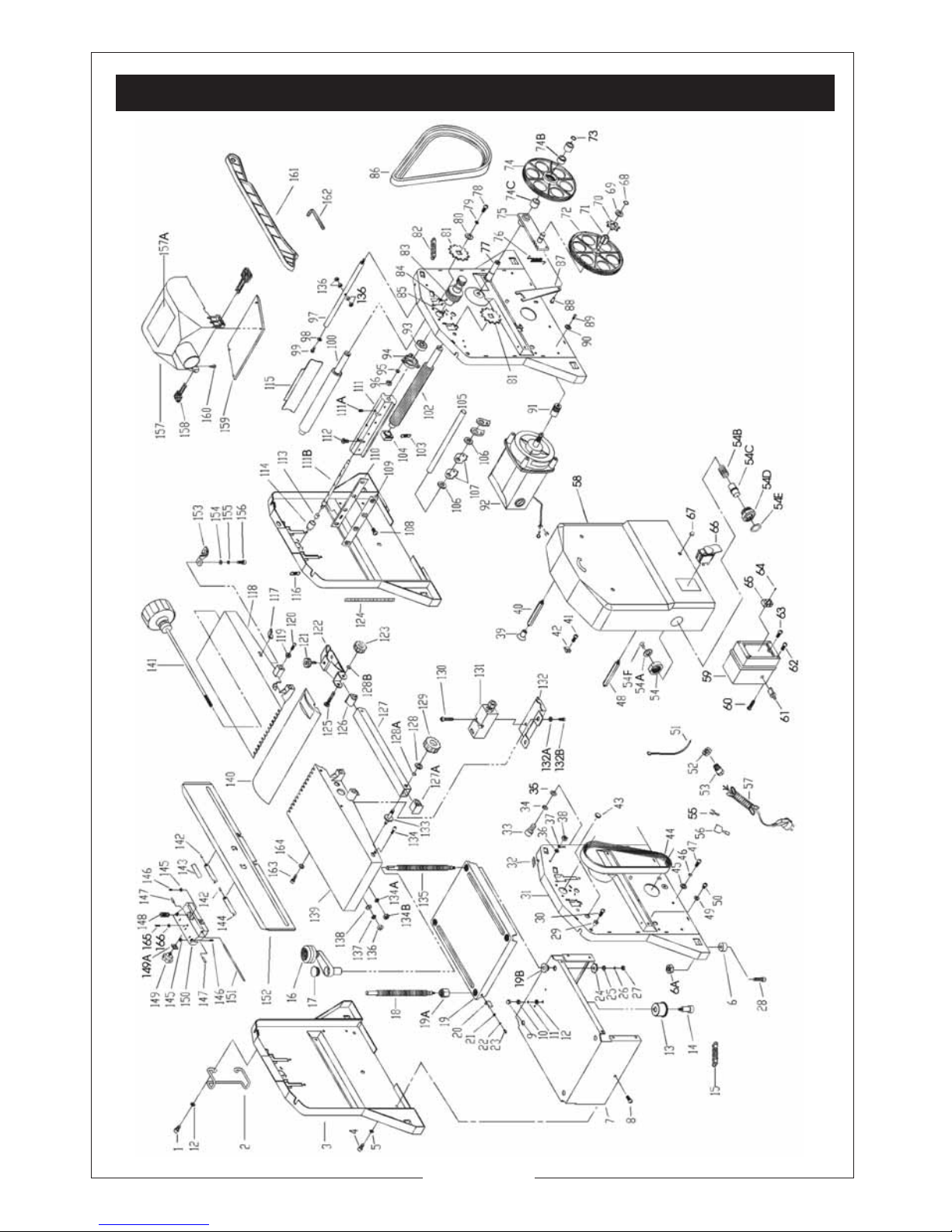
CPT800
Exploded Diagram &
Parts List
Page 20
20
SPARE PARTS DIAGRAM - CPT800
Page 21

21
PARTS LIST - CPT800
No. Description Qty Part No. No. Description Qty Part No.
1 Bolt NXCPT8001
2 Cord Stowage Bkt NXCPT8002
3 Side Plate Top NXCPT8003
4 Bolt NXCPT8004
5 Locking Washer NXCPT8005
6 Rubber Buffer NXCPT8006
6A Nut NXCPT8006A
7 Motor Covering NXCPT8007
8 Bolt NXCPT8008
9 Nut NXCPT8009
10 Locking Washer NXCPT8010
11 Washer NXCPT8011
12 Angle NXCPT8012
13 Angle NXCPT8013
14 Screw NXCPT8014
15 Chain NXCPT8015
16 Crank NXCPT8016
17 Plug NXCPT8017
18 Threaded Spindle,Short NXCPT8018
19 Table NXCPT8019
19A Threaded Spindle Nut NXCPT8019A
19B Sleeve NXCPT8019B
20 Pointer NXCPT8020
21 Locking Washer NXCPT8021
22 Washer NXCPT8022
23 Bolt NXCPT8023
24 Chain Wheel NXCPT80324
25 Washer NXCPT8025
26 Locking Washer NXCPT8026
27 Hexagonal Nut NXCPT8027
28 Bolt NXCPT8028
29 Sleeve NXCPT8029
30 Bolt NXCPT8030
31 Side Plate ,Left NXCPT8031
32 Cutting Depth Scale NXCPT8032
33 Bolt NXCPT8033
34 Locking Washer NXCPT8034
35 Washer NXCPT8035
36 Washer NXCPT8036
37 Locking Washer NXCPT8037
38 Hexagonal Nut NXCPT8038
39 Bolt NXCPT8049
40 Rod,Long NXCPT8040
41 Bolt NXCPT8041
42 Cable Clamp NXCPT8042
43 Rubber Buffer NXCPT8043
44 Flat Belt NXCPT8044
45 Washer NXCPT8045
46 Locking Washer NXCPT8046
47 Bolt NXCPT8047
48 Rod,Long NXCPT8048
49 Washer NXCPT8049
50 Bolt NXCPT8050
52 Plastic Locknut NXCPT8052
53 Strain Relief NXCPT8053
54 Nut NXCPT8054
54A Washer NXCPT8054A
54B Spring NXCPT8054B
54C Plunger NXCPT8054C
54D Reset Assy. NXCPT8054D
54E Label NXCPT8054E
54F Screw NXCPT8054F
55 Locking Line NXCPT8055
56 Rubber Set NXCPT8056
57 Power Cable NXCPT8057
58 Protecting Hood NXCPT8058
59 Switch Box NXCPT8059
60 Bolt NXCPT8060
61 Thermo-protector NXCPT8061
62 Bolt NXCPT8062
63 Bolt NXCPT8063
64 Bolt NXCPT8064
65 Terminal NXCPT8065
66 Switch NXCPT8066
67 Nut NXCPT8067
68 Locking Ring NXCPT8068
69 Washer NXCPT8069
70 Chain Wheel NXCPT8070
71 Square Sleeve NXCPT8071
72 Gear Wheel NXCPT8072
73 Locking Ring NXCPT8073
74 Large Belt Wheel NXCPT8074
74B Bush NXCPT8074B
74C Needle Bearing NXCPT8074C
75 Pivot Plate NXCPT8075
76 Retracting Spring NXCPT8076
77 Arbor NXCPT8077
78 Bolt NXCPT8078
Page 22

22
No. Description Qty Part No. No. Description Qty Part No.
79 Locking Washer NXCPT8079
80 Washer NXCPT8080
81 Chain Wheel NXCPT8081
82 Chain NXCPT8082
83 Small Belt Wheel NXCPT8083
84 Bolt NXCPT8084
85 Bolt NXCPT8085
86 Flat Belt NXCPT8086
87 Supporting Plate NXCPT8087
88 Post NXCPT8088
91 Motor Belt Wheel NXCPT8091
92 Motor NXCPT8092
93 Grooved Ball Bearing NXCPT8093
94 Bearing Cover NXCPT8094
95 Locking Washer NXCPT8095
96 Hexagonal Nut NXCPT8096
97 Strut NXCPT8097
98 Washer NXCPT8098
99 Bolt NXCPT8099
100 Feed-out Roller NXCPT8100
102 Feed-in Roller NXCPT8102
103 Retracting Spring NXCPT8103
104 Bearing Bush NXCPT8104
105 Rod NXCPT8105
106 Washer NXCPT8106
107 Kick Back Pawl NXCPT8107
108 Bolt NXCPT8108
109 Clamping Block NXCPT8109
110 Cutter Blade NXCPT8110
111 Cutter Block NXCPT8111
111A Bolt NXCPT8111A
111B Arbor NXCPT8111B
112 Bolt NXCPT8112
113 Needle Bearing NXCPT8113
114 Bearing Cap NXCPT8114
115 Sheet Metal Deflector NXCPT8115
116 Retracting Spring NXCPT8116
117 Pointer NXCPT8117
118 Front Table Top NXCPT8118
119 Sliding Block NXCPT8119
120 Bolt NXCPT8120
121 Hand Knob NXCPT8121
122 Blade Cover Holder NXCPT8122
123 Hand Knob NXCPT8123
124 Scale NXCPT8124
125 Stud Bolt NXCPT8125
126 Cover NXCPT8126
127 Square Tube NXCPT8127
127A Cover NXCPT8127A
128 Washer NXCPT8128
128A Locking Ring NXCPT8128A
128B Locking Ring NXCPT8128B
129 Hand Knob NXCPT8129
130 Bolt NXCPT8130
131 Limit Switch NXCPT8131
132 Switch Cover NXCPT8132
132A Washer NXCPT8132A
132B Bolt NXCPT8132B
133 Stud Bolt NXCPT8133
134 Stop NXCPT8134
134A Lock Washer NXCPT8134A
134B Nut NXCPT8134B
135 Threaded Spindle - Long NXCPT8135
136 Hex. Nut NXCPT8136
137 Locking washer NXCPT8137
138 Washer NXCPT8138
139 Rear table top NXCPT8139
140 Cutter Guard NXCPT8140
141 Spindle NXCPT8141
142 Rod - Short NXCPT8142
143 Angle instruction 1 NXCPT8143
144 Angle instruction 2 NXCPT8144
145 N ut NXCPT8145
146 Bolt NXCPT8146
147 Pin NXCPT8147
148 Bolt NXCPT8148
149 Hand Knob NXCPT8149
149A Nut NXCPT8149A
150 Angle Piece NXCPT8150
151 Stalk,Long NXCPT80151
152 Guide Fence NXCPT8152
153 Clamp NXCPT8153
154 Washer NXCPT8154
155 Locking Washer NXCPT8155
156 Bolt NXCPT8156
157 Dust Collector NXCPT8157
157A Label NXCPT8157A
158 Key Assembly NXCPT8158
159 Cover NXCPT8169
160 Bolt NXCPT8160
161 Push Stick NXCPT81161
162 Hex Wrench NXCPT8162
Page 23

23
For Spare Parts and Service, please contact your nearest dealer,
or CLARKE International, on one of the following numbers.
PARTS & SERVICE TEL: 020 8988 7400
PARTS & SERVICE F AX: 020 8558 3622
or e-mail as follows:
PARTS: [email protected]
SERVICE: [email protected]
PARTS & SERVICE CONTACTS
IMPORTANT:
The use of parts other than CLARKE replacement parts may result in safety hazards,
decreased tool performance and may invalidate your warranty.
Page 24

24
 Loading...