

Page 1

ANGLE GRINDER
MODEL NO: CON1150
PART NO: 6474015
OPERATING & MAINTENANCE
INSTRUCTIONS
ORIGINAL INSTRUCTIONS GC0518-ISS 1
Page 2
INTRODUCTION
Thank you for purchasing this CLARKE Angle Grinder.
Your Angle Grinder has been designed to give long and trouble free service. If
you encounter problems, return the unit to your local CLARKE dealer.
Before attempting to use this product, please read this manual thoroughly and
follow the instructions carefully.
WARNING: THIS SYMBOL IS USED THROUGHOUT THE USER GUIDE WHEN
THERE IS A RISK OF PERSONAL INJURY. MAKE SURE THAT THESE WARNINGS
ARE READ AND UNDERSTOOD AT ALL TIMES.
CAUTION: THIS SYMBOL IS USED THROUGHOUT THE USER GUIDE WHEN
THERE IS A RISK OF DAMAGE TO THE PRODUCT. MAKE SURE THAT THESE
CAUTIONS ARE READ AND UNDERSTOOD AT ALL TIMES.
GUARANTEE
This product is guaranteed against faulty manufacture for a period of 12
months from the date of purchase. Please keep your receipt which will be
required as proof of purchase.
This guarantee is invalid if the product is found to have been abused or
tampered with in any way, or not used for the purpose for which it was
intended.
Faulty goods should be returned to their place of purchase, no product can
be returned to us without prior permission. This guarantee does not effect your
statutory rights.
ENVIRONMENTAL RECYCLING POLICY
Through purchase of this product, the customer is taking on the
obligation to deal with the WEEE in accordance with the WEEE
regulations in relation to the treatment, recycling & recovery and
environmentally sound disposal of the WEEE.
In effect, this means that this product must not be disposed of with general
household waste. It must be disposed of according to the laws governing
Waste Electrical and Electronic Equipment (WEEE) at a recognised disposal
facility.
2
Parts & Service: 020 8988 7400 / E-mail: [email protected] or [email protected]
Page 3
SAFETY SYMBOLS
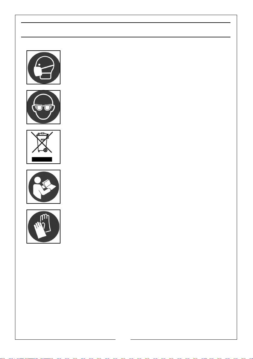
The following safety symbols may be found on the machine.
Wear dust mask
Wear eye protection
Falls within WEEE Directive (see page 2)
Read instruction manual before use
Wear hand protection
3
Parts & Service: 020 8988 7400 / E-mail: [email protected] or [email protected]
Page 4

GENERAL SAFETY RULES
CAUTION: FAILURE TO FOLLOW THESE PRECAUTIONS COULD RESULT IN
PERSONAL INJURY, AND/OR DAMAGE TO PROPERTY.
WORK ENVIRONMENT
1. Keep the work area clean and well lit. Cluttered and dark areas invite
accidents.
2. Do not operate power tools in explosive atmospheres, such as in the
presence of flammable liquids, gases or dust. Power tools create sparks
which may ignite the dust or fumes.
3. Keep children and bystanders away while operating a power tool. Anyone
entering the work area must wear personal protective equipment.
Distractions can cause you to lose control and fragments of work or a
broken disc may fly away and cause injury.
4. Store power tools properly when not in use. Abrasive products should be
stored in a dry, secure place out of the reach of children.
ELECTRICAL SAFETY
1. Power tool plugs must match the outlet. Never modify the plug in any way.
Do not use adapter plugs with earthed (grounded) power tools. Unmodified
plugs and matching outlets will reduce the risk of electric shock.
2. Do not expose power tools to rain or wet conditions. Water entering a
power tool will increase the risk of electric shock.
3. Do not abuse the cable. Never use the cable for carrying, pulling or
unplugging the power tool. Keep the cable away from heat, oil, sharp
edges or moving parts. Damaged or entangled cables increase the risk of
electric shock.
4. When operating a power tool outdoors, use an extension cable suitable for
outdoor use. Use of a cable suitable for outdoor use reduces the risk of
electric shock.
PERSONAL SAFETY
1. Stay alert, watch what you are doing and use common sense when
operating a power tool. Do not use a power tool while you are tired or
under the influence of drugs, alcohol or medication. A moment of
inattention while operating power tools may result in personal injury.
4
Parts & Service: 020 8988 7400 / E-mail: [email protected] or [email protected]
Page 5

2. Use personal protective equipment. Always wear eye protection. Safety
equipment such as dust mask, non-skid safety shoes, hand protection and
a workshop apron capable of stopping small abrasive or workpiece
fragments.
3. Avoid accidental starting. Ensure the switch is in the off position before
plugging in. Carrying power tools with your finger on the switch or plugging
in power tools that have the switch on invites accidents.
4. Remove any adjusting key or wrench before turning the power tool on. A
wrench or a key left attached to a rotating part of the power tool may
result in personal injury.
5. Do not overreach. Keep proper footing and balance at all times. This
enables better control of the power tool in unexpected situations.
6. Dress properly. Do not wear loose clothing or jewellery.
7. Keep your hair, clothing and gloves away from moving parts. Loose
clothes, jewellery or long hair can be caught in moving parts. Keep the
work area clean and tidy.
8. This tool vibrates with use. Vibration may be harmful to your hands or arms.
Stop using the tool if discomfort, a tingling feeling or pain occurs. Seek
medical advice before resuming use.
9. Hold the power tool by insulated gripping surfaces only, when performing
an operation where the cutting tool could contact hidden wiring or its own
cable. Contacting a live wire may make exposed parts of the power tool
live and give the operator an electric shock.
10. Never lay a power tool down until it has come to a complete standstill. The
rotating accessory may grab the surface and pull the tool out of your
control.
11. Do not run the power tool while carrying it at your side. Accidental contact
with a spinning accessory could snag on clothing and pull the tool to your
body.
12. Regularly clean the power tool’s air vents. The motor fan will draw dust
inside the housing and accumulation of material could cause electrical
hazards.
13. Avoid operator fatigue. Stop the power tool at regular intervals for a short
break to rest hands and arms.
14. Maintain your tools. Keep all handles and grips dry and clean.
5
Parts & Service: 020 8988 7400 / E-mail: [email protected] or [email protected]
Page 6

ANGLE GRINDER SAFETY INSTRUCTIONS
1. Before starting work, always consider the following: The use of hand held
angle grinders for grinding and cutting operations can present risks to the
user. Full observation of the safety instructions in this user guide is essential.
2. Before undertaking grinding or cutting operations, always consider the
following: Is the grinding/cutting work necessary? Could a different tool be
used with less risk? (e.g. a fixed controlled cutting/grinding machine). Can
the work be sensibly positioned, secured and accessed so the operator
can maintain adequate control of the tool, taking into account, for
example the possible hazards associated with potential snatch/jamming of
a cutting disc. Is the cutting task too large for a hand held tool? If in doubt,
use an alternative lower risk solution or refer to qualified trade personnel.
3. Always use the correct tool for the job. Always assess the job. You should
never force a small angle grinder to do the job of a duty heavy tool. Do not
use tools for purposes not intended.
4. Always position the power cable clear of the spinning disc. If you loose
control, the cable may be cut or snagged and your hand drawn onto the
spinning disc.
5. Start up speed. Always allow the angle grinder to run up to full operating
speed before applying it to the job.
6. Applying the disc to the workpiece. Never bump the angle grinder disc on
the workpiece, or let the disc hit any other objects while grinding.
7. Do not abuse the mains lead. Never carry the tool by the mains lead or pull
it to disconnect it from the mains socket. Keep the mains lead away from
heat, oil and sharp edges.
8. Secure the work. Use clamps or vices to hold the workpiece. Failure to
secure the workpiece could result in serious injury.
9. Remove adjusting keys and wrenches. Form the habit of checking to see
that keys and adjusting wrenches are removed from the tool before
turning it on.
10. Use outdoor extension leads. When the tool is used outdoors, only use
extension leads intended for outdoor use. Always make sure that the
extension lead is correctly rated.
11. Check damaged parts. A guard or other parts that are damaged should
be properly repaired or replaced by an authorised service centre, unless
otherwise indicated in this user guide. Have defective switches replaced
by an authorised service centre.
6
Parts & Service: 020 8988 7400 / E-mail: [email protected] or [email protected]
Page 7

12. Accessories. Only use the recommended accessories. Ensure that the discs
are fitted in accordance with the manufacturer’s instructions.
13. Only use discs that comply with EN12413 or EN13236. Make sure that the
disc used is suitable for the no load speed of the angle grinder. See
Specifications on page 16. Check that the speed marked on the disc is
compatible with the grinder. Check that discs are specifically for hand held
angle grinder use.
14. Sparks and particles. Ensure that sparks and particles resulting from use do
not create a hazard, use screens where appropriate.
15. Personal protective equipment. Always use protective safety glasses and
dust mask. Use other protective equipment such as gloves, apron and
helmet where necessary. If working at floor level, always wear knee pads.
16. Switching off. The disc will continue to rotate for a few seconds after the
angle grinder is switched off. Always wait until the disc has completely
stopped before putting the angle grinder down.
17. Use the disc guard. Do not use the angle grinder without the disc guard.
Make sure that the guard is securely fitted and positioned for maximum
safety before operating the angle grinder. Always use the correct guard for
cutting or grinding work as described in this manual.
18. The grinding surface of depressed centre discs must be mounted below
the plane of the guard lip. An improperly mounted discthat projects above
the plane of the guard lip cannot be adequately protected.
19. Holding the angle grinder. Always hold the angle grinder with both hands.
Ensure that the workpiece is kept at waist height where possible. Never use
the angle grinder between the legs whilst sitting on the floor.
20. Feed direction. For cutting, always feed the disc into the work so that an
upcutting action is achieved.
21. Spindle lock. Do not operate the spindle lock while the spindle is still
spinning.
22. Beware of kickback. Always take care to avoid kickback by maintaining a
firm grip of the tool and positioning your body and arm to resist kickback
forces. Always use the auxiliary handle for maximum control.
23. Avoid moving parts. Never position your hand close to the rotating parts
and take special care when working in corners or with sharp edges, or any
situation where the disc could snag.
7
Parts & Service: 020 8988 7400 / E-mail: [email protected] or [email protected]
Page 8

DISC SAFETY INSTRUCTIONS
1. Disc speed. Check the speed of the disc before fitting to your angle
grinder. Never use a disc with a guaranteed rpm speed less than the rpm
speed of your angle grinder. See specification on page 16.
2. The outside diameter and thickness of your accessories must be within the
capacity rating of the power tool. The correct size accessories can be
correctly guarded and controlled.
3. Inspect the disc before fitting. Never use a disc that is chipped, cracked or
damaged. Fragments from a broken or damaged disc can cause serious
injury. Make sure that defective discs are destroyed and not used.
4. Handling and mounting discs. Bonded abrasive products are breakable
and shall therefore be handled with utmost care. The use of damaged or
improperly mounted or used abrasive products is dangerous and can
cause serious injuries.
5. Disc usage. Always refer to the label for specified usage and observe the
safety information. Do not use for purposes other than specified. Discs for
wet cutting applications must not be used with this angle grinder.
6. Use the correct disc. Always use the correct disc for it’s intended task. Using
the wrong disc can cause serious injury.
7. Using the disc. Allow the disc and tool to do the work. Never force the disc
onto the workpiece as this could cause kickback and/or shatter the disc
causing serious injury. Kickback can occur in the event of a disc jam.
8. Cutting discs. Do not use cutting discs for side grinding. Do not put
sideways pressure on cutting discs.
9. Do not use reducing bushes. Do not use separate reducing bushes or
adapters to adapt large hole abrasive discs. Do not force a disc onto a
grinding machine or alter the size of the arbor hole.
10. Never use a damaged disc. Inspect each disc before each use for chips,
cracks, excess wear. If the tool or accessory is dropped, inspect for
damage or install a new accessory. After fitting the accessory, position
yourself away from the plane of the rotating accessory and run the tool at
full speed. damaged discs are likely to break apart during this test.
11. Handling and storing discs. Abrasive products shall be handled and
transported with care. Abrasive products shall be stored in such a manner
that they are not subjected to mechanical damage and harmful
environmental influences.
12. Always use suitable mounting discs. Ensure they are of the correct size and
shape for your cutting or grinding disc to support the disc and reduce the
possibility of breakage.
8
Parts & Service: 020 8988 7400 / E-mail: [email protected] or [email protected]
Page 9
ELECTRICAL CONNECTIONS
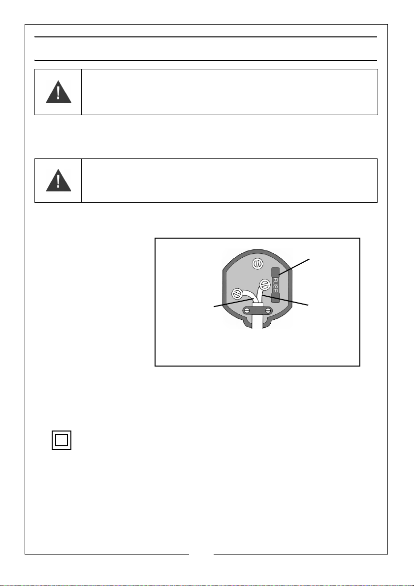
Plug must be BS1363/A approved.
Always fit
make sure that the outer sheath of
Neutral
(Blue)
Live
(Brown)
a 13 Amp
the cable is firmly held by the clamp
fuse.
WARNING: READ THESE ELECTRICAL SAFETY INSTRUCTIONS FULLY
BEFORE CONNECTING THE MACHINE TO THE MAINS SUPPLY.
This product is provided with a standard 13 amp, 230 volt (50Hz), BS 1363 plug,
for connection to a standard, domestic electrical supply. Should the plug
need changing, make sure that a plug of identical specification is used.
WARNING: THE WIRES IN THE CABLE ARE COLOURED AS FOLLOWS:
BLUE = NEUTRAL BROWN = LIVE
If the colours of the wires in the power cable do not correspond with the
markings on the terminals of your plug, proceed as follows.
• Connect the blue
wire to the
terminal which is
marked N.
• Connect the
brown wire to the
terminal which is
marked L.
AN APPROVED RESIDUAL CURRENT DEVICE (RCD) WHICH HAS A TRIPPING
CURRENT OF LESS THAN 30mA MUST BE USED.
If you are not sure, consult a qualified electrician. DO NOT try to do any
repairs.
This symbol indicates that this is a Class II product, and does not require an
earth connection.
Parts & Service: 020 8988 7400 / E-mail: [email protected] or [email protected]
9
Page 10
OVERVIEW
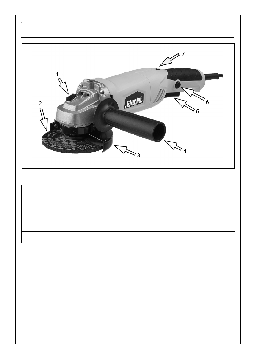
NO DESCRIPTION NO DESCRIPTION
1 Spindle Lock Button 5 Trigger
2 Grinding/Cutting Disc 6 Trigger Safety Lock Button
3 Disc Guard 7 Speed Controller
4 Auxiliary Handle
When unpacking, check for damage or shortages etc. Any found should be
reported to your CLARKE dealer where the product was originally purchased.
The CON1150 is supplied with the following loose components:
•2 x Disc Guards
• 1 x Grinding Disc
• 1 x Pin Spanner
• 1 x Handle
• 2 x Securing Discs
• Pair Carbon Brushes
10
Parts & Service: 020 8988 7400 / E-mail: [email protected] or [email protected]
Page 11
BEFORE USE
SELECTING THE CORRECT GUARD
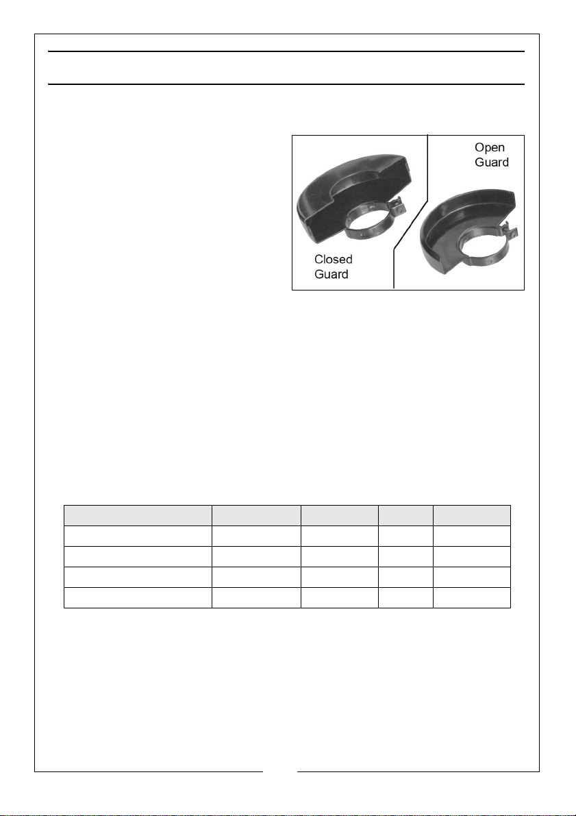
Both open and a closed guard are
supplied with the CON1150.
The “open” guard is for grinding and
the “closed” one is for cutting.
The open guard should be used with
type 27, 28 and 29 discs as follows;
• Type 27 - Depressed centre
grinding discs
• Type 28 - Depressed centre
grinding discs cone shaped
• Type 29 - Depressed centre semi-flexible discs
The closed guard should be used with type 1, 41 & 42 discs as follows;
• Type 1 - Straight grinding discs
• Type 41 - Flat cutting off discs
• Type 42 - Depressed centre cutting off discs.
SELECTING SUITABLE ABRASIVE AND CUTTING DISCS
The following Clarke discs are suitable for use with the CON1150. Always use
the correct disc and guard type for its intended task.
Use Model No Diameter Bore Part No
Cutting & Grinding PD1 (plasma) 115 mm 22 mm 3052050
Metal Cutting ----------------- 115 mm 22 mm 6470775
Metal Grinding ----------------- 115 mm 22 mm 6470705
Masonry Cutting ----------------- 115 mm 22 mm 6470735
11
Parts & Service: 020 8988 7400 / E-mail: [email protected] or [email protected]
Page 12
FITTING/ADJUSTING THE DISC GUARD
WARNING: MAKE SURE THAT THE ANGLE GRINDER IS SWITCHED OFF AND
UNPLUGGED FROM THE MAINS SUPPLY BEFORE FITTING OR REMOVING
ANY ACCESSORIES. ENSURE THE CORRECT GUARD IS FITTED FOR THE DISC
BEING USED.
WARNING: THE DISC GUARD SHOULD BE FITTED SO THAT IT PROVIDES
MAXIMUM PROTECTION TO THE USER WHEN IN THE WORKING POSITION.
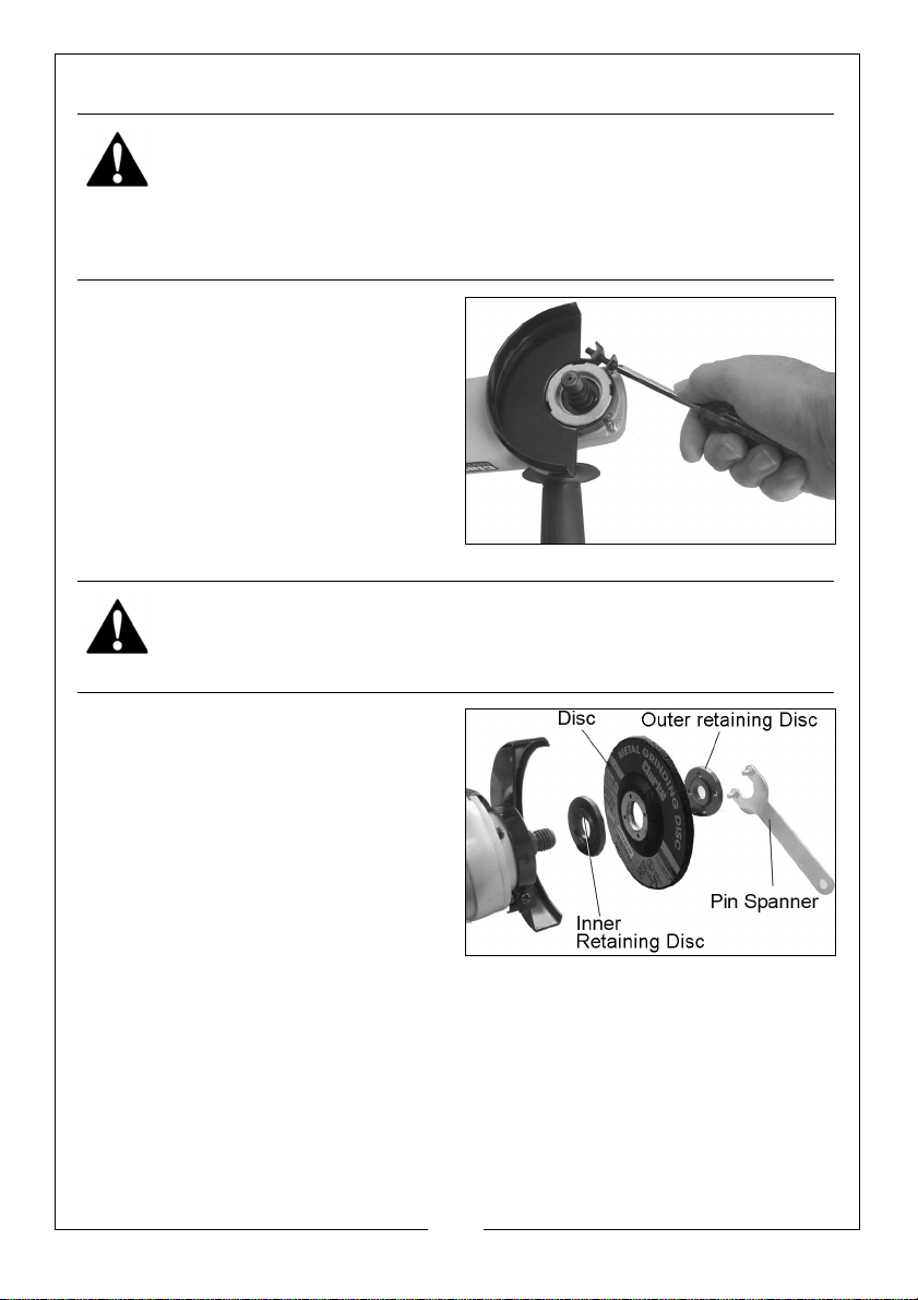
1. Slide the disc guard into place as
shown.
2. Rotate the disc guard to the
required position and secure by
tightening the screw.
3. Ensure the disc guard is securely
fitted before using the grinder.
FITTING/REMOVING A DISC
WARNING: MAKE SURE THAT THE ANGLE GRINDER IS SWITCHED OFF AND
UNPLUGGED FROM THE MAINS SUPPLY BEFORE FITTING OR REMOVING
ANY ACCESSORIES.
Make sure the correct disc guard is
fitted before you fit any cutting or
grinding disc.
1. Press and hold the spindle lock
button.
• You will need to turn the spindle
by hand to fully engage the
spindle lock.
2. Use the pin spanner supplied to
remove the outer retaining disc.
3. Ensure the inner retaining disc is fitted correctly, with the raised “flats” on
the inner side engaging with the corresponding flat section on the spindle.
4. Place the grinding disc over the spindle and on top of the inner retaining
disc.
• If the grinding discs supplied is a depressed centre type, mount it as
shown, i.e. with the depressed centre (printed side) towards the
machine.
12
Parts & Service: 020 8988 7400 / E-mail: [email protected] or [email protected]
Page 13
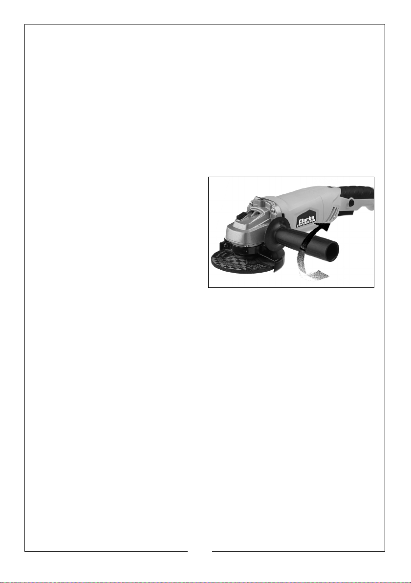
• For standard discs make sure that the raised centre section of the
outer retaining disc is pointing towards the grinding disc
5. Screw on the outer retaining disc with the raised section facing inwards so
as to sit inside the aperture of the disc. Tighten securely with the pin
spanner.
• When using thin discs, the outer retaining disc can be reversed so
that the raised section is pointing away from the grinding disc.
6. With the spindle lock engaged, use the pin spanner to tighten the outer
retaining disc. Care should be taken also NOT to overtighten.
FITTING THE AUXILIARY HANDLE
1. Fit the auxiliary handle by
screwing it into the threaded hole
on either the top, left or right hand
side of the angle grinder.
13
Parts & Service: 020 8988 7400 / E-mail: [email protected] or [email protected]
Page 14
OPERATION
WARNING: FRAGMENTS FROM A BROKEN/DETACHED DISC CAN CAUSE
SERIOUS INJURY.
WARNING: WHEN USING CUTTING DISCS, DO NOT STAND DIRECTLY IN
LINE WITH THE ROTATING DISC.
WARNING: DO NOT PUT LATERAL PRESSURE ON CUTTING DISCS.
WARNING: ENSURE THAT THE WORKING POSITION ADOPTED DOES NOT
CAUSE OPERATOR FATIGUE WHICH MAY LEAD TO LOSS OF CONTROL OF
THE CUTTING DISC AND IMPACT/SNATCH WITH SURROUNDING OBJECTS.
WARNING: ENSURE THE INTENDED CUTTING PATH IS CLEAR AND WITH
SUFFICIENT CLEARANCE BETWEEN SURROUNDING OBJECTS.
WARNING: WHEN CUTTING, KEEP THE ANGLE GRINDER STRAIGHT TO
PREVENT SNATCHING OR JAMMING OBJECTS.
WARNING: ALWAYS FIT THE CORRECT GUARD ACCORDING TO WHETHER
A CUTTING OR GRINDING DISC IS BEING USED. REFER TO PAGE 11.
SWITCHING ON/OFF
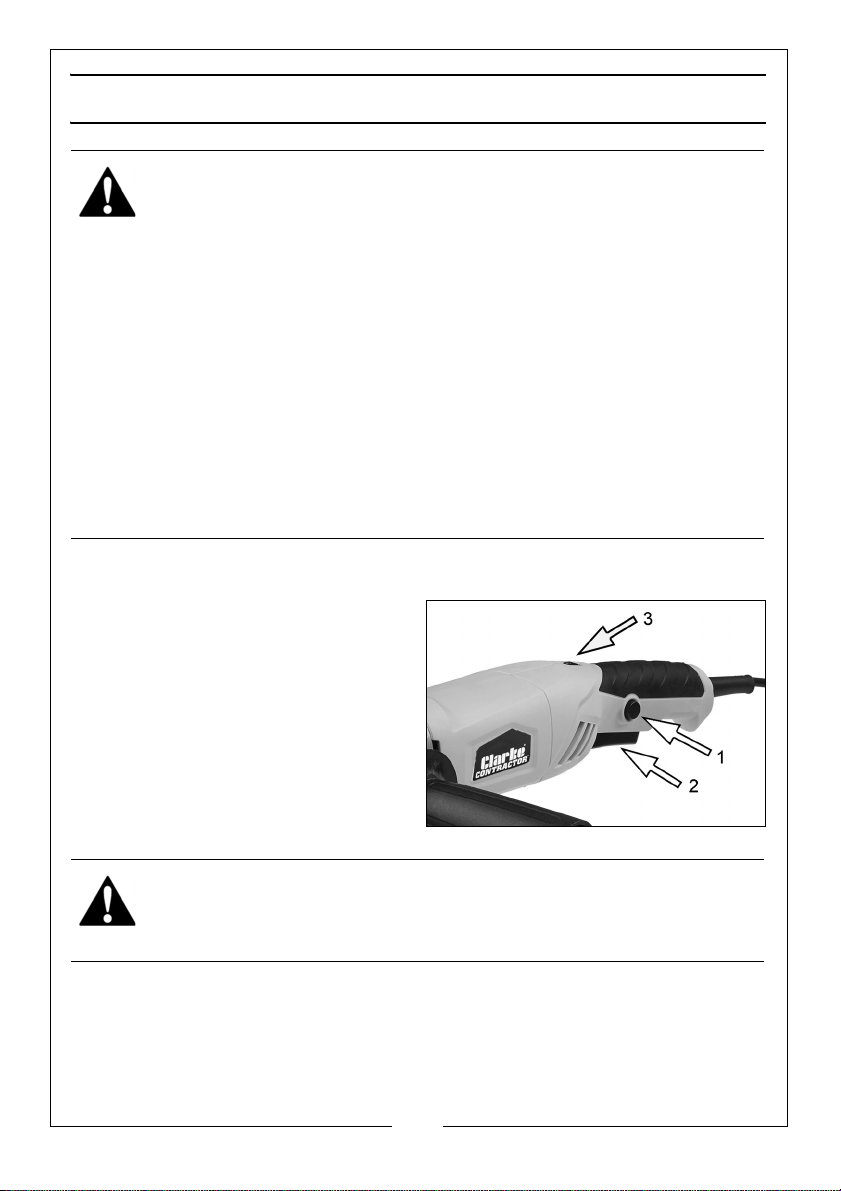
1. To start the angle grinder, press
and hold the safety button (1)
and squeeze the trigger (2).
• The disc will start instantly.
Always maintain a firm grip with
both hands.
2. To stop the angle grinder, release
the trigger.
3. Set your chosen speed by rotating
the speed control wheel (3).
WARNING: THE DISC WILL CONTINUE TO ROTATE FOR A FEW SECONDS
AFTER THE TRIGGER HAS BEEN RELEASED.
CUTTING TIPS
• Do not force the disc through the material. Work with a feed rate
that is suited to the material being cut.
• Do not subject the cutting disc to sideways pressure.
14
Parts & Service: 020 8988 7400 / E-mail: [email protected] or [email protected]
Page 15
• The direction of the cutting motion is important. Always feed the
cutting disc into the work so that it cuts in an upward direction. If you
do not do this it can result in the disc climbing out of the cut in an
uncontrolled manner and may lead to loss of control or serious injury.
• Whenever a new disc has been fitted, always run the grinder at no
load speed to check for irregularities before starting work.
GRINDING TIPS
WARNING: WHEN GRINDING, ONLY USE DISCS SPECIFICALLY DESIGNED
FOR GRINDING. YOU MUST NEVER USE CUTTING DISCS TO GRIND ANY
MATERIAL.
• The key to efficient grinding is to control the pressure and surface
contact between the grinding disc and the workpiece.
• Flat surfaces are ground at an acute angle, usually 15 to 30 degrees
to the workpiece. Too great an angle causes concentration of
pressure on a small area which may gouge, or burn the workpiece.
• Allow the disc to reach full speed before grinding.
• Avoid overloading the angle grinder. If it becomes hot when being
used, allow it to run for a few minutes under no-load conditions.
MAINTENANCE
GENERAL MAINTENANCE
1. Always have your angle grinder inspected and maintained by qualified
service personnel. Do not attempt to repair the angle grinder unless you
are qualified to do so.
2. Make sure that all nuts, bolts and screws are tight and secure.
3. Check the side handle and the guard for damage.
4. Always have any damaged, or worn parts repaired or replaced.
5. Ensure the grinding or cutting disc is perfectly sound, free from cracks or
damage.
6. Inspect the power cable to ensure it is sound and free from cracks or bare
wires etc.
CLEANING
To maintain the best possible performance from your angle grinder, it must be
kept clean.
15
Parts & Service: 020 8988 7400 / E-mail: [email protected] or [email protected]
Page 16
1. Ensure all air ventilation slots are clear, (use compressed air to clean the
machine if possible. Always wear protective goggles when cleaning with
compressed air).
2. Clean the product with a soft cleaning cloth. Never use any chemicals or
harsh abrasives. Avoid using solvents when cleaning plastic parts, which
may be susceptible to damage from various types of commercial solvents.
3. After extensive use the carbon brushes in the drive motor may require
replacement and a spare pair are provided for fitting by your dealer.
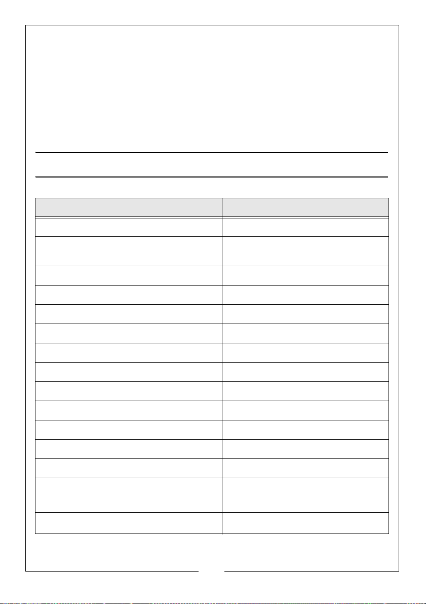
SPECIFICATIONS
Model Number CON1150
Dimensions (L x W x H) 400 x 130 x 104 mm
Weight 2.35 kg with open guard fitted
2.48 kg with closed guard fitted
Power Supply 230V - 50Hz
Input Power 1150 W
Abrasive Disc Diameter (max) 115 mm
Abrasive Disc thickness 6 mm
Abrasive Disc Bore 22 mm
Spindle Thread Size M14
Speed Range (step-less/10% tolerance) 3000 to 11,000 rpm
Duty Cycle S1 (continuous)
Sound Pressure Level (LpA dB) 89.7 dB(A)
Sound Power Measured (LwA dB) 100.97 dB(A)
Uncertainty 3 dB
Vibration Emissions
8.685 m/s
2
(Main Handle)
7.890 m/s2 (Aux Handle)
Uncertainty value
1.5 m/s
2
16
Parts & Service: 020 8988 7400 / E-mail: [email protected] or [email protected]
Page 17
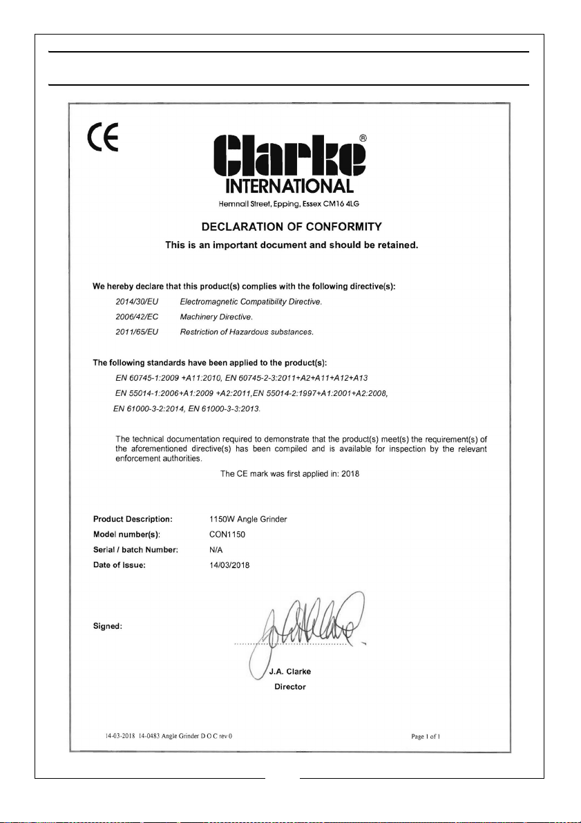
DECLARATION OF CONFORMITY
17
Parts & Service: 020 8988 7400 / E-mail: [email protected] or [email protected]
Page 18
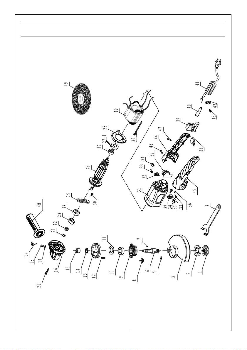
PARTS LIST & DIAGRAM
18
Parts & Service: 020 8988 7400 / E-mail: [email protected] or [email protected]
Page 19
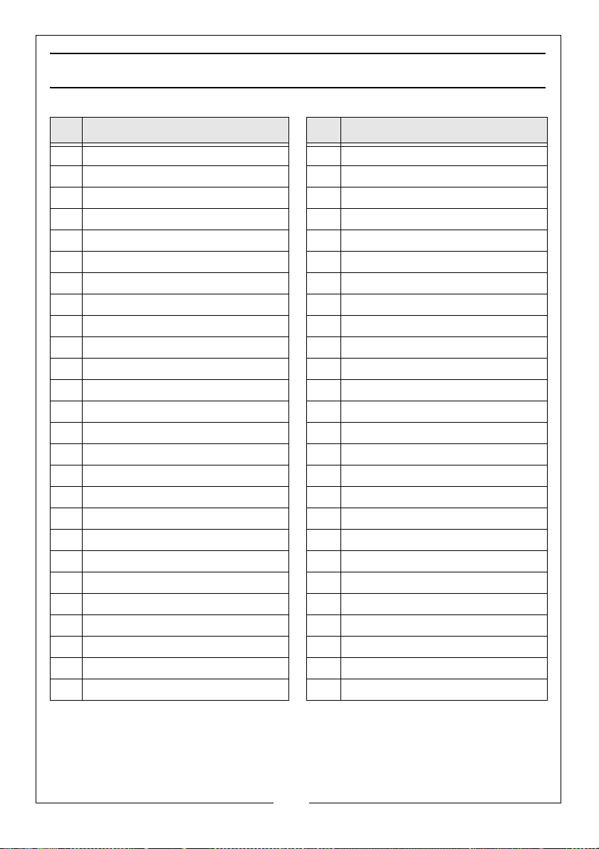
PARTS LIST
No Description No Description
1 Outer Retaining Disc 27 Bearing 607
2 Inner Retaining Disc 27-1 Leather Collar 607
3 Safety Guard 28 Baffle
4 Pin Spanner 29 Stator
5 Screw M5 x 16 30 Cross head ST Screw M4x70
6 Spindle 31 Housing
7 Woodruffe Key 32 Carbon Brush Holder
8 Cross head Screw M4x14 33 Spring
9 Front Cover 34 Carbon Brush
10 Bearing 6201 35 Cross head ST Screw M3x10
11 Bearing retainer 36 Cross head ST Screw/gasket
12 Cross head Screw M4x10 37 Speed Controller
13 Primary Gear 38 Capacitor
14 Circlip 10mm 39 Switch
15 Copper Bush 40 Cable Sleeve
16 Gearbox 41 Power Cable
17 Split Washer 5mm 42 Cable Clamp
18 Spindle Lock Spring 43 Cross head ST Screw M4x12
19 Spindle Lock 44 Right Handle
20 Cross head ST Screw M4x25 45 Left Handle
21 Nut M8 46 Cross head ST Screw M4x30
22 Spring Washer 8mm 47 Cross head ST Screw M4x16
23 Secondary Gear 48 Side Handle
24 Bearing 629 49 Disc
25 Bearing retainer 50 Machine Screw
26 Rotor
19
Parts & Service: 020 8988 7400 / E-mail: [email protected] or [email protected]
Page 20

Page 21

 Loading...