

Page 1
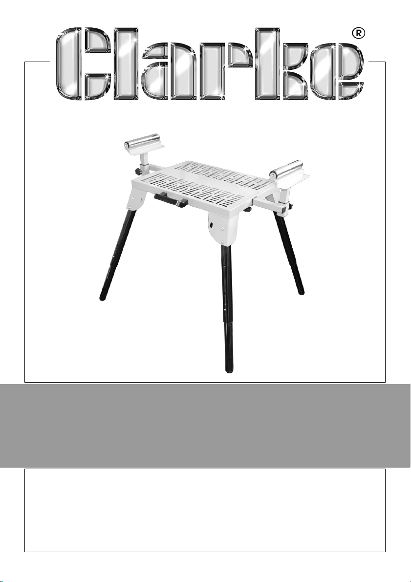
MITRE SAW STAND WITH ROLLERS
MODEL NO: CMSSR
PART NO: 6500975
ASSEMBLY INSTRUCTIONS
ORIGINAL INSTRUCTIONS
LS0718 - ISS 2
Page 2

INTRODUCTION
Thank you for selecting this Clarke mitre saw stand with rollers.
Read this manual before use, the warnings and cautions in this manual will
help you use the mitre saw stand safely.
GUARANTEE
This product is guaranteed against faulty manufacture for a period of 12
months from the date of purchase. Please keep your receipt which will be
required as proof of purchase.
This guarantee is invalid if the product is found to have been abused or
tampered with in any way, or not used for the purpose for which it was
intended.
Faulty goods should be returned to their place of purchase, no product can
be returned to us without prior permission.
This guarantee does not effect your statutory rights.
SAFETY PRECAUTIONS
1. This mitre saw stand has a maximum load capacity of 15O kg which must
not be exceeded.
2. Do not stand on top of the mitre saw stand.
3. Take care when placing a load on to the mitre saw stand, it should be
placed gently so that the strain is taken up gradually. Do not drop a load
carelessly.
4. Always check the mitre saw stand for damage before use.
5. Always ensure you are working on a firm flat stable surface.
SPECIFICATIONS
Maximum Dimensions 1710 (fully extended) x 460 x 595-820 mm
Maximum Load 150 kg
2
Parts & Service: 020 8988 7400 / E-mail: [email protected] or [email protected]
Page 3
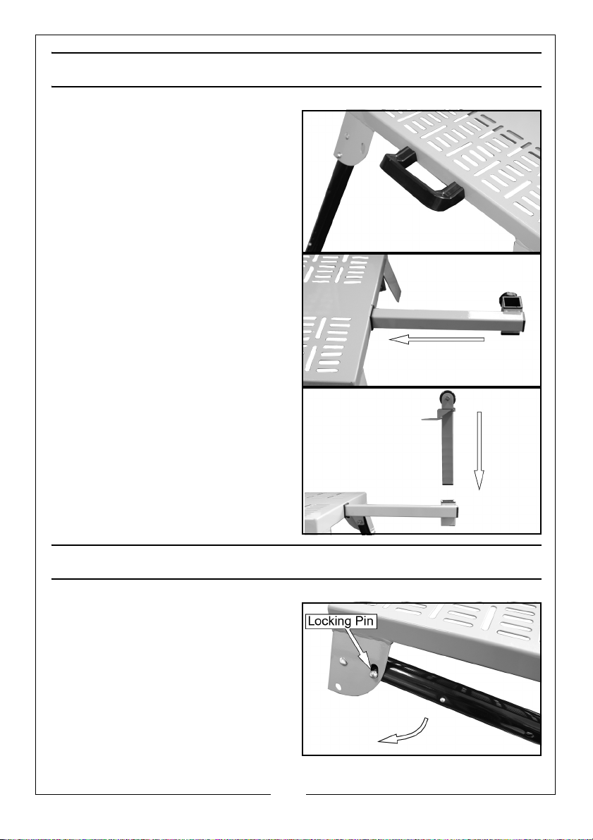
ASSEMBLY
1. Screw the handle onto the table
using the screws provided.
2. Slide in the extension arms and
secure from below using the knob
supplied.
3. Insert the rollers into the extension
arms and secure in place using
the knob supplied.
OPENING/CLOSING THE MITRE SAW STAND
1. Push the locking pin in as you
swing the leg into position.
2. The leg should lock into place.
3. Test the stability of the table
before use.
3
Parts & Service: 020 8988 7400 / E-mail: [email protected] or [email protected]
Page 4
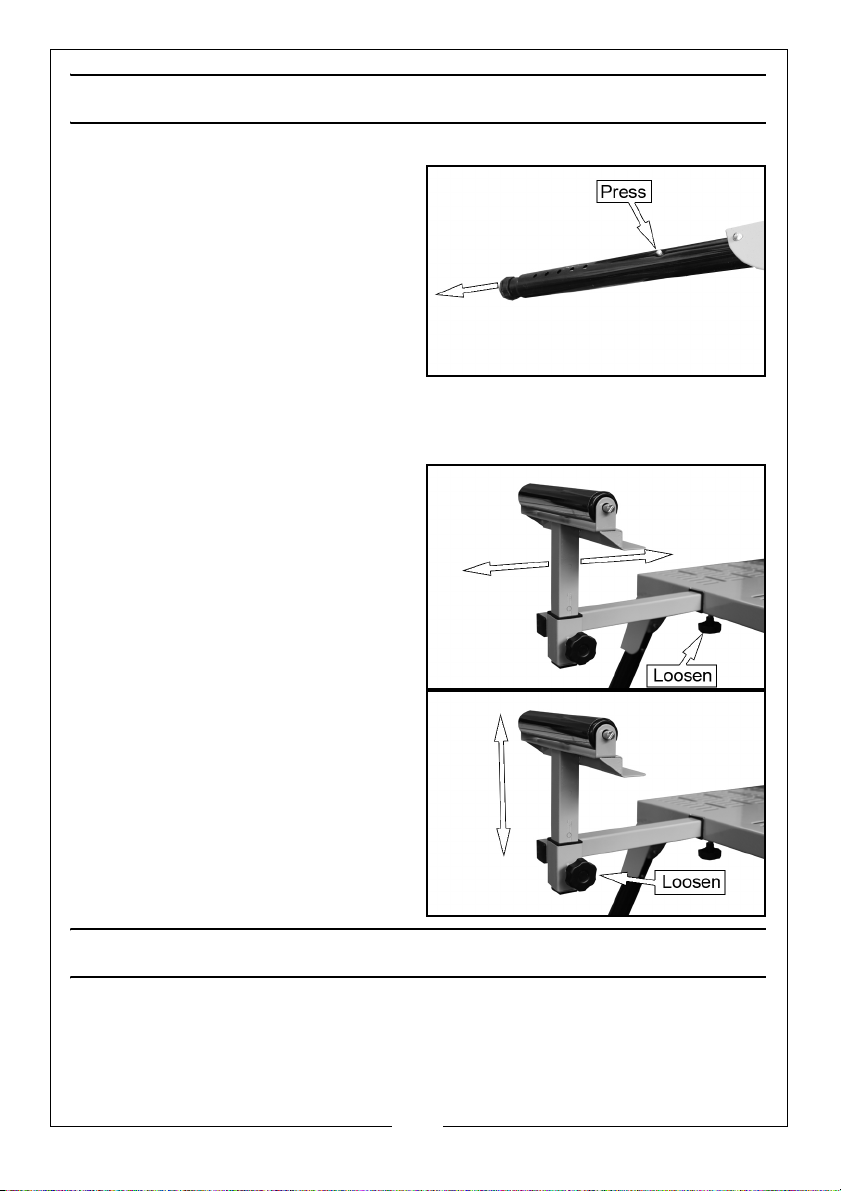
ADJUSTING THE MITRE SAW STAND
ADJUSTING THE LEG HEIGHT
1. Press the locking pin shown and
pull the leg to the desired height.
• The locking pin must lock into
one of the holes on the leg.
• Make sure that the same hole is
used on each leg.
2. Repeat steps 1 to 3 with the
remaining legs.
3. Test the stability of the table before use.
ADJUSTING THE ROLLER LENGTH
1. Loosen the knob shown.
2. Slide the extension arm to the
required position.
3. Tighten the knob to lock in place.
ADJUSTING THE ROLLER HEIGHT
1. Loosen the knob shown.
2. Adjust the roller to the required
height.
3. Tighten the knob to lock in place.
ATTACHING THE MITRE SAW
1. Place the mitre saw in the middle of the table and secure to the table
using the fixings supplied.
4
Parts & Service: 020 8988 7400 / E-mail: [email protected] or [email protected]
 Loading...