

Page 1
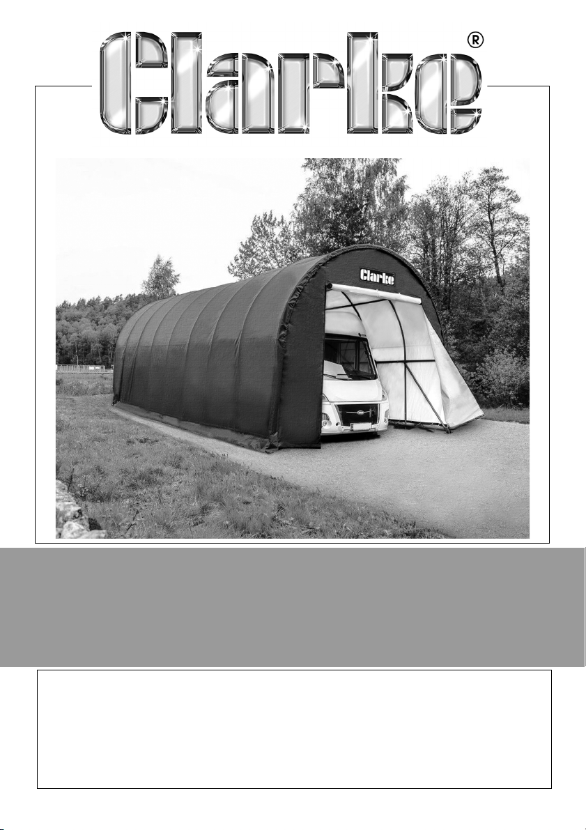
X-LARGE GARAGE/WORKSHOP
MODEL NO: CIG1432
PART NO: 3503594
ASSEMBLY INSTRUCTIONS
ORIGINAL INSTRUCTIONS GC0422 - Rev 1
Page 2
INTRODUCTION
Thank you for purchasing this CLARKE X Large Garage/Workshop.
Before attempting to use this product, please read this manual thoroughly and
follow the instructions carefully. In doing so you will ensure the safety of yourself
and that of others around you, and you can look forward to your purchase
giving you long and satisfactory service.
SPECIFICATIONS
Roof Cover Polyethylene, UV protected, 305 gsm
1/4” dia braided nylon rope
1” wide X 0.055” thick woven straps (inside end of
cover)
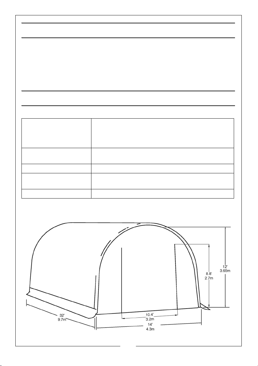
Assembled dimensions 30 ft long x 14 ft wide x 12 ft high
(9.7 m long x 4.3 m wide x 3.65 m high
Frame Round steel tubing, 1-1/2” dia x 0.055”wall thickness
Securing hardware Steel ratchets (tie down top straps), elastic cord/ball
ties
Weight 267 kgs.
2
Parts & Service: 020 8988 7400 / E-mail: [email protected] or [email protected]
Page 3
GENERAL SAFETY WARNINGS
WARNING: READ THESE SAFETY INSTRUCTIONS TO REDUCE THE RISK OF
INJURY. RETAIN THESE INSTRUCTIONS FOR FUTURE REFERENCE.
DO NOT use this product in environments for which it is not Intended (i.e.
extreme cold, high winds, extreme heat, heavy rainfall, etc).
DO NOT use open flames or cooking or heating devices inside or in close
proximity to the garage including all types of stoves, gas heaters, gas lanterns,
electric heaters, torches, fly killers, etc. The fabric will burn if left in continuous
contact with a naked flame.
DO NOT store flammable liquids (petrol, kerosene, propane, etc.) in the
garage or operate gas powered vehicles/equipment in or around the
garage.
ALWAYS follow the following instructions for mounting the garage.
Due to the height of this garage, an aerial platform or cherry picker will be
useful and safer than using ladders. Ensure that any such platforms or ladders
are operated on level ground.
We advise that 4 to 6 people may be required to safely erect the frame and
install the cover owing to the size and weight.
Select a calm day to install the cover due to the high windage of the cover
both during fitting and before it is totally secured in position.
POSITIONING AND INSTALLATION OF THE GARAGE
POSITIONING THE GARAGE
This garage is a temporary structure and is not recommended as a permanent
building. It is designed to offer protection from sun, rain, light snow, tree sap
and bird droppings etc. It is not designed to shelter equipment from
excessively high winds or heavy snow.
Choose your garage location carefully. Check for overhead power lines, tree
branches, etc. DO NOT install near roofs or other structures that may shed snow,
ice or excessive run-off onto your garage.
SITING THE GARAGE
Erect your garage on level ground over a firm, level area. Allow enough
space near each corner for the tie-down straps supplied to be used as
3
Parts & Service: 020 8988 7400 / E-mail: [email protected] or [email protected]
Page 4
intended. If the ground area is of tarmac or concrete, the use of ground
anchor holding-down bolts will be required to anchor the garage to the floor.
Choose a dry location where dampness rising from ground water in the
environment will not undermine the protection offered by the garage.
A masonry floor such as block paving or concrete is ideal, but if this is not
being supplied, a timber or shuttering plywood floor, protected by a suitable
groundsheet should be used. This will help to create a dry storage environment
by insulating the garage storage space from ground moisture.
Proper anchoring and keeping the cover tight and free of snow and debris is
the responsibility of the user. Damage caused by improper anchoring is not
covered under warranty.
CARE OF THE GARAGE STRUCTURE
This garage is NOT designed to support heavy snow. Snow or ice accumulation
may cause your garage to collapse. To avoid overload, use a ladder to brush
snow and ice off the roof top with a broom or mop to prevent collapse with
the resultant damage to property or personal injury.
NEVER clear the roof of snow or debris from inside the garage.
DO NOT use hard-edged tools or instruments, such as rakes or shovels to
remove snow. These can cause punctures to the cover.
DO NOT use bleach, alkaline or harsh detergents for cleaning. Doing so will
damage the material. Soap and warm water are recommended.
In order to reduce risk of burning and avoid damage, DO NOT- cook, smoke,
refuel or use any open flame devices in or around the garage.
USING THE STORAGE SPACE
NEVER run the engine of any vehicle or machine inside a closed garage.
Ensure that there is adequate ventilation for engines or for any work with
paints, cleaners. etc. by opening the door panel and keeping it raised.
CONDENSATION
Take steps to avoid the buildup of condensation inside the garage. Cool,
damp winter days and moisture from the breath and body heat of personnel
may cause condensation on the inside of the top cover of the garage.
A supply of fresh air through the doorway will at least partly remove this issue.
For long term storage of moisture sensitive belongings in all weathers, the use
of a Dehumidifier may be required, such as those in the CLARKE range.
4
Parts & Service: 020 8988 7400 / E-mail: [email protected] or [email protected]
Page 5
A suitable extension lead to a locally available power supply will be required.
Condensation will be much less of an issue during the summer months.
If storing a vehicle in your garage over the winter months we recommend the
use of a secondary lightweight cover over your vehicle.
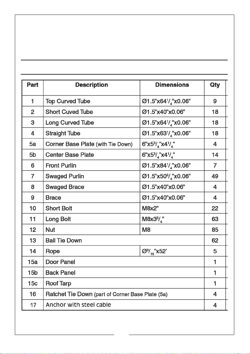
COMPONENT PARTS INVENTORY
5
Parts & Service: 020 8988 7400 / E-mail: [email protected] or [email protected]
Page 6

ASSEMBLY
WARNING: DO NOT PLACE THE PRODUCT UNDER TREES FROM WHICH
HARD FRUIT SUCH AS APPLES, WALNUTS OR HEAVY PINE CONES, ETC.,
MAY FALL. KEEP CHILDREN AWAY DURING ASSEMBLY. DO NOT ATTEMPT
TO ASSEMBLE THE PRODUCT IF ANY PARTS ARE MISSING. DO NOT LEAVE
THE GARAGE UNATTENDED DURING ASSEMBLY IN CASE PERSONAL
INJURY OR DAMAGE MAY OCCUR
Have an overview of all parts before attempting construction and make sure
all components are supplied. Note: Some parts are listed but are not available
individually as replacement parts.
1. Place all parts boxes in the center of the base pad area. Open each parts
box labeled "1" through "4" and group each type of part. If parts are not
labeled, mark the part number on each item.
2. Remove all packaging materials and place them back in the box. Do not
dispose of the packaging materials until assembly is complete
PREPARATION
1. Select the location for the garage.
2. Make sure that at least six people are available to assemble this product.
3. The foundation should be a concrete slab, concrete footings, pressure
treated timbers or railway sleepers. The foundation area or pad area must
extend at least 6 inches (15cm) larger than the size of the garage. See
examples below.
.
4. If possible, pick a location for the garage that has a natural or man-made
wind break (eg barn, house hedge or hill etc). Level the pad area and
clear of any debris.
5. Bring the following tools (not supplied) to the assembly site:
• Screwdrivers
• Adjustable wrench
• Ladder(s)/cherry picker lift or platform
MOUNTING FRAME TUBES, PIPES, AND PURLINS
During this part of the garage assembly, it will progress faster if others help in
the process. Also, refer to the Assembly Drawing and Parts List at the start of this
manual for guidance.
1. Fit the Straight Vertical Tubes (4) over the Base Plates (5a and 5b) and align
the lower mounting holes. See illustration below.
6
Parts & Service: 020 8988 7400 / E-mail: [email protected] or [email protected]
Page 7
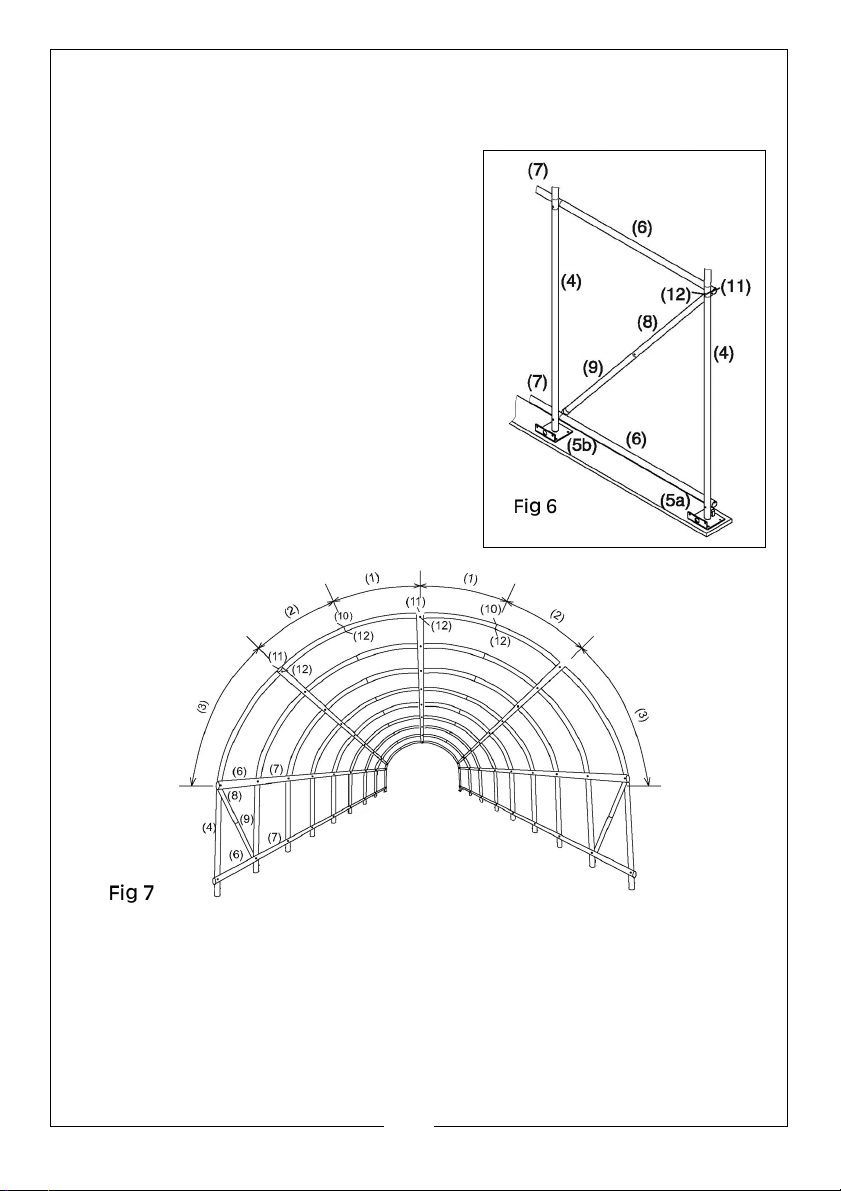
2. Connect the Brace (9) & Swaged Brace (8) together. Attach a Brace (9)
and Front Purlin (6) to the first Straight Tube (4) at the Base Plate (5a/b),
using long bolt (11) and nut (12).
3. Insert the tapered end of a Swaged
Purlin (7) into the end of the Front Purlin
(6) and secure using a long bolt (11) and
nut (12). Continue assembling purlins in
this way to the end of the structure, then
attach a Brace (9) between the last
Purlin (7) and Straight Tube (4), using a
long bolt (11) and nut (12).
4. Repeat steps 1 and 2 at the end of this
row.
NOTE: In the entire assembly, all bolts must
be mounted from the outside-in, so
that the roof cover (15c) will not be
damaged by the bolt ends.
5. Assemble and secure three arches at a
time. Refer to the illustration following.
• Lay out three Roof Curved Tubes (1), six Short Curved Tubes (2), and
six Long Curved Tubes (3).
• Insert the Short Curved tubes (2) into each end of the Roof Curved
tubes (1). Align the screw holes and secure with Short Bolt (10) and
Nut (12).
• Insert the Long Curved Tubes (3) into the Short Curved Tubes (2).
Align screw holes.
7
Parts & Service: 020 8988 7400 / E-mail: [email protected] or [email protected]
Page 8
• With the help of two other people, lift the completed arch and insert
it into the Straight Vertical Tube (4) on each side. Do the same with
the other two arches.
• Using a ladder to reach the arch, attach Front Purlin (6), then Purlin
(7) under the arches using long bolts (11) and nuts (12). Do this in
three places each side. Securely tighten.
6. Repeat step 5, assembling the balance of the arches.
7. When the frame is completed check all nuts and bolts for tightness.
ANCHORING INSTRUCTIONS
IMPORTANT: Due to its size, the garage needs
to be anchored down very securely and the
frame needs to be tight and secure.
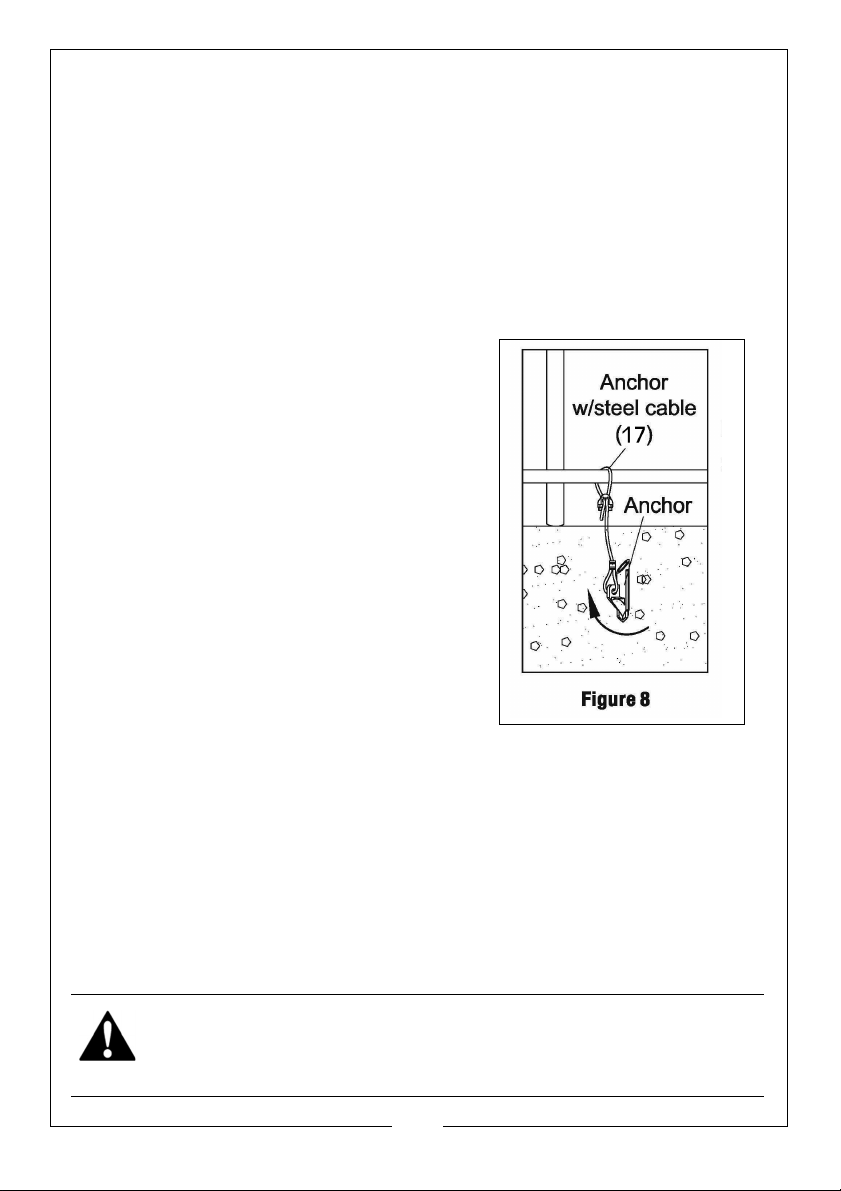
1. From the inside of the garage, place the
anchors with Steel Cable (17) on all four
corners. Place the remainder of the
anchors on the inside of the bows at
intervals. See Figure 8.
NOTE: Additional anchors may be required
in windy areas.
2. If you are installing on asphalt, drill a deep
1” diameter hole to accept the anchor
through the asphalt.
3. If installing in dirt, drive the anchor into the
soil using a hammer and the drive rod
provided. The more you hammer, the
more the anchor goes into the soil,
compacting the soil around it. Remove the drive rod once you have
established the maximum depth of the anchor.
4. Pull upwards on the cable, rotating the anchor into a locked position. The
anchor cuts into the undisturbed soil.
5. After placing all the anchors, wrap the wire cable from each anchor,
around the Bottom Rails and securely attach it to itself using clamps (25)
(not shown). See Figure 8.
NOTE: If you are in any doubt as to the security of anchoring of your
garage you should add more anchors.
WARNING: ADEQUATE ANCHORING IS ESSENTIAL. IF YOU HAVE ANY
DOUBT AS TO THE SECURITY OF THE GARAGE ADD MORE ANCHORS.
8
Parts & Service: 020 8988 7400 / E-mail: [email protected] or [email protected]
Page 9
COVER PLACEMENT/TIE DOWN
1. Place a protective cover on the ground to one side of the frame.
2. Unfold the roof cover onto the protective cover with the eyelets next to the
sill plate. The inside of the cover should be facing up. Do not step on the
cover.
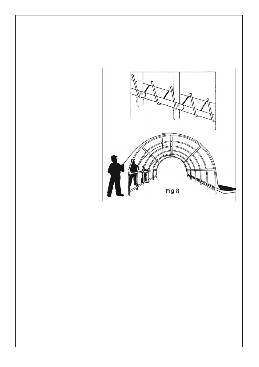
3. Weave the rope (14)
through each eyelet
and around the Front
Purlin (6), and the rest
of the purlins (7). Refer
to the illustration on the
top of the next page
When weaving, leave
about 1/2 inch between
the Roof Cover and the
bottom purlins.
4. After weaving the rope
(14), tie down the rope
to the end Base Plates.
CAUTION: TAKE CARE NOT TO
TEAR THE ROOF COVER
EYELETS OUT OF THE FABRIC.
5. Tie the other ropes
(14) to the center and
end eyelets on the other side of the cover.
6. Throw the ropes over the top of the frame to the other side. See illustration
above.
7. With the help of two others, carefully pull the Roof Cover over the frame.
Keep the cover centered on the frame while pulling it over. It may help to
have others guide the feeding of the cover from where it is lying.
CAUTION: DO NOT TEAR THE ROOF COVER. IF THE ROOF COVER CATCHES ON
PART OF THE FRAME, STOP PULLING THE ROPES. GET ON A LADDER AND UNDO THE
CATCH. IF IT HAPPENS TO BE A BOLT PLACED UPSIDE DOWN, REVERSE THE BOLT
MOUNTING BEFORE PROCEEDING.
8. With the roof cover completely over the frame, weave the rope (14)
through each eyelet and around the Front Purlin (6), and the rest of the
purlins (7). as shown in the illustration above.
.
9
Parts & Service: 020 8988 7400 / E-mail: [email protected] or [email protected]
Page 10
9. After weaving the rope (14), tie down the
rope to the end frame.
10. Attach the Split Door Panel (15a) to the front
entrance of the garage using Ball Tie Downs
(13) through each eyelet.
11. Attach the Solid End Panel (15b) to the back
of the garage using Ball Tie Downs (13)
though each eyelet.
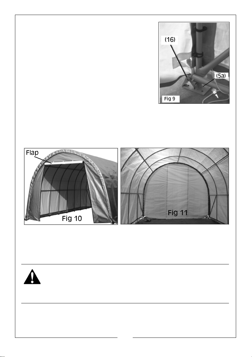
12. Attach the Ratchet Tie Down (16) to each
corner.
13. At each corner of the roof cover is a flat strap.
Feed the flat strap through the front (and back) covers, into the Ratchet Tie
Down (16) and begin to tighten the each ratchet alternately, a little at a
time. When this happens, the 6 inch roof skin flap will fold over the frame
ends as shown below-left.
14. Check periodically (two to three times in the first week) and tighten the
ratchet tie-downs and all hardware as needed. You may need to remove
and re-set the ratchet to allow for more strap material becoming wound
around the ratchet spindle.
WARNING: IF POSITIONING THE GARAGE IN A WINDY LOCATION
ALWAYS ENSURE THE FRONT DOOR IS KEPT FULLY CLOSED TO PREVENT
WIND LIFTING IT FROM INSIDE.
WARNING: SERIOUS INJURY TO PERSONS OR PROPERTY COULD RESULT IF
THE GARAGE IS NOT SECURELY ANCHORED.
NOTE: If you are in any doubt as to the security of anchoring of your
garage you should add more anchors.
10
Parts & Service: 020 8988 7400 / E-mail: [email protected] or [email protected]
Page 11
DISASSEMBLY
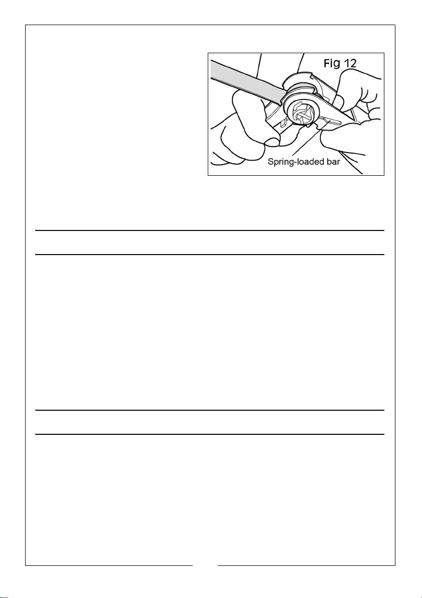
When disassembling the garage
depress the spring-loaded bar to
disengage the ratchet and open
the ratchet handle completely to
allow the webbing strap to pull
through.
PLEASE RE-READ ALL WARNINGS ON
PAGE 2 OF THESE INSTRUCTIONS.
To dismantle, execute all instructions
in reverse order.
Store your garage in a cool, dry
location between seasons to prolong the usable life of all components.
Components are not equally durable and will require replacement over time
at differing intervals.
MAINTENANCE
1. The cover can be cleaned with soap and water.
2. For best performance, keep all parts of this product clean and dry.
3. Check periodically (two to three times in the first week) and tighten the
turnbuckles and all hardware as needed. You may need to remove and reset the turnbuckles to allow for more strap material becoming wound
around the spindle.
4. To dismantle, execute all instructions in reverse order.
5. Store your garage in a cool, dry location between seasons to prolong the
usable life of all components. Components are not equally durable and
will require replacement over time at differing intervals.
GUARANTEE
This product is guaranteed against faulty manufacture for a period of 12
months from the date of purchase. Please keep your receipt which will be
required as proof of purchase.
This guarantee is invalid if the product is found to have been abused or
tampered with in any way, or not used for the purpose for which it was
intended.
Faulty goods should be returned to their place of purchase, no product can
be returned to us without prior permission. This guarantee does not effect your
statutory rights.
11
Parts & Service: 020 8988 7400 / E-mail: [email protected] or [email protected]
Page 12

 Loading...