

Page 1
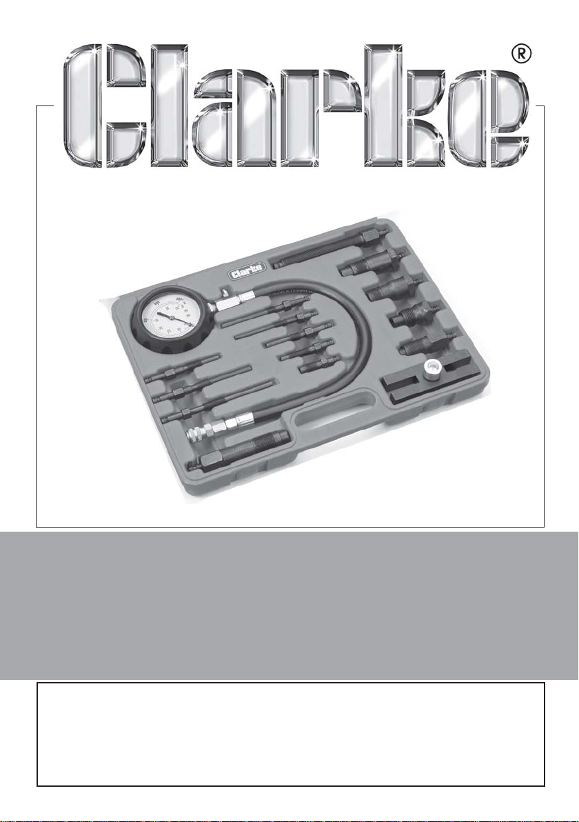
DIESEL ENGINE CYLINDER
LEAKAGE KIT
Model No: CHT703
Part No: 1801703
USER INSTRUCTIONS
GC06/12
Page 2
INTRODUCTION
Thank you for purchasing this CLARKE product. This compression testing kit
includes fittings suitable to replace the injectors and glow plugs in a diesel
engine. Refer to the table below for details of fittings and thread patterns.
Please read and follow the instructions carefully. In doing so you will ensure
the safety of yourself and others around you, and you can look forward to
the product giving you long & satisfactory service.
Please keep these instructions in a safe place for future reference
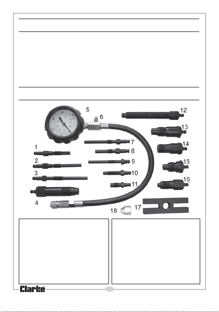
KIT CONTENTS
1 Glow Plug Adaptor 91mm M10x1
2 Glow Plug Adaptor 119mm M10x1
3 Glow Plug Adaptor 135mm M10x1.25
4 Glow Plug Adaptor 118mm M22x1.5
5 Pressure Gauge
6 Bleed Valve/Hose
7 Glow Plug Adaptor 113mm M10x1
8 Glow Plug Adaptor 102mm M8x1
9 Glow Plug Adaptor 83mm M10x1
Parts & Service: 020 8988 7400/E-mail:[email protected] or [email protected]
10 Glow Plug Adaptor 64mm M10x1.25
11 Glow Plug Adaptor 47mm M12x1.25
12 Special Adaptor
13 Injector Adaptor 88mm M24x1.5
14 Injector Adaptor 73mm M22x1.5
15 Injector Adaptor 63mm M24x2
16 Injector Adaptor 75mm M20x1.5
17 Bridge Fitting
18 Tapered Adaptor Cone
2
Page 3
METHOD OF USE
WARNING: ALWAYS KEEP HANDS WELL AWAY FROM HOT/MOVING
ENGINE PARTS. TAKE CARE TO KEEP THE KIT COMPONENTS FROM
BECOMING ENTANGLED IN MOVING ENGINE PARTS. ENSURE ALL TEST
COMPONENTS ARE FULLY SECURE BEFORE PLACING THE ENGINE UNDER
COMPRESSION.
BEFORE USE
Identify the size of adaptor that is required for the engine to be tested.
The vehicle battery and starting system must be in good condition to ensure
an accurate test.
USING THE KIT
1. Allow the engine to reach normal working temperature.
2. Stop the engine, remove all the glow plugs or injectors (refer to vehicle
manufacturer’s manual).
3. Disconnect the fuel shut-off solenoid to disable the fuel injection pump.
4. Screw the pressure gauge/hose (with the correct adaptor attached) into
a glow plug/injector hole. Ensure the fitting is screwed in securely.
The special adaptor (12) is used together with the tapered adaptor cone
(18) and bridge fitting (17) when the injector/glow plug ports are not
suitable. Suitable attachment bolts (not supplied) will be required.
5. With the throttle in the wide open position, turn the engine over 6-8
revolutions. The gauge (5) will automatically record the pressure reached.
6. To release the pressure and re-set the gauge, depress the button on the
bleed valve (6).
7. The components can now be unscrewed and the next cylinder tested.
MAINTENANCE
Always keep the components clean. Ensure that screw threads do not
become dirty. If necessary, clean with a stiff brush.
GUARANTEE
This product is guaranteed against faulty manufacture for a period of 12
months from the date of purchase. Please keep your receipt which will be
required as proof of purchase.This guarantee is invalid if the product is found
to have been abused or tampered with in any way, or not used for its
intended purpose. Faulty goods should be returned to their place of
purchase. No product can be returned to us without prior permission. This
guarantee does not effect your statutory rights.
3
Parts & Service: 020 8988 7400/E-mail:[email protected] or [email protected]
Page 4
 Loading...