

Page 1
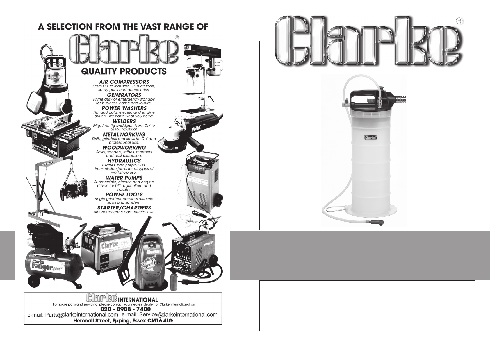
PNEUMATIC OIL EXTRACTOR
PNEUMATIC OIL EXTRACTOR
Model No. CHT588
Part No. 1801588
USER INSTRUCTIONS
1106
Page 2
Thank you for purchasing this CLARKE Air Operated Oil Extractor
Before attempting to use this equipment, please read these instructions thoroughly
and follow the instructions carefully. In doing so you will ensure the safety of yourself
and that of others around you, and you can look forward to the equipment giving
you long and satisfactory service.
CLARKE GUARANTEE
This CLARKE product is guaranteed against faulty manufacture for a period
of 12 months from the date of purchase. Please keep your receipt as proof
of purchase.
This guarantee is invalid if the product is found to have been abused or
tampered with in any way, or not used for the purpose for which it was
intended.
Faulty goods should be returned to their place of purchase, no product
can be returned to us without prior permission.
This guarantee does not effect your statutory rights.
SPECIFICATIONS
Model No: ......................................................... CHT588
Part No: ............................................................. 1801588
Working Pressure .............................................. 5 - 12bar MAX (70 - 170psi)
Air Inlet .............................................................. 1/4” BSP
Container Capacity ........................................ 5.5 Litres
Air Consumption .............................................. 5cfm
Please note that the details and specifications contained herein, are correct at the time of going to print. However,
CLARKE International reserve the right to change specifications at any time without prior notice.
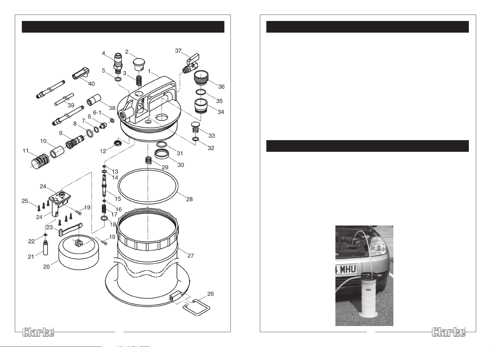
PARTS LIST
No: Description Qty Part No:
1 Cover Housing 1 HTCHT58801
2 Push Button 1 HTCHT58802
3 Spring 1 HTCHT58803
4 Fluid Inlet Coupler 1 HTCHT58804
5 O-Ring 1 HTCHT58805
6 Vacuum Valve 1 HTCHT58806
7 O-Ring 1 HTCHT58807
8 O-Ring 1 HTCHT58808
9 Vacuum Body 1 HTCHT58809
10 Air Silencer Insert 1 HTCHT58810
11 Air Silencer Body 1 HTCHT58811
12 Lock Nut 1 HTCHT58812
13 O-Ring 1 HTCHT58813
14 O-Ring 1 HTCHT58814
15 Shaft 1 HTCHT58815
16 O-Ring 1 HTCHT58816
17 Spring 1 HTCHT58817
18 O-Ring 1 HTCHT58818
19 Pin 2 HTCHT58819
20 Float 1 HTCHT58820
21 Safety Cup 1 HTCHT58821
22 O-Ring 1 HTCHT58822
23 Arm 1 HTCHT58823
24 Safety Valve Housing 1 HTCHT58824
25 Screw 6 HTCHT58825
26 Foot Tread 1 HTCHT58826
27 Tank 1 HTCHT58827
28 Packing 1 HTCHT58828
29 Spring 1 HTCHT58829
30 Lock Nut 1 HTCHT58830
31 O-Ring 1 HTCHT58831
32 O-Ring 1 HTCHT58832
33 Safety Valve 1 HTCHT58833
34 Fluid Outlet Housing 1 HTCHT58834
35 O-Ring 1 HTCHT58835
36 Fluid Outlet Cover 1 HTCHT58836
37 Air Valve 1 HTCHT58837
38 Main Suction Tube w/Adapter 1 HTCHT58838
39 Extracting Tube 1 HTCHT58839
40 Soft Tube Rubber Fitting 1 HTCHT58840
6-1 O-Ring 1 HTCHT58841
2
7
Page 3
PARTS DIAGRAM
FOR YOUR OWN SAFETY
• DO NOT exceed the maximum safe working air pressure as stated in
‘Specifications’.
• DO NOT use this equipment with petrol or other flammable liquids or chemicals.
• DO NOT tamper with or modify this equipment in any way. Doing so will
invalidate the warranty.
• DO NOT store the unit or suction tubes near or in areas of high temperature,
direct sunlight, or in damp conditions.
• ALWAYS drain and clean the unit thoroughly after use, and store in a clean ,
dry place.
FEATURES
This equipment is designed for the extraction of oil, or brake fluid from
automotive systems.
When extracting engine oil, ensure the vehicle is on a flat, level surface, and
the engine has been run for at least 5 minutes. This is in order to warm the oil to
increase its fluidity, and also so that any contamination/sludge in the sump
will mix with the oil so that it too will be extracted.
The unit is supplied with a hard plastic extraction tube, with an extension for
insertion into the sump via the dipstick hole, and also a soft rubber extraction
tube, with an adapter, for use in extracting brake fluid via a wheel cylinder
nipple.
6
3
Page 4
OPERATION
A. Extracting Engine Oil
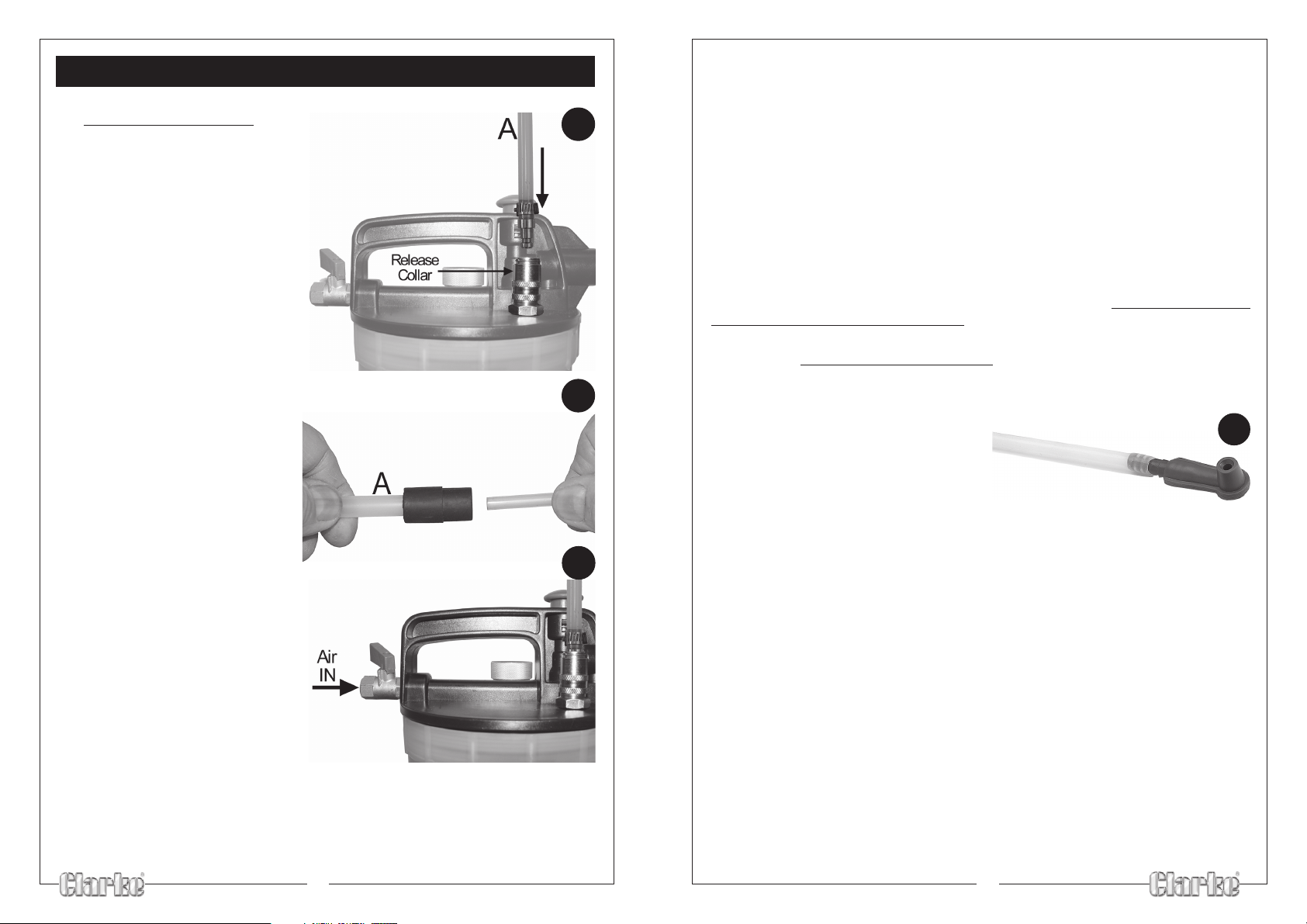
• Connect the hard extraction
hose (A), which is provided with
a quick release male coupling,
to the fluid inlet connector, as
indicated - Fig.1. Simply push it
in until it clicks into place. To
remove it, push down on the
release collar and it will spring
out on its own accord.
• Connect the other end of
the hard extraction hose (A)
to the thinner extraction tube,
via the connector provided.
• Connect the compressor hose to
the air inlet connector, ensuring
the tap is turned to the OFF
position i.e. across the line of air
flow.
1
2
3
• Slowly open the air inlet tap on the fluid extractor.
• Press the button, on top of the unit, down.
Air will now flow through the unit and oil will begin to be sucked out, and into the
container.
NOTE: It may be necessary to increase air pressure being delivered in order to
extract oil effectively, by adjusting the regulator on the compressor. NEVER exceed
12bar. (170psi).
As the level of the fluid in the container rises, afloat will rise with it. This will eventually
cut off the air supply, thereby stopping the extraction process.
At this point, shut off the air supply, and pull off the drain cap, on top of the unit it is held in place by an O-Ring, and may be difficult to pry off initially, but ‘wiggling’
it from side to side will have the desired effect.
Drain the oil into a suitable receptacle, remembering to dispose of waste oil
according to all waste oil regulations.
B. Extracting Brake Fluid
The process is similar to that for extracting engine oil, except that a soft hose with
a special adapter is used in place of the hard extraction hose and thinner extraction
tube. The adapter is shown in Fig. 5.
• Thoroughly clean around the Brake
Fluid reservoir filler cap, before
removing it and putting it safely to one
side.
• Attach the soft rubber hose, with the quick-fit male connector
attached, to the fluid intlet connector.
• Using a suitable ring spanner, slacken off the bleed nipple of the wheel cylinder
furthest from the brake fluid reservoir, sufficient for the fluid to flow, then simply
place the adapter on the bleed nipple, and hold it in this position - firmly.
• Start the air compressor according to the manufacturers instructions, and adjust
the output pressure to approx. 5bar.
• Slowly open the air inlet tap on the fluid extractor, press the button, on top of
the unit, down and proceed to extract the fluid in the system.
NOTE: As fluid is extracted, the oil level in the reservoir will lower. It is vital however
that the level is maintained to prevent air entering the system. Either extract small
quantities in order to top up the reservoir regularly, or, preferably, get an assistant
to maintain the level, by topping up using a suitable clean funnel.
5
• With the engine oil warm, and the vehicle on a flat level surface, remove the
dipstick, then insert the end of the small diameter tube into the dipstick hole
far enough so that the end rests at the bottom of the sump.
• Start the air compressor according to the manufacturers instructions, and adjust
the output pressure to approx. 5bar.
4
• When clean oil is seen to be extracted, tighten the bleed nipple.
NOTE: Due to the way in which fluid is extracted, some air will always be sucked in
with the fluid, it should not be assumed therefore that the fluid within the system
contains air.
• Repeat the procedure at the remaining wheel cylinders.
5
 Loading...