

Page 1
HAND TOOLS
Brake Bleeder Kit
Brake Bleeder Kit
MODEL NO: CHT 470
PART No: 1801470
OPERATION & MAINTENANCE
INSTRUCTIONS
0603
Page 2
Thank you for purchasing this CLARKE Pneumatic Fluid Extractor, which is designed for general
use in garages and workshops etc.
Before attempting to use the tool, please read this manual thoroughly and follow the
instructions carefully. In doing so you will ensure the safety of yourself and that of others
around you, and you can look forward to the extractor giving you long and satisfactory
service.
CLARKE GUARANTEE
This CLARKE product is guaranteed against faulty manufacture for a period
of 12 months from the date of purchase. Please keep your receipt as proof
of purchase.
This guarantee is invalid if the product is found to have been abused or
tampered with in any way, or not used for the purpose for which it was
intended.
Faulty goods should be returned to their place of purchase, no product
can be returned to us without prior permission.
This guarantee does not effect your statutory rights.
Specifications
Maximum Fluid Capacity In Tank................................ 2000ml
Maximum Fluid Capacity In Refill Bottle ..................... 1000ml
Working Air Pressure ...................................................... 70 - 170 PSI
A verage Air Consumption ........................................... 4.5 cfm
Air Inlet ............................................................................ ¼BSP
Net Weight ..................................................................... kg
Maximum Operating Temperature ............................ 60ºc
WARNING
Compressed air can be
dangerous. Ensure that you are
thoroughly familiar with all
precautions relating to the use
of compressors and
compressed air supply.
Please note that the details and specifications contained herein, are correct at the time of going to print. However,
CLARKE International reserve the right to change specifications at any time without prior notice.
-1- -6-
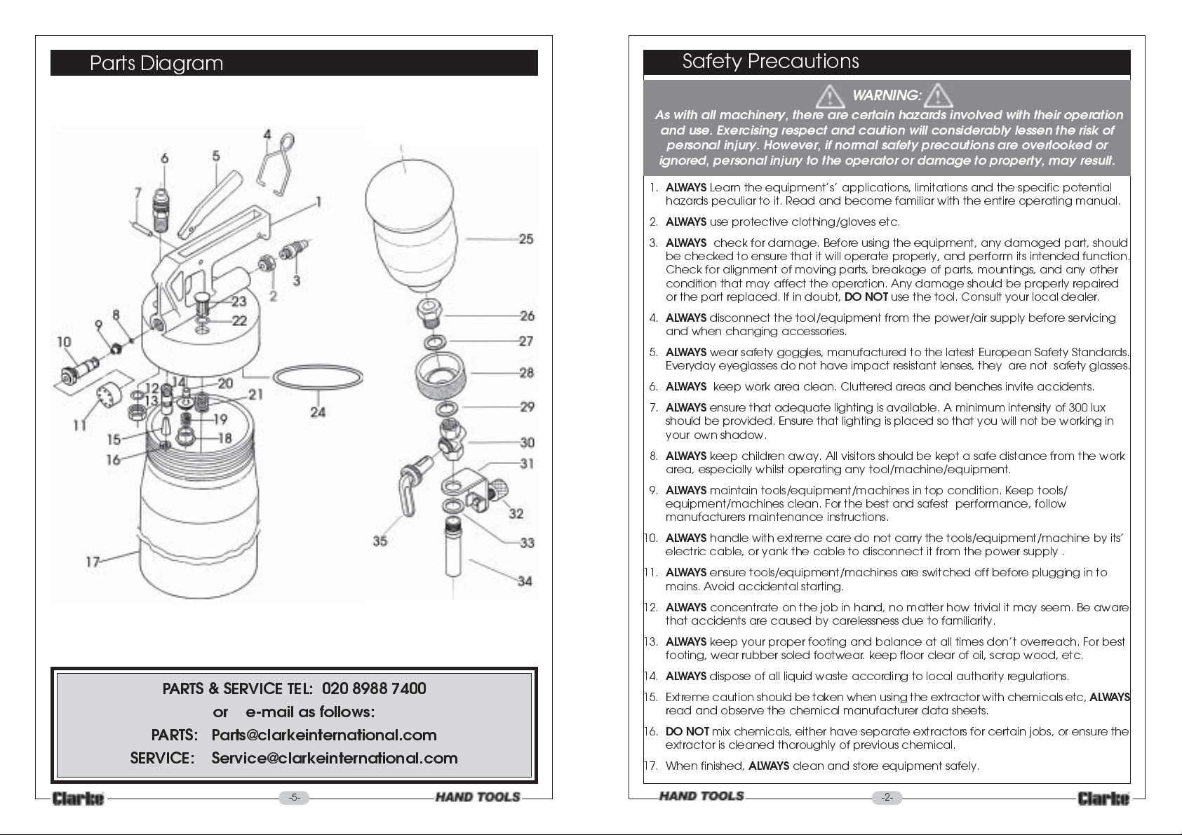
Parts List
Index No Part No Description Qty
1 2113-1 Cover Housing 1
2 2113-2 Inlet Nut 1
3 2113-3 Air Inlet Coupler 1
4 2113-4 Trigger Retainer 1
5 2113-5 Trigger 1
6 2113-6 Fluid Inlet Coupler 1
7 2113-7 Pin 1
8 2113-8 O Ring 1
9 2113-9 Vacuum Valve 1
10 2113-10 Vacuum Body 1
11 2113-11 Silencer 1
12 2113-12 O Ring 1
13 2113-13 Lock Nut 1
14 2113-14 Safety Valve 1
15 2113-15 Safety Cap 1
16 2113-16 C Clip 1
17 2113-17 Tank 1
18 2113-18 Locking Screw 1
19 2113-19 Spring 1
20 2113-20 Valve 1
21 2113-21 Spring 1
22 2113-22 O Ring 1
23 2113-23 Safety Valve 1
24 2113-24 Seal 1
25 2113-25 Bottle 1
26 2113-26 Connector 1
27 2113-27 Washer 1
28 2113-28 Swivel Clamp Assy 1
32 2113-32 Knurled Screw 1
32a 2113-32a Grip 1
32b 2113-32b C Clip 1
33 2113-33 washer 1
34 2113-34 Fluid Outlet Tube 1
35 2113-35 Tap 1
35a 2113-35a Tap Seal 1
36 2113-36 1 Metre Silicon Hose (Not Shown) 1
37 2113-37 Plastic Connector (Not Shown) 1
38 2113-38 Nipple Adapter (Not Shown) 1
Page 3
Parts Diagram
PARTS & SERVICE TEL: 020 8988 7400
or e-mail as follows:
PARTS: Parts@clarkeinternational.com
SERVICE: Service@clarkeinternational.com
Safety Precautions
WARNING:
As with all machinery, there are certain hazards involved with their operation
and use. Exercising respect and caution will considerably lessen the risk of
personal injury. However, if normal safety precautions are overlooked or
ignored, personal injury to the operator or damage to property, may result.
1.
AL WAYS
hazards peculiar to it. Read and become familiar with the entire operating manual.
2.
AL WAYS
3.
AL WA YS
be checked to ensure that it will operate properly, and perform its intended function.
Check for alignment of moving parts, breakage of parts, mountings, and any other
condition that may affect the operation. Any damage should be properly repaired
or the part replaced. If in doubt,
4.
AL WAYS
and when changing accessories.
5.
ALWAYS
Everyday eyeglasses do not have impact resistant lenses, they are not safety glasses.
6.
AL WA YS
7.
ALWAYS
should be provided. Ensure that lighting is placed so that you will not be working in
your own shadow.
8.
ALWAYS
area, especially whilst operating any tool/machine/equipment.
9.
AL WAYS
equipment/machines clean. For the best and safest performance, follow
manufacturers maintenance instructions.
10.
AL WAYS
electric cable, or yank the cable to disconnect it from the power supply .
11.
AL WAYS
mains. Avoid accidental starting.
12.
ALWAYS
that accidents are caused by carelessness due to familiarity.
13.
AL WAYS
footing, wear rubber soled footwear. keep floor clear of oil, scrap wood, etc.
14.
ALWAYS
15. Extreme caution should be taken when using the extractor with chemicals etc,
read and observe the chemical manufacturer data sheets.
16.
DO NOT
extractor is cleaned thoroughly of previous chemical.
17. When finished,
Learn the equipments applications, limitations and the specific potential
use protective clothing/gloves etc.
check for damage. Before using the equipment, any damaged part, should
DO NOT
disconnect the tool/equipment from the power/air supply before servicing
wear safety goggles, manufactured to the latest European Safety Standards.
keep work area clean. Cluttered areas and benches invite accidents.
ensure that adequate lighting is available. A minimum intensity of 300 lux
keep children away. All visitors should be kept a safe distance from the work
maintain tools/equipment/machines in top condition. Keep tools/
handle with extreme care do not carry the tools/equipment/machine by its
ensure tools/equipment/machines are switched off before plugging in to
concentrate on the job in hand, no matter how trivial it may seem. Be aware
keep your proper footing and balance at all times dont overreach. For best
dispose of all liquid waste according to local authority regulations.
mix chemicals, either have separate extractors for certain jobs, or ensure the
ALWAYS
clean and store equipment safely.
use the tool. Consult your local dealer.
ALWAYS
-5- -2-
Page 4
CC
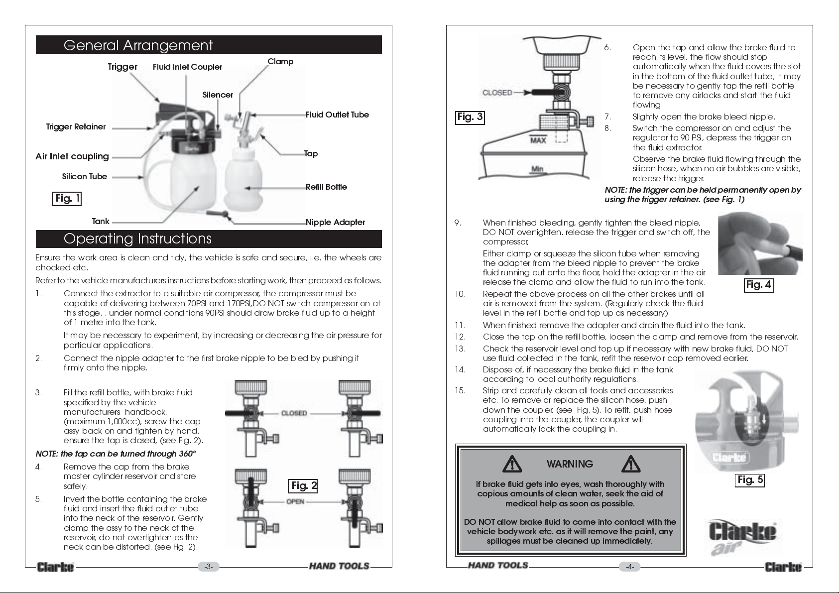
General Arrangement
Trigger
Trigger Retainer
Air Inlet coupling
Silicon Tube
Fig. 1
Fluid Inlet Coupler
Silencer
Clamp
Fluid Outlet Tube
Tap
Refill Bottle
Fig. 3
6. Open the tap and allow the brake fluid to
reach its level, the flow should stop
automatically when the fluid covers the slot
in the bottom of the fluid outlet tube, it may
be necessary to gently tap the refill bottle
to remove any airlocks and start the fluid
flowing.
7. Slightly open the brake bleed nipple.
8. Switch the compressor on and adjust the
regulator to 90 PSI, depress the trigger on
the fluid extractor.
Observe the brake fluid flowing through the
silicon hose, when no air bubbles are visible,
release the trigger.
NOTE: the trigger can be held permanently open by
using the trigger retainer. (see Fig. 1)
Tank
Nipple Adapter
Operating Instructions
Ensure the work area is clean and tidy, the vehicle is safe and secure, i.e. the wheels are
chocked etc.
Refer to the vehicle manufacturers instructions before starting work, then proceed as follows.
1. Connect the extractor to a suitable air compressor, the compressor must be
capable of delivering between 70PSI and 170PSI,DO NOT switch compressor on at
this stage. . under normal conditions 90PSI should draw brake fluid up to a height
of 1 metre into the tank.
It may be necessary to experiment, by increasing or decreasing the air pressure for
particular applications.
2. Connect the nipple adapter to the first brake nipple to be bled by pushing it
firmly onto the nipple.
3. Fill the refill bottle, with brake fluid
specified by the vehicle
manufacturers handbook,
(maximum 1,000cc), screw the cap
assy back on and tighten by hand.
ensure the tap is closed, (see Fig. 2).
NOTE: the tap can be turned through 360º
4. Remove the cap from the brake
master cylinder reservoir and store
safely.
5. Invert the bottle containing the brake
fluid and insert the fluid outlet tube
into the neck of the reservoir. Gently
clamp the assy to the neck of the
reservoir , do not overtighten as the
neck can be distorted. (see Fig. 2).
Fig. 2
9. When finished bleeding, gently tighten the bleed nipple,
DO NOT overtighten. release the trigger and switch off, the
compressor ,
Either clamp or squeeze the silicon tube when removing
the adapter from the bleed nipple to prevent the brake
fluid running out onto the floor, hold the adapter in the air
release the clamp and allow the fluid to run into the tank.
10. Repeat the above process on all the other brakes until all
air is removed from the system. (Regularly check the fluid
level in the refill bottle and top up as necessary).
11. When finished remove the adapter and drain the fluid into the tank.
12. Close the tap on the refill bottle, loosen the clamp and remove from the reservoir.
13. Check the reservoir level and top up if necessary with new brake fluid, DO NOT
use fluid collected in the tank, refit the reservoir cap removed earlier.
14. Dispose of, if necessary the brake fluid in the tank
according to local authority regulations.
15. Strip and carefully clean all tools and accessories
etc. To remove or replace the silicon hose, push
down the coupler, (see Fig. 5). To refit, push hose
coupling into the coupler, the coupler will
automatically lock the coupling in.
Fig. 4
WARNING
If brake fluid gets into eyes, wash thoroughly with
copious amounts of clean water, seek the aid of
medical help as soon as possible.
DO NOT allow brake fluid to come into contact with the
vehicle bodywork etc. as it will remove the paint, any
spillages must be cleaned up immediately.
Fig. 5
-4--3-
 Loading...