

Page 1
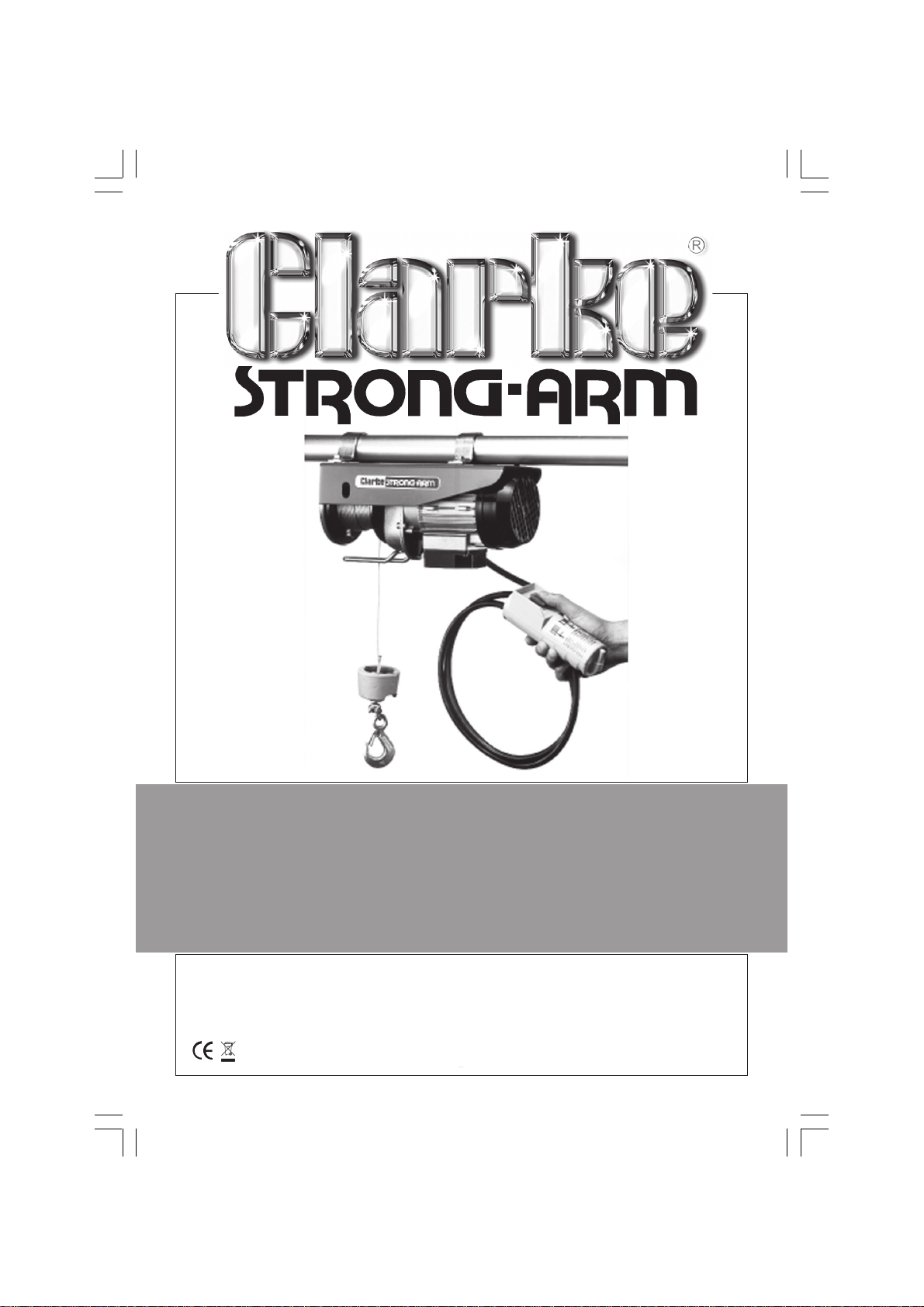
250kg and 400kg
250kg and 400kg
POWER WINCH
POWER WINCH
Models CHP 250 and CHP 400
Part Nos. 7630400 and 7630420
OPERATING & MAINTENANCE
INSTRUCTIONS
0607
Page 2
Thank you for purchasing this CLARKE Power Winch.
This versatile machine is designed for domestic, non-industrial use, and is ideal for
winching trailers, raising straw bales etc.
Before operating the machine, please read this leaflet thoroughly and follow the
instructions carefully. In doing so you will ensure the safety of yourself and that of
others around you, and you can look forward to the Power Winch giving you long
and satisfactory service.
GUARANTEE
This CLARKE product is guaranteed against faulty manufacture for a period of 12 months
from the date of purchase. Please keep your receipt as proof of purchase. This guarantee
is invalid if the product is found to have been abused or tampered with in any way, or not
used for the purpose for which it was intended.
Faulty goods should be returned to their place of purchase, no product can be returned
to us without prior permission. This guarantee does not effect your statutory rights.
SAFETY PRECAUTIONS
1. This machine is designed for indoor, domestic use. Do not use outdoors unless
it is completely protected against the elements.
2. Keep children well away from the machine.
3. Do not service the machine in any way when it is plugged in to an electrical supply.
4. Protect the machine from extreme weather conditions, i.e. frost and/or high
temperatures.
5. The machine is not equipped with an overload cut-out. If the load exceeds
the capacity of the machine, do not persist in pushing the hoist button as this
will cause the motor to overheat and eventually damage will be inccurred.
6. NEVER stand beneath a raised load.
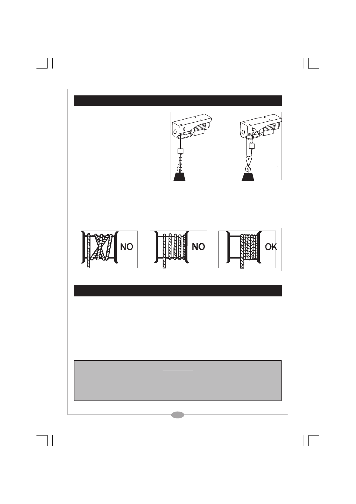
7. Before operating it is important to ensure that the steel cable is correctly wound
around the drum - see fig. 3, page 4.
8. Before operating ensure that at least THREE turns of the cable are wound
around the drum.
9. If the cable needs replacing, ensure it is replaced with one of identical
specification. Contact your CLARKE dealer or the CLARKE International Service
Department for advice.
10. Ensure that the switches are kept in good condition.
11. Before use, always inspect the machine and its’ mountings to ensure they are
in good condition. If any damaged or broken parts are found, the machine should
be removed from service and the parts renewed or repaired before further use.
12. Always wear industrial gloves when operating the machine.
13. When pulling or dragging a horizontal load, do not stand between the load
and the machine and keep others well away from the area.
2
Page 3
ELECTRICAL CONNECTIONS
Connect the mains lead to a standard, 230 Volt (50Hz) electrical supply through an
approved 13 amp BS 1363 plug, or a suitably fused isolator switch.
WARNING! THIS APPLIANCE MUST BE EARTHED
IMPORTANT: The wires in the mains lead are coloured in accordance with the following
code: Green & Yellow - Earth
Blue - Neutral
Brown - Live
As the colours of the flexible cord of this appliance may not correspond with the coloured
markings identifying terminals in your plug proceed as follows:
Connect GREEN & YELLOW coloured cord to plug terminal marked with a letter “E”
or Earth symbol “ ” or coloured GREEN or GREEN & YELLOW.
Connect BROWN cord to plug terminal marked with a letter “L” or coloured RED.
Connect BLUE cord to plug terminal marked with a letter “N” or coloured BLACK.
If this appliance is fitted with a plug which is moulded onto the electric cable (i.e. nonrewirable) please note:
1. The plug must be thrown away if it is cut from the electric cable. There is a danger of
electric shock if it is subsequently inserted into a socket outlet.
2. Never use the plug without the fuse
cover fitted.
3. Should you wish to replace a detachable fuse carrier, ensure that the
correct replacement is used (as
indicated by marking or colour
code).
4. Replacement fuse covers can
be obtained from your local
dealer or most electrical stockists.
5. The fuse in the plug must be replaced with one of the same rating (13 amps) and
this replacement must be ASTA approved to BS1362
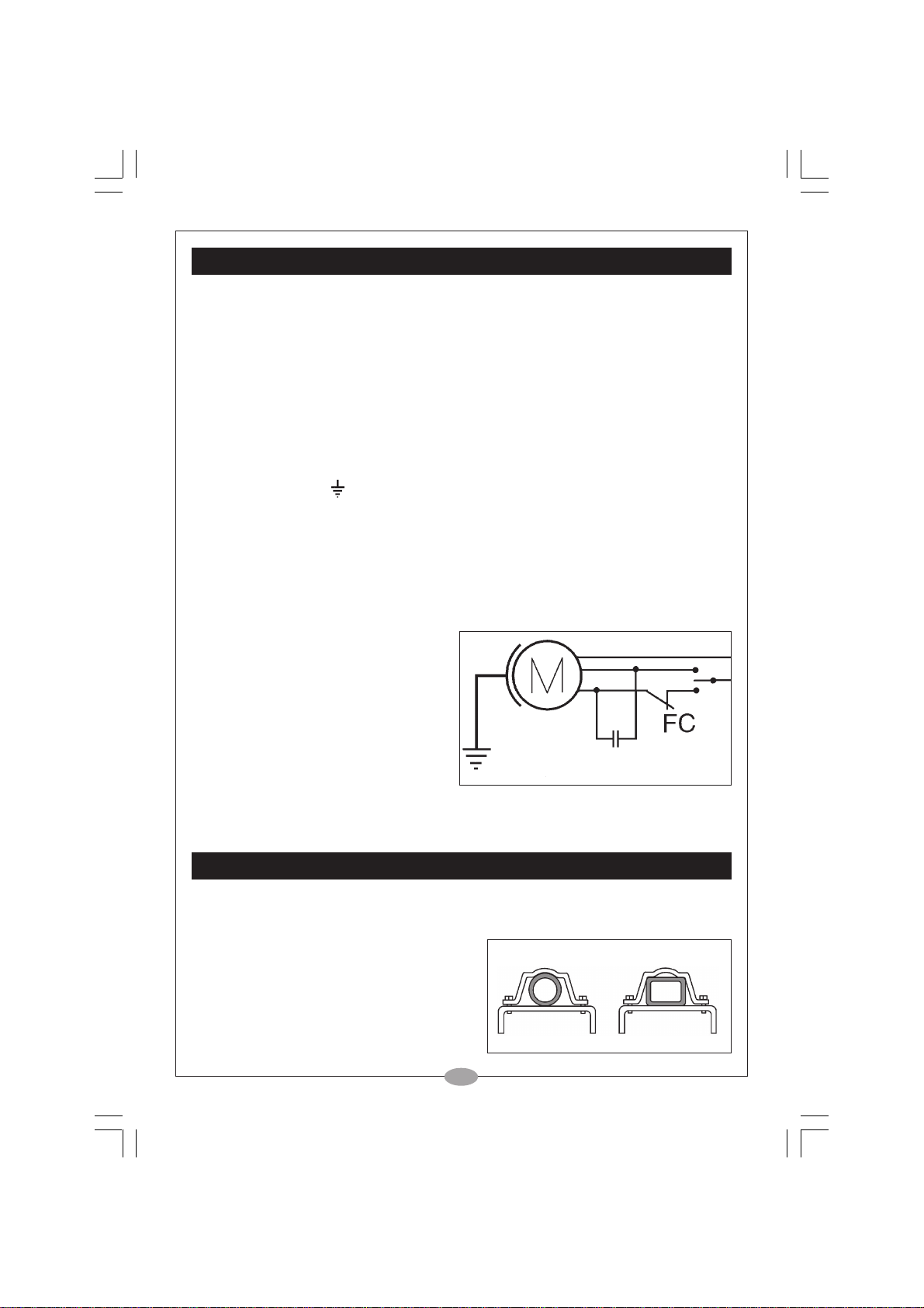
Wiring Diagram
INSTALLATION
The Hoist is provided with a specially designed brackets allowing it to be attached to
pipes, box sections or rectangular beams. (see fig. 1)
Beam dimensions must be carefully
calculated and all mountings must be of
adequate size and capable of sustaining the
maximum load of the hoist, plus the weight of
the hoist and mountings.
If there is any uncertainty. You should consult
a qualified engineer.
3
Fig.1
Page 4
OPERATION
Taking all necessary precautions
previously stated, pay out the cable,
under tension so that the coils on the
drum remain neatly in place. Attach
the hook to the load, ensuring it is
directly above the centre of gravity of
the load, or in a direct line with the
winch.
Ensuring that no obstacle prevents a
clean lift or pull, gently raise the load
or winch ‘in’.
When lowering a load, be aware that when the hoist button is released, the load will not
stop immediately, but may continue for a few more millimeters as the brake takes effect
It is possible to double the capacity of the hoist by doubling the cable about the pulley,
and attaching the hook to the hoist casing via the hole provided.(see fig. 2)
Fig. 2.
Fig.3.
MAINTENANCE
Before use, check to ensure the motor stop switch and push button switch are in good
condition.
Periodically, fully unwind the cable and check its general condition, for fraying, corrosion
etc.
Periodically check the security and condition of the mountings and brackets.
Periodically check the tightness of all bolts and screws.
NOTE: When in constant use, the hoist should be inspected more frequently - at least
monthly.
IMPORTANT
These machines have been tested to a safety factor of 1.25.
Following repairs or disassembly, they must be re-tested with a static load of
315kg (CHP250) or 500kg (CHP400), in double wire mode.
There must be no failure or deformity of any kind incurred.
4
Page 5
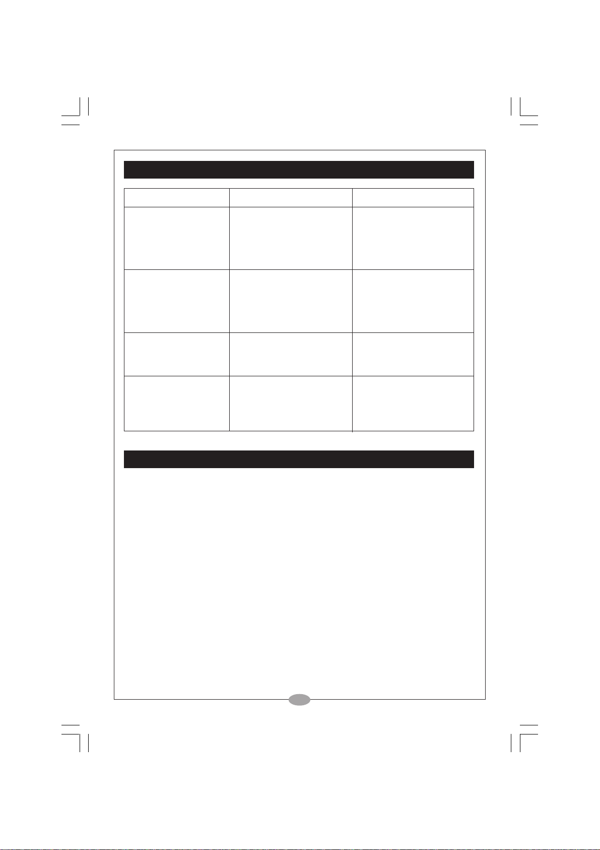
TROUBLESHOOTING
PROBLEM CAUSES REMEDIES
When operating the
switch the motor does
not run.
1. The cable or extension
is not plugged in
correctly
2. Power failure
1. Plug in the power cable
2. Check plug fuse, and
correctly
ensure outlet is live.
Motor hums but will not
hoist
Brake does not operate,
and load slips
Cable twisted frayed or
kinked
1. The motor has overheated
2. The load exceeds the
hoist capacity
3. Brake has become stuck
during storage.
1. Brake is worn out
1. Incorrectly wound on
drum.
2. Cable stored unwound,
in poor conditions.
1. Allow it to cool down
2. Reduce the load
3. Press hoist button quickly
a few times to free brake
1. Renew brake
Contact your CLARKE
dealer for advice
1. Replace cable.
2. Replace cable.
SPECIFICATIONS
CHP250 CHP 400
Load Capacity (Single Cable) 125kg 200kg
Lifting Height (Single Cable) 11m 12m
Load Capacity (Double Cable) 250 kg 400kg (Double Cable)
Lifting Height (Double Cable) 5.5 m 6m
Lifting Speed (Single Cable) 5.5 m/min 6 m/min
Cable Length 12 m 13m
Cable Diameter 3mm Twist Free 3.6mm Twist Free
Resister cable 900 kg 1400kg
Duty Cycle S3 25% 4min S3 40% 4 min
Electrical Supply 230V 50 Hz 1 Phase 230V 50 Hz 1 Phase
Power rating 530 Watts 880 Watts
Dimensions 366x155x230 mm 400x170x260 mm
Noise Level > 70dB at 125kg load > 70dB at 200kg load
Weight 10 kg 16kg
5
Page 6
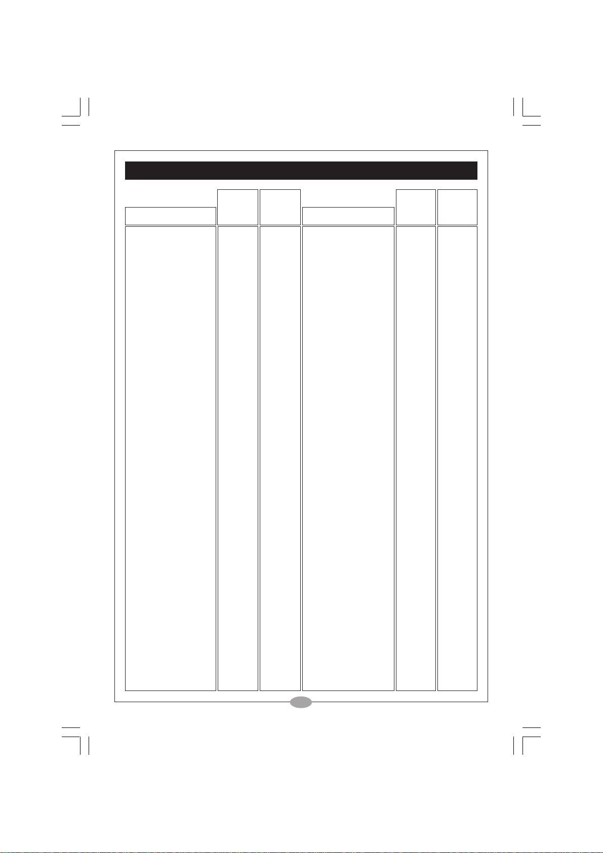
PARTS LIST
CHP250 CHP400 CHP250 CHP400
No.Description Part No. Part No. No. Description Part No. Part No.
1 Fan Cover 502002 502006 30 Screw 401012 401011
2 Fan 502001 502005 31 Safety Ring 84 84
3 Shield 100 150 32 Clamp 510005 510002
4 Casing w/Stator 634002 634003 33 U Bolt 510007 510007
5 Stud 409001 409006 34 Hook 515002 515002
6 Bearing 440001 440006 35 Bearing 440003 440003
7 Gasket Friction n/a n/a 36 Pinion 115 162
8 Hub 35004 35004 37 Key 428003 428003
9 Hub Gasket 350004 350005 38 Connector 425002 425002
10 Spring 512001 512003 39 Switch 302002 302002
11 Shaft 101A 151 40 Spring 512002 512002
12 Bearing 440001 440006 41 Cable Electric n/a n/a
13 Flange 107 157 42 Cover 610004 610004
14 Gasket 135 135 43 Switch 610005 610005
15 Circlip 424001 424001 44 Screw 410002 410002
16 Pinion 154 161 45 Grip 113 163
17 Bearing 440002 440002 46 Capacitor 615004 615006
18 Housing 159 159 47 Grip 108 158
19 Support Hsg. 85 175 48 Screw 411001 411001
20 Washer 420002 420002 49 Screw 410003 410003
21 Screw 401003 401003 50 Cable 616002 616002
22 Screw 406001 406001 51 Clamp 522002 522002
23 Bracket 131 131 52 Gasket n/a n/a
24 Key 428002 428002 53 Terminal 502007 502007
25 Shaft 110 160 54 Grommet 523005 523005
26 Drum 74 166 55 Cable Electric 614003 614001
27 Cable 125x12 350001 350006 56 Cable Electric 616007 616007
27 Cable 125x15 350002 350007 57 Grommet 523008 503008
27 Cable 125x6 350003 350008 58 Clip 523001 523001
28 Bush 128 128 59 Cable 616003 616003
29 Cable Ring 119 169 60 Pinion 154 154
61 Pulley/Hook Assy n/a n/a
6
Page 7
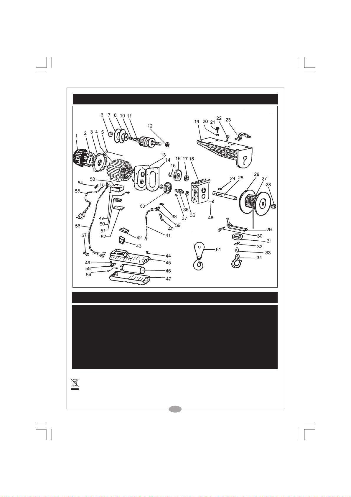
PARTS DIAGRAM
PARTS & SERVICE CONTACTS
For Spare Parts and Service, please contact your nearest dealer,
or CLARKE International, on one of the following numbers.
PARTS & SERVICE TEL: 020 8988 7400
PARTS & SERVICE FAX: 020 8558 3622
or e-mail as follows:
PARTS: [email protected]
SERVICE: [email protected]
When disposing of this product, do not dispose of with general waste. It must be disposed of according to the laws
governing Waste Electrical and Electronic equipment, at a recognised disposal facility.
Please note that the details and specifications contained herein, are correct at the time of going to print. However, CLARKE
International reserve the right to change specifications at any time without prior notice.
7
Page 8

 Loading...