

Page 1
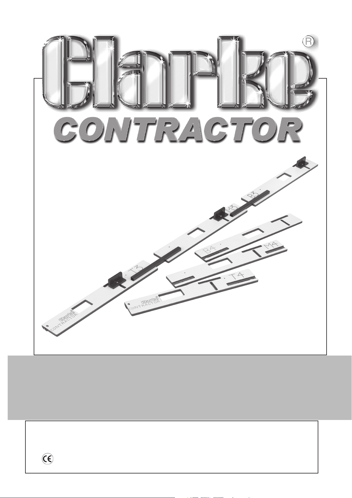
HINGE JIG
HINGE JIG
Model No: CHJ110
Part No: 6462121
OPERATION & MAINTENANCE
INSTRUCTIONS
0405
Page 2

Please note that the details and specifications contained herein, are correct at the time of going
to print. However, CLARKE International reserve the right to change specifications at any time
without prior notice.
-1-
Page 3
Thank you for purchasing this CLARKE Hinge Jig Set
Before attempting to use the jig, please read this manual thoroughly and follow the
instructions carefully. In doing so you will ensure the safety of yourself and that of others
around you, and you can look forward to the jig set giving you long and satisfactory
service.
CLARKE GUARANTEE
This CLARKE product is guaranteed against faulty manufacture for a period of 12
months from the date of purchase. Please keep your receipt as proof of purchase.
This guarantee is invalid if the product is found to have been abused or tampered
with in any way, or not used for the purpose for which it was intended.
Faulty goods should be returned to their place of purchase, no product can be
returned to us without prior permission.
This guarantee does not effect your statutory rights.
Introduction
An easy to use and carry high quality hinge jig for precision fitting of 3” and 4” hinges.
Assembly and setting time is minimal, can be quickly dismantled for storage.
Specifications
Hinge Length.......................................... 3” & 4”
Hinge Width............................................ Min. 3/8” (9mm) Max. 1 1/2” (38mm)
Door Height ............................................ Min. 6’5” (1955mm) Max. 6’8” (2032mm)
Contents
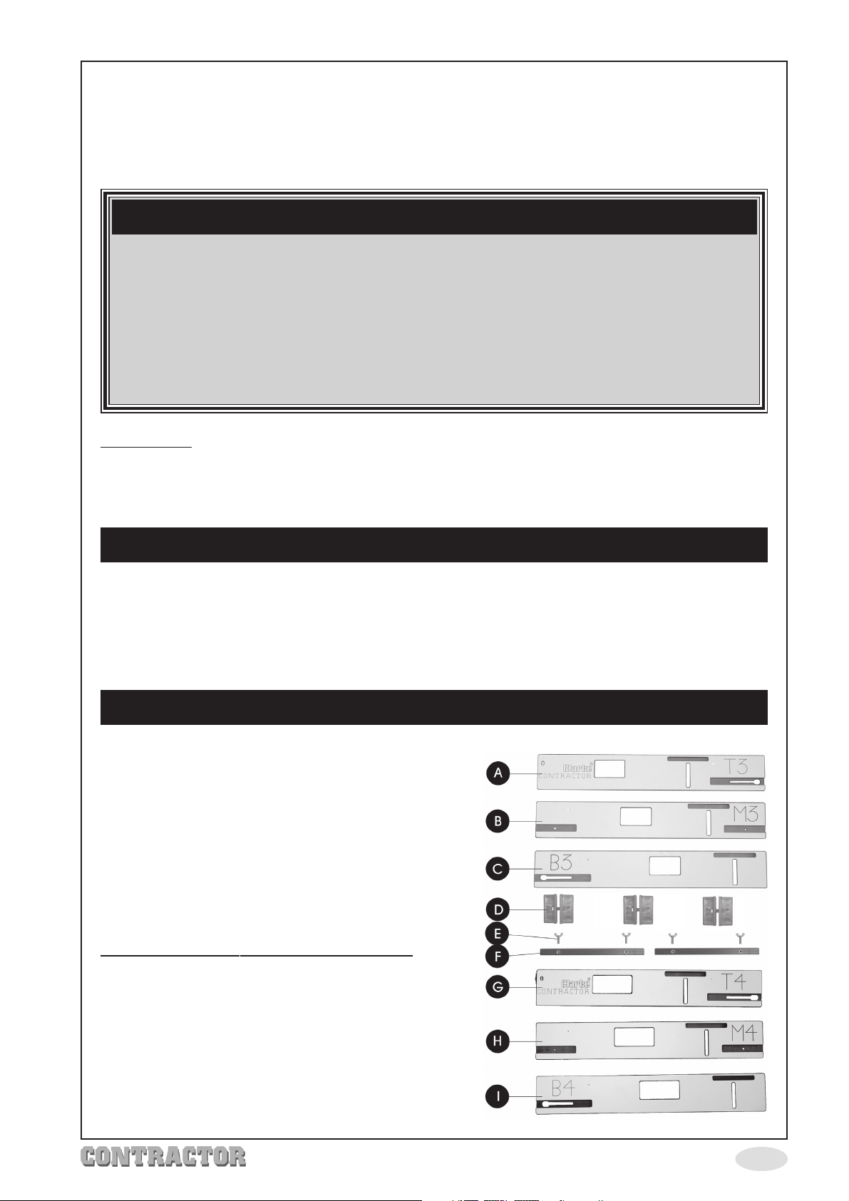
3 X 3” hinge jig plates : T3 (top plate ‘A’), M3
(middle plate ’B’) & B3 (bottom plate ‘C’).
3 X 4” hinge jig plates: T4 (top plate ’G’), M4
(middle plate ‘H’) & B4 (bottom plate ‘I’).
3 aligning/clamping sets (D).
2 adjustable connecting bars (F).
4 wing screws (E).
1 instruction Manual.
Other equipment required (not supplied).
Light duty plunge router capable of taking a
16mm guide bush.
16mm guide bush.
12.7mm (½”) router bit.
Minimum of 3 ‘G’ clamps or similar.
Folding workbench.
-2-
Page 4
Safety Precautions
WARNING:
As with all machinery, there are certain hazards involved with their operation and
use. Exercising respect and caution will considerably reduce the risk of personal
injury. However, if normal safety precautions are overlooked or ignored, personal
injury to the operator or damage to property, may result.
1. ALWAYS Learn the equipments applications, limitations and any
specific potential hazards peculiar to it. Read and become familiar
with the entire operating manual.
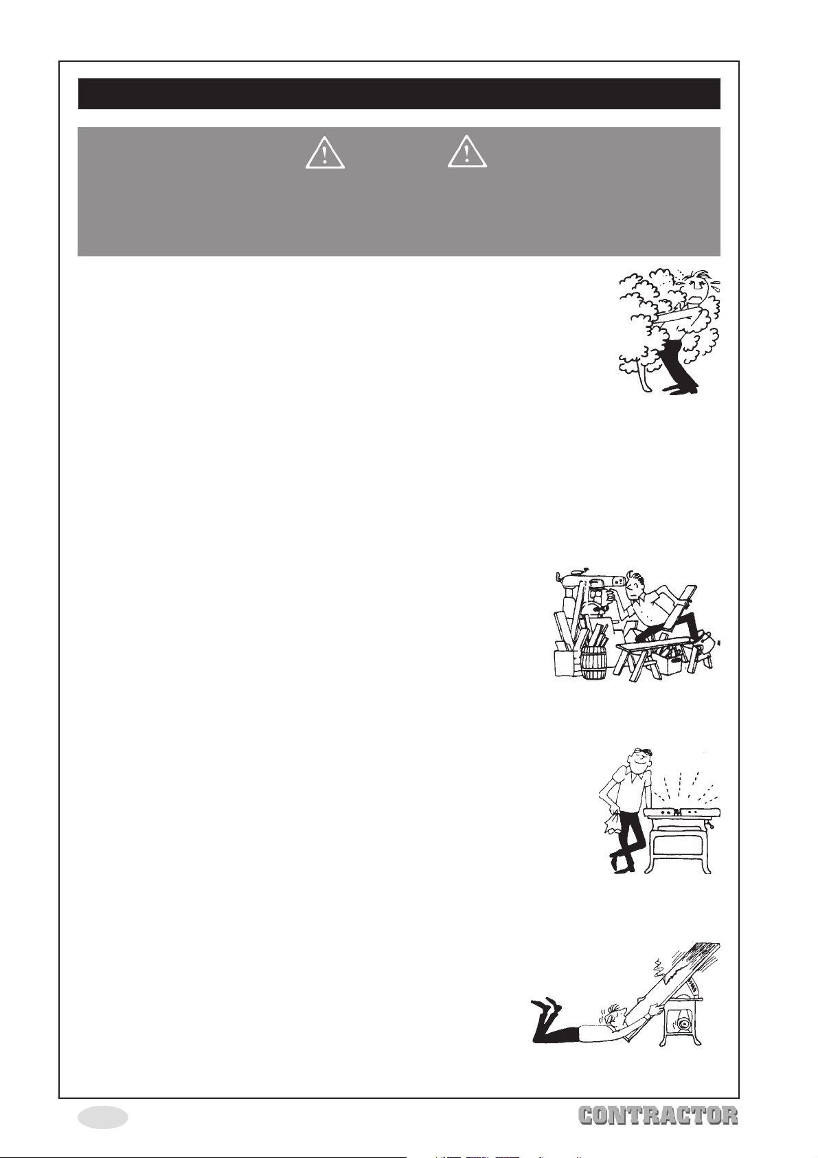
2. ALWAYS use a face or dust mask if operation is particularly dusty.
3. ALWAYS check for damage. Before using tools and equipment, any
damage should be checked to ensure that it will operate properly,
and perform its intended function. Check for alignment of moving
parts, breakage of parts, mountings, and any other condition that may affect the
equipments operation. Any damage should be properly repaired or the part replaced.
If in doubt, DO NOT use. Consult expert advice.
4. ALWAYS disconnect power tools from the electric supply before servicing and when
making adjustments or changing accessories etc.
5. ALWAYS wear safety goggles, manufactured to the latest European Safety Standards.
Everyday eyeglasses do not have impact resistant lenses, they are not safety glasses.
6. ALWAYS keep work area clean. Cluttered areas and benches
invite accidents.
7. ALWAYS ensure that adequate lighting is available. A
minimum intensity of 300 lux should be provided. Ensure that
lighting is placed so that you will not be working in your own
shadow.
8. ALWAYS keep children away. All visitors should be kept a safe distance from the work
area, especially whilst working with tools, particularly power tools.
9. ALWAYS maintain equipment in top condition. Keep tools/machines
clean for the best and safest performance. Follow maintenance
instructions.
10. ALWAYS handle with extreme care do not carry tools/machines by
the electric cable, or yank the cable to disconnect it from the
power supply.
11. ALWAYS ensure the switch is off before plugging in to mains. Avoid
accidental starting.
12. ALWAYS concentrate on the job in hand, no matter how trivial it may seem. Be aware
that accidents are caused by carelessness due to familiarity.
13. ALWAYS keep your proper footing and balance at all times
don’t overreach. For best footing, wear rubber soled
footwear. Keep floor clear of oil, scrap wood etc.
14. ALWAYS seek assistance when lifting heavy objects
(worktops etc.).
-3-
Page 5
Operation
Before commencing:
ALWAYS ensure the work area is safe and secure.
ALWAYS ensure the door is supported properly, ideally using a folding workbench or similar.
ALWAYS ensure the router path is clear of any obstacles etc.
ALWAYS ensure the router power cable is clear of the jig and is of sufficient length.
ALWAYS read and understand the router instruction manual to ensure safe operation.
Jig Assembly
Select the plates required either 3” or 4”.
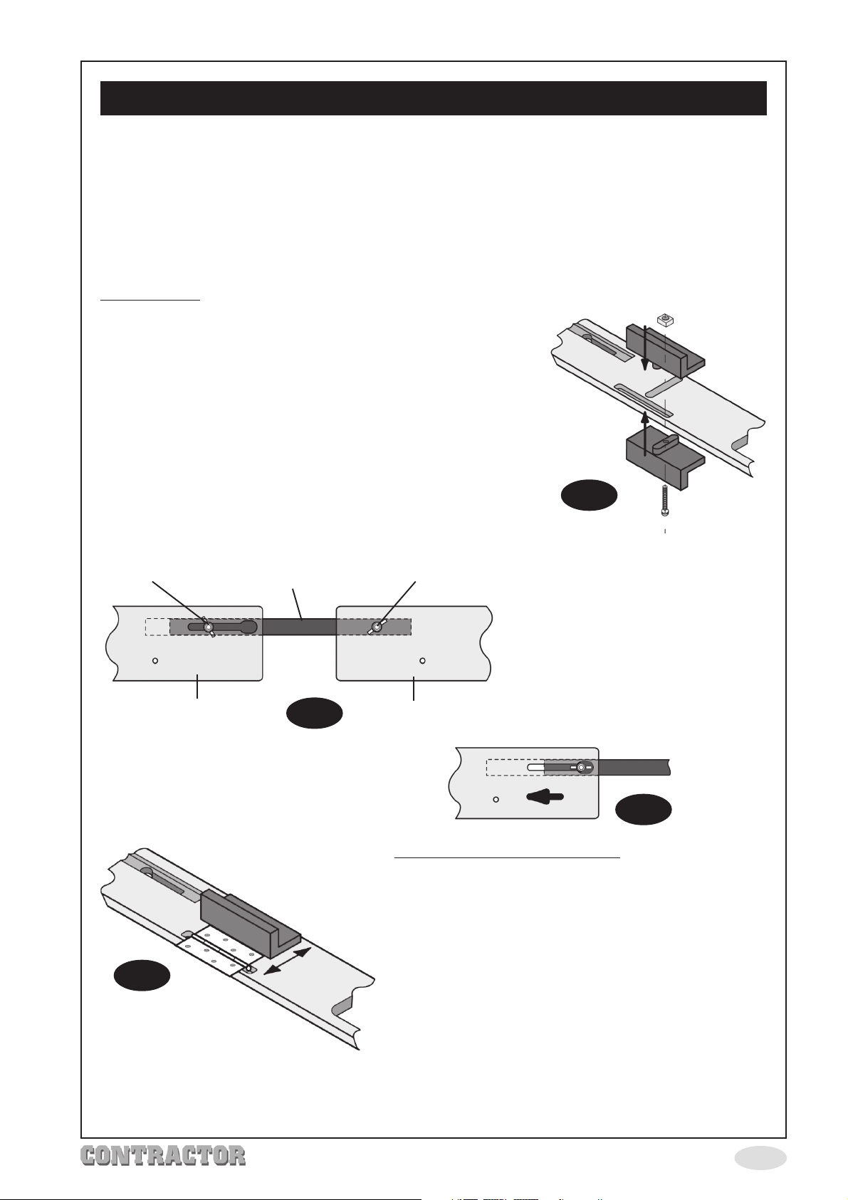
Attach the aligning/clamping sets using nuts and screws
supplied (Fig. 1), ensure the square nut sits in the recess,
DO NOT fully tighten screws, leave loose enough to allow
the clamping sets to slide backwards and forwards for
adjustment later.
Join plates using the adjustable connecting bars.
Attach both bars to the middle plate first and firmly secure
with wing screws (Fig. 2).
Attach top and bottom plates leaving wing screws loose
to enable adjustment
Fig. 1
Wing Screw Wing Screw
Top/Bottom Plate Middle Plate
Fig. 4
Connecting Bar
Fig. 2
Setting Width Of Hinge Recess
1. Slide the alignment/clamping block to the back
of the plate.
2. Position the knuckle of the hinge in the slot
opposite the alignment/clamping block as in
Fig. 4.
3. Push the alignment/clamping block against the
edge of the hinge as in Fig. 4.
NOTE: ONLY the Top and Bottom
plates are adjustable, and can be
easily removed from assembly by
simply loosening the wing screw
and sliding the plate in direction
of arrow (Fig. 3) this allows the wing
screw to pass through keyhole.
Fig. 3
4. Tighten the alignment/clamping block securing
screw.
5. Repeat steps, 1,2,3 &4 for the remaining
alignment/clamping sets.
-4-
Page 6
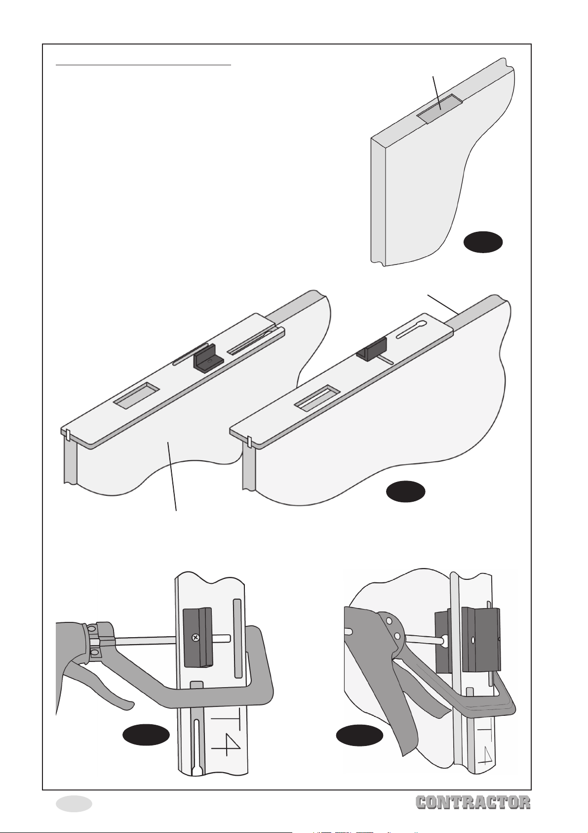
Positioning And Adjusting The Jig.
1. Separate the 3 sections by loosening the wing screws
in the top and bottom plates, slide each plate so that
the wing screw passes through the keyhole.
2. Place the top plate on the edge of the door so that
the clamping block is set against the open face of
the door.
Note: The open face of the door is the side
where the hinge is fitted, (see fig. 5).
3. Loosen the end swivel securing screw on the top plate
and turn the swivel through 90º so that the top plate is
flush with the top of the door, (see Fig. 6). This will set
the aperture for the top hinge 6” from the top of the
door.
Hinge Recess
Open Face
NOTE: the hinge plates can be positioned upside down
so that the connecting bars sit underneath. This is
dependant on which side is the open face of the door
(see Fig. 6).
Open Face
Fig. 5
Open Face
Fig. 6
4. Secure the top jig to the door using a suitable ‘G’ clamp, (See Fig. 7a & 7b). Ensure the
clamp does not obstruct the router path. A piece of scrap wood can be used to
protect surface of the door.
Fig. 7a
-5-
Fig. 7b
Page 7
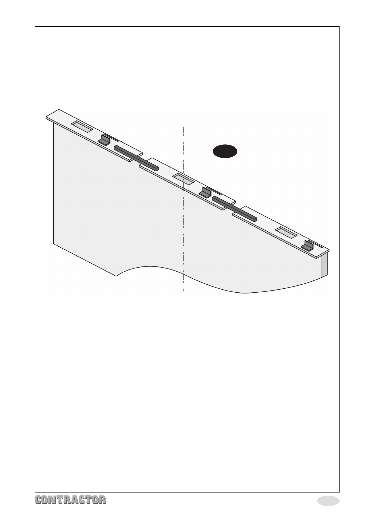
5. Attach the middle plate to the top plate as described on page 4, DO NOT tighten
wing screw at this stage.
6. Attach the bottom plate to the middle plate, adjust the bottom plate so that it is flush
with the end of the door, tighten the wing screw and secure to the door with ‘G’ clamp
(Fig. 7a and 7b). Ensure clamp does not obstruct router path.
7. Adjust the middle plate so that the middle aperture is in the centre of the door, (Fig. 8)
tighten the wing screw and secure to door with ‘G’ clamp. Ensure clamp does not
obstruct router path.
Fig. 8
8. Ensure all wing screws and ‘G’ clamps are tight, check aperture positions are correct
and adjust if necessary. Ensure the door is firmly supported, i.e. using folding work bench
or similar.
Routing Hinge Recesses In The Door.
Assemble and adjust router as follows (always refer to manufacturers instructions).
1. Remove all attachments if fitted, i.e. fence guide etc.
2. Fit 16mm guide bush.
3. Fit ½” (12.7mm) router cutter.
4. Attach dust/chip extractor.
5. Adjust the depth of cut just slightly deeper than the hinge thickness.
6. Position the router on the jig with the guide bush inside one of the apertures.
7. Holding the router with both hands, ensure it is sitting flat on the jig. Switch ON and
plunge to the preset depth, move the router in a clockwise direction allowing the
guide bush to follow the jig aperture until the recess is completely cut out.
8. Square off the corners with a sharp chisel.
9. Repeat steps 6,7 & 8 for other two recesses.
NOTE: If only fitting, top and bottom hinges, DO NOT rout out the centre aperture.
-6-
Page 8
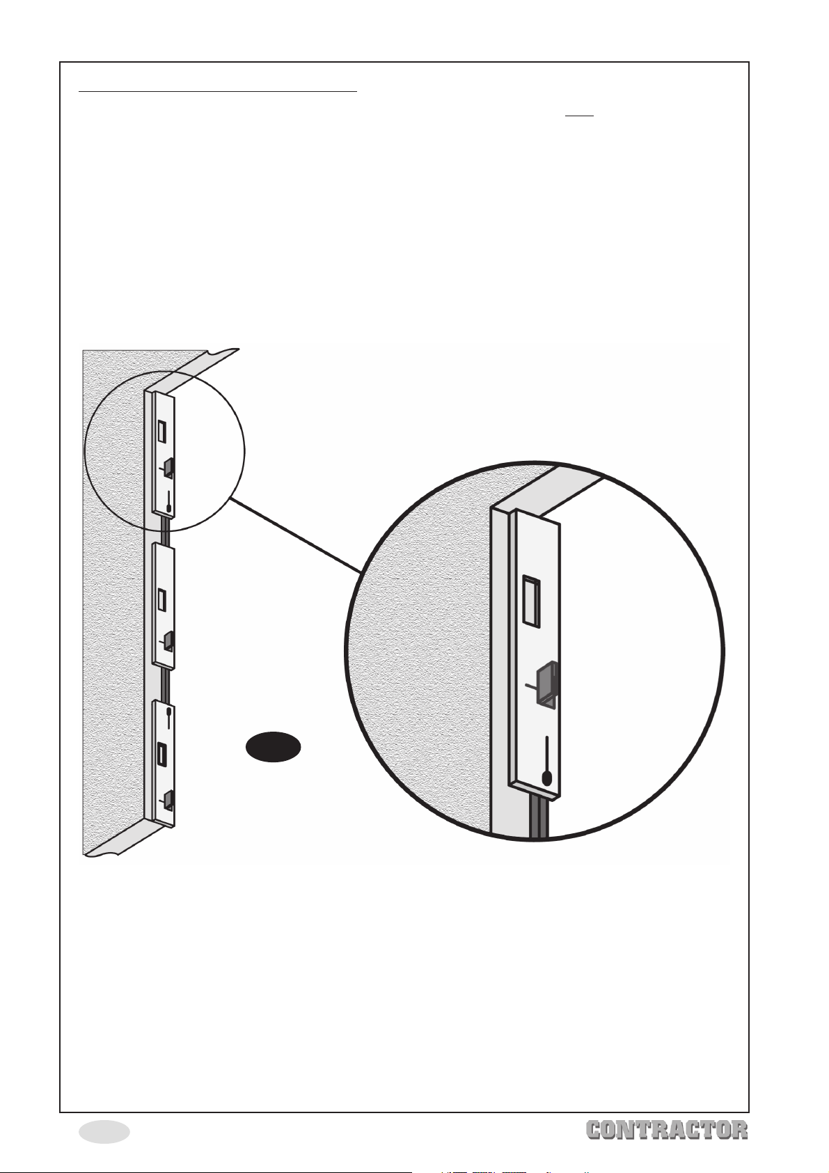
Routing Hinge Recesses In The Frame.
1. Carefully remove the hinge jig from the door without releasing
any wing screws and
taking care not to disturb the jig settings.
2. Loosen the securing screw in the swivel and turn it back 90º so that it is in line with the
top plate again, tighten securing screw.
3. Place the hinge jig against the door frame, using the opposite side of the jig used on
the door (see Fig. 9). Ensure the jig is pushed up to the top of the door frame, i.e. the
swivel securing screw is touching the top of the frame (see inset below).
4. Using the ‘G’ clamps secure the jig to the frame in the same way as with the door. If it
is not possible to use the ‘G’ clamps, the jig can be secured to the frame using suitable
woodscrews through the holes in the jig plates.
Fig. 9
5. Rout the hinge recesses following the instructions for routing out the door recesses
(page 6 steps 6, 7 &8).
Finally fit hinges and hang door.
If jig is not to be used again, disassemble and store carefully.
NOTE: it is not necessary to remove the aligning/clamping sets for storing and carrying.
-7-
Page 9

-8-
Page 10
 Loading...