

Page 1
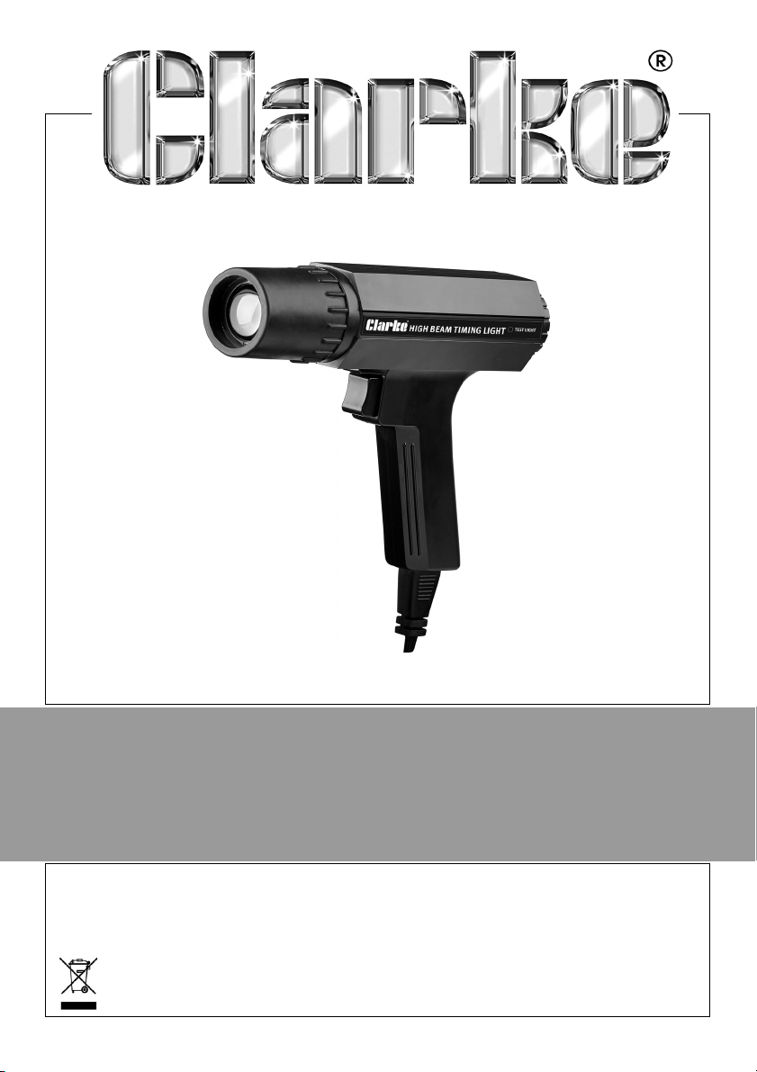
HIGH BEAM TIMING LIGHT
MODEL NO: CHBTL1
PART NO: 4003402
USER INSTRUCTIONS
ORIGINAL INSTRUCTIONS GC1219 - ISS 1
Page 2

INTRODUCTION
Thank you for purchasing this CLARKE Timing Light.
Before use, read the following information we are sure that you will enjoy
many years of service from your timing light and maintain the efficiency of
your car engine.
The Xenon bulb used in this light will provide the bright flash needed to see
engine timing marks under bright lighting conditions including daylight. The
bulb can be replaced by the user when necessary, reducing the need to
return the light to your CLARKE dealer for repair.
CONTENTS
PAG E
BASICS OF ENGINE TIMING.. . . . . . . . . . . . . . . . . . . . . . . . . . . . . . . .
When to check timing . . . . . . . . . . . . . . . . . . . . . . . . . . . . . . .
Timing specifications . . . . . . . . . . . . . . . . . . . . . . . . . . . . . . . .
SAFETY PRECAUTIONS . . . . . . . . . . . . . . . . . . . . . . . . . . . . . . . . . . . .
GENERAL OPERATING PROCEDURES . . . . . . . . . . . . . . . . . . . . . . .
Using an advance timing light . . . . . . . . . . . . . . . . . . . . . . ..
Adjusting timing to specifications . . . . . . . . . . . . . . . . . . . .
Testing centrifugal advance . . . . . . . . . . . . . . . . . . . . . . . . .
Testing vacuum advance . . . . . . . . . . . . . . . . . . . . . . . . . . . .
Checking distributor cam wear . . . . . . . . . . . . . . . . . . . . . .
Small engines . . . . . . . . . . . . . . . . . . . . . . . . . . . . . . . . . . . . . . .
Rotary engines . . . . . . . . . . . . . . . . . . . . . . . . . . . . . . . . . . . . . .
FAULTFINDING . . . . . . . . . . . . . . . . . . . . . . . . . . . . . . . . . . . . . . . . . . .
CARE AND MAINTENANCE . . . . . . . . . . . . . . . . . . . . . . . . . . . . . . . .
Replacing the xenon lamp . . . . . . . . . . . . . . . . . . . . . . . . . .
ENVIRONMENTAL RECYCLING POLICY . . . . . . . . . . . . . . . . . . .. .
GUARANTEE . . . . . . . . . . . . . . . . . . . . . . . . . . . . . . . . . . . . . . . . . . . .
3
3
5
6
7
8
9
10
10
11
11
11
13
14
14
15
15
2
Parts & Service: 020 8988 7400 / E-mail: [email protected] or [email protected]
Page 3

BASICS OF ENGINE TIMING
In order for an automobile engine to function, three things are necessary: air,
fuel and a spark to ignite the air/fuel mixture and create an explosion. The
precise instant of that explosion must be such that the maximum power is
delivered to the engine piston. This is ”timing”. Each engine manufacturer
determines the exact timing necessary for various engines so that optimum
power is obtained from the fuel used. Due to normal engine and ignition
system wear, the accuracy of the timing can be lost, reducing both power
and fuel mileage. With the timing light, the timing can be reset to new car
standards and regain lost power and fuel mileage.
Timing is given in degrees Before Top Dead Center (BTDC) or After Top Dead
Center (ATDC) in the manufacturer's specifications.
In order to completely burn the air/fuel mixture in the engine cylinders, most
timing is such that the spark occurs at a point several degrees before top
dead center (for example, 4° BTDC) to ensure the full power of the explosion is
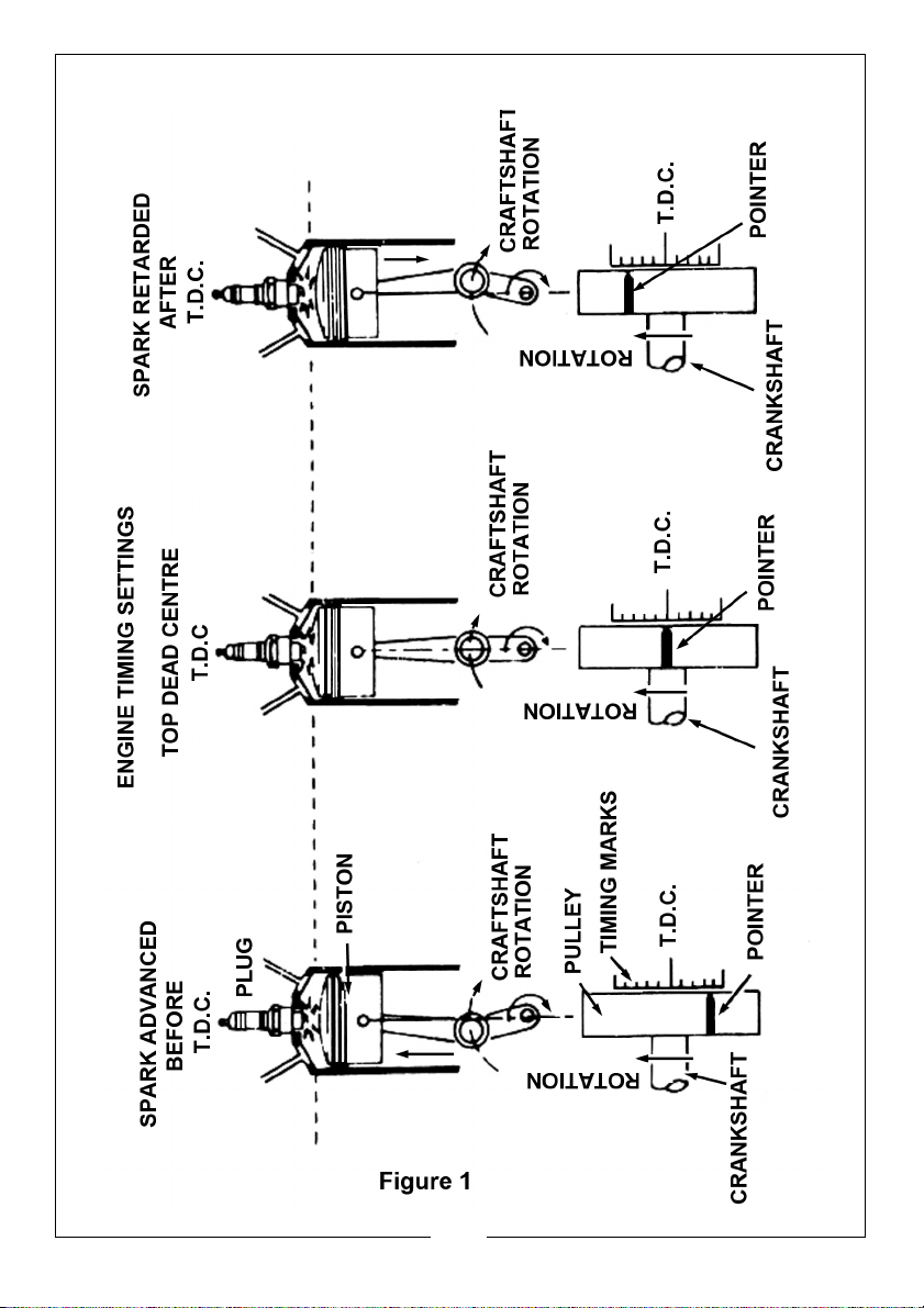
obtained. See Figure 1 on page 4.
Two additional terms the engine manufacturers use when describing timing
are "Advanced" and "Retarded". As shown in Figure 1 on page 4, when the
timing is advanced, the spark will occur before the piston reaches the top of
the engine cylinder (BTDC). On some late model cars equipped with various
emission control devices, the timing is retarded so that the spark occurs after
the piston has started to move down in the cylinder (ATDC). Engine timing is
changed by adjustment of the ignition distributor.
In order to allow setting and adjustment of the engine timing, special timing
marks are provided on the engine during assembly. In most cases, these marks
appear on the engine vibration damper or fan pulley at the lower front of the
engine. See Figure 1 on page 4. On some early engines, this mark was shown
at the rear of the engine on the flywheel.
WHEN TO CHECK TIMING
The instant of spark plug firing is determined by the opening of the distributor
ignition breaker points and will change any time the point gap or dwell angle
is changed. In addition, normal wear on the contact breaker points will
change the dwell and affect the timing. While cars equipped with the modern
contact breakerless electronic ignition systems will not normally change timing
since there are no contact breaker points, the timing light can still be used to
note changes in timing caused by faults in the ignition system as well as for
resetting timing when components are replaced.
3
Parts & Service: 020 8988 7400 / E-mail: [email protected] or [email protected]
Page 4
Page 5
TIMING SPECIFICATIONS
Timing requirements vary from engine to engine and therefore the engine
manufacturers specifications should always be referred to before making any
adjustments.
These specifications are contained in the car owners manual, on the engine
bay label (required on all cars manufactured since 1968) and in various
publications. Many spark plug manufacturers such as Champion, Autolite and
others also provide specifications.
5
Parts & Service: 020 8988 7400 / E-mail: [email protected] or [email protected]
Page 6

SAFETY PRECAUTIONS
1. DO NOT smoke, strike a match, or cause a spark in vicinity of the engine.
2. Remove all rings, bracelets, necklaces, and watches while working with a
vehicle engine.
3. Take care not to drop a metal tool onto the battery or onto the moving
parts of the engine.
4. DO NOT place the timing light on the hot engine surface and avoid the
engine fan, fan belt or battery to prevent damage.
5. Take care when clipping the clamp to the spark plug lead. Risk of electric
shock if the engine is running.
6. Take care of any moving parts such and drive belts etc.
7. DO NOT look directly at the timing light.
6
Parts & Service: 020 8988 7400 / E-mail: [email protected] or [email protected]
Page 7

GENERAL OPERATING PROCEDURES
CAUTION: TAKE CARE WHEN WORKING AROUND A MOVING ENGINE.
KEEP HANDS, TOOLS AND THE TIMING LIGHT CLEAR OF MOVING FAN,
BELTS OR OTHER MOVING PARTS.
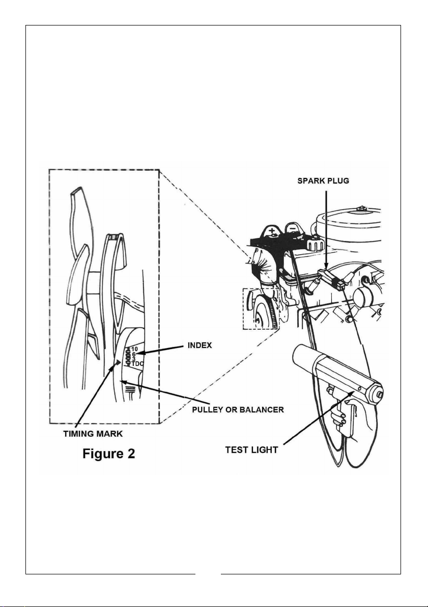
1. Locate the engine timing mark shown in figure 2 on page 5, and use a rag
to clean any grease and dirt from the mark and the pointer. It may help to
use chalk or white paint on the marks to make them more easily seen.
2. Check the manufacturers specifications for correct timing for the engine
being serviced.
3. Start and run the engine until its normal operating temperature is reached.
(approximately 15 minutes) and stop the engine.
4. If specifications require, locate the vacuum tube going to the ignition
distributor vacuum advance.
5. Disconnect and block the tube. A golf tee or small pencil may be used to
block the tube.
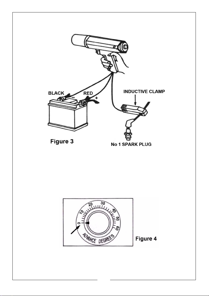
6. Connect the timing light as shown in figure 3 on page 8.
7. Start the engine and operate at normal idle speed. Aim the timing light at
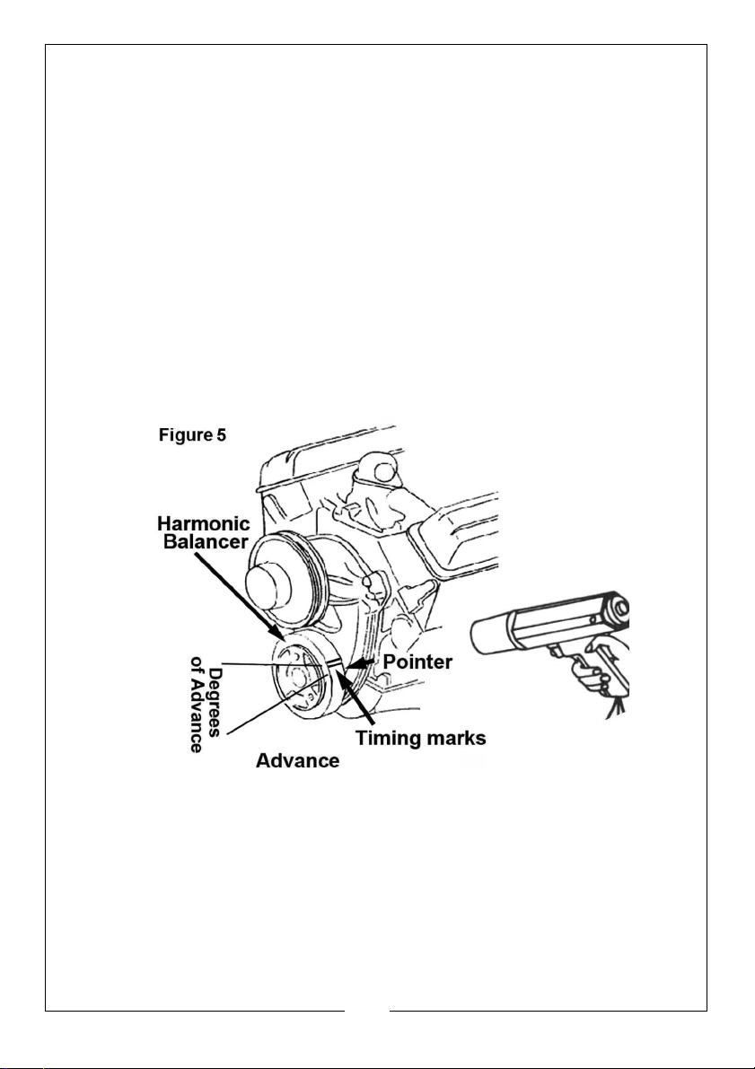
the timing mark as figure 5 on page 9.
8. Trigger the timing light and observe the reading from the timing mark.
• If the connection at any of the terminals or at the inductive clamp are
not satisfactory, this will be indicated by the test light on the side of the
unit.
9. Compare the reading obtained in step 8 with the manufacturers
specification. If the timing is not as specified re-adjust as described in the
following procedure (Adjusting the Timing to Specification)
10. Stop the engine.
7
Parts & Service: 020 8988 7400 / E-mail: [email protected] or [email protected]
Page 8
USING AN ADVANCE TIMING LIGHT
CHECKING THE "IDLE TIMING"
1. Set the knob at "0" position as figure 4.
2. Follow the General Operating Procedures on page 7.
8
Parts & Service: 020 8988 7400 / E-mail: [email protected] or [email protected]
Page 9
CHECKING THE "CENTRIFUGAL ADVANCE" & "VACUUM ADVANCE"
1. Follows the steps 1 to 6 of General Operating Procedures on page 7
except for increasing the engine speed to 2000 rpm.
2. Trigger the timing light and rotate the knob clockwise slowly and stop when
the timing mark moves to "T.D.C." position.
3. Observe the reading from advance scale as shown on figure 4.
4. Compare the reading with the manufacturer's specifications.
ADJUSTING THE TIMING TO SPECIFICATION
1. Loosen the distributor hold-down locking bolts located at base of the
distributor so that the distributor may be rotated back and forth. Do not
overloosen or remove the bolts but leave them tight enough to prevent the
distributor from turning by itself.
2. Start and run the engine.
3. Direct the timing light flash at the timing marks and slowly rotate the
distributor right or left until the timing marks are aligned with the pointer.
Stop the engine.
4. Tighten the distributor hold-down bolt taking care not to change the
position of the distributor.
5. Start the engine and recheck the timing.
9
Parts & Service: 020 8988 7400 / E-mail: [email protected] or [email protected]
Page 10
TESTING CENTRIFUGAL ADVANCE
With the timing light still connected and with the vacuum line disconnected:
1. Speed the engine up slowly to the manufacturers recommended speed
and watch the timing mark.
2. The timing mark should remain stationary until the engine reaches the
manufacturer's specified speed. The timing mark should then move
steadily. (See figure 5 on page 9)
3. If the mark does not move or if it moves erratically, the centrifugal
(automatic) advance should be serviced as necessary.
4. To check the maximum advance it is necessary to mark the harmonic
balancer with the maximum degree per the manufacturer's specifications
and follow the manufacturer's procedures.
TESTING VACUUM ADVANCE
1. The vacuum line to the distributor must be connected to make this test.
2. Set the engine speed to 800 RPM or a speed necessary to apply vacuum
to the distributor.
3. Aim the timing light and note the position of the timing mark.
4. Disconnect the vacuum tube.
5. If the timing mark does not move, the fault could be a blocked vacuum
tube, a leaky diaphragm or a seized distributor plate and the distributor
should be serviced as required.
10
Parts & Service: 020 8988 7400 / E-mail: [email protected] or [email protected]
Page 11

CHECKING DISTRIBUTOR CAM WEAR
1. This check is done after the timing has been set and the timing mark lines
up with the reference pointer for No 1 cylinder.
2. Connect the timing light to the wire directly opposite (180°) No 1 cylinder
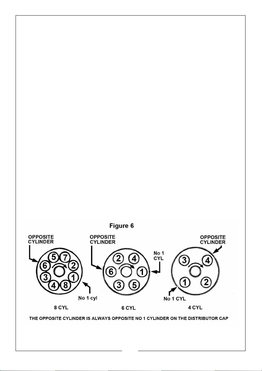
on the distributor cap. (See figure 6 on page 10)
3. Start engine and aim the timing light towards the timing mark. The reading
should be the same as when connected to No 1 cylinder.
4. If reading is not the same, probable cause is worn out distributor cam or
bent distributor shaft. Repair as required.
SMALL ENGINES
The DC power timing light can be used on any combustion engine with
impulse ignition, magneto ignition, such as motorcycles, lawn mowers,
outboard motors, or any time there is a high voltage spark used for ignition.
When 12 Volt DC voltage is not available from the engine being tested, an
external battery of 12V must be used. Connect a ground from the negative
post of the external battery to the engine. Connect the red clip to the (+)
positive terminal and the black clip to the (-) negative terminal of the battery.
Connect the adaptor lead of the timing light to the correct spark plug.
ROTARY ENGINES
The timing light can be used on rotary engines.
Follow the manufacturer's specific instructions and specifications. Figure 7 on
page 12 shows a typical procedure for the Mazda twin rotor engine.
1. Connect the red (+) and black (-) power lead clamps to the battery.
Connect wire with the spark plug adaptor to the leading spark plug on the
front rotor housing.
2. Start the engine and run at idle speed.
3. Aim the timing light at the timing indicator pin on the front cover.
4. Loosen the distributor locking nuts and rotate the leading side distributor
body until the timing mark on the eccentric shaft pulley are in line with the
timing indicator pin.
5. Tighten the locking nuts and re-check the timing.
11
Parts & Service: 020 8988 7400 / E-mail: [email protected] or [email protected]
Page 12
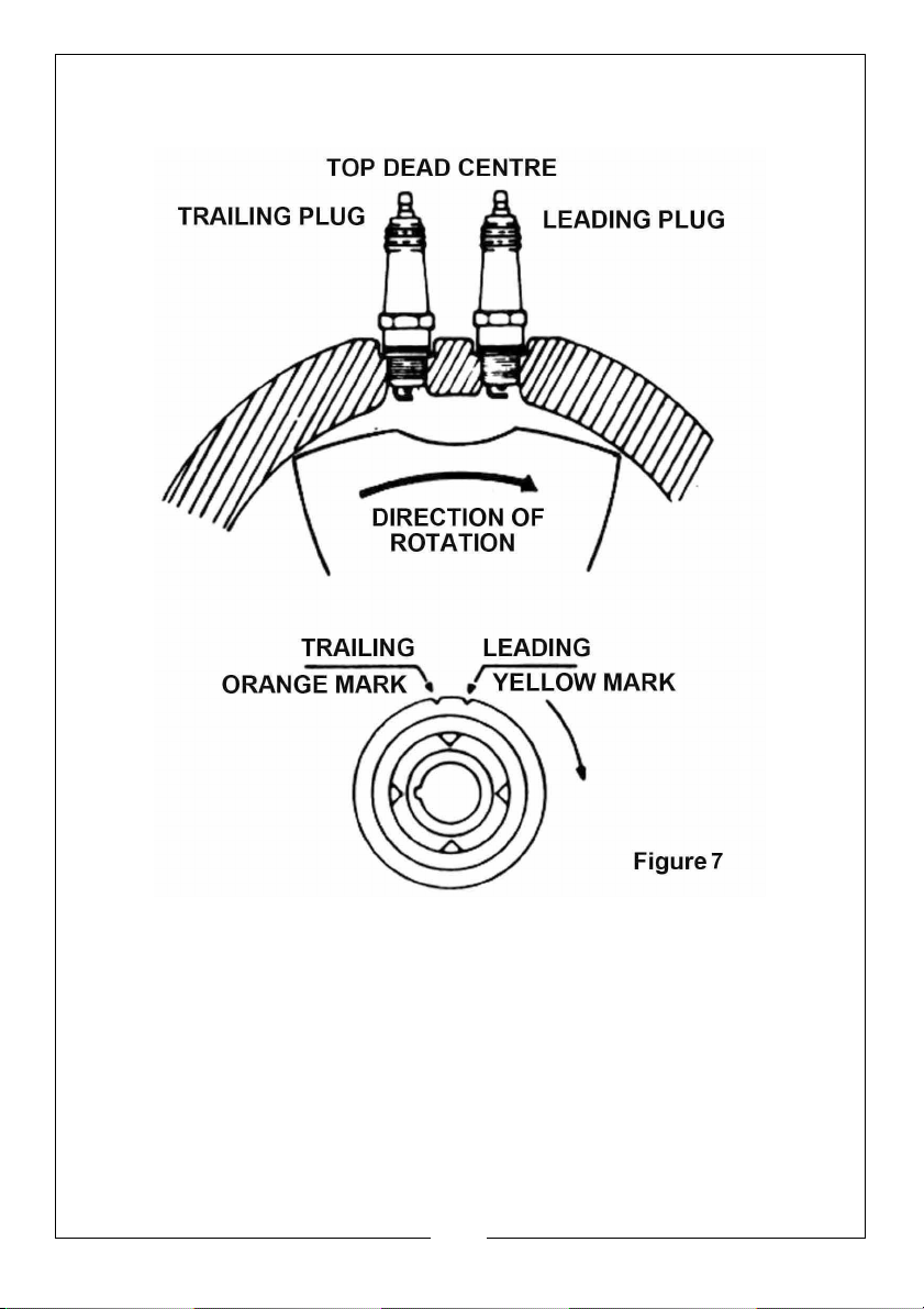
6. Repeat the above step for setting the trailing side distributor timing with the
timing light connected to the trailing spark plug.
12
Parts & Service: 020 8988 7400 / E-mail: [email protected] or [email protected]
Page 13
FAULTFINDING
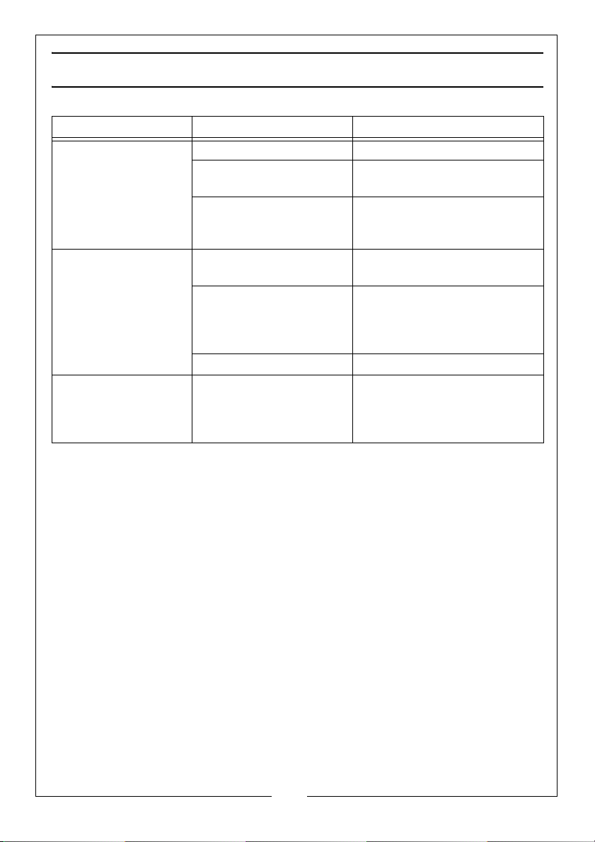
Symptom Probable Cause Solution
No flash Trigger in OFF position Set trigger to ON position
Battery clips connected
in reverse
Poor connection of clips Make sure the clips are
No flash but double
check indicator is ON
Light flashes
intermittently
All timing lights are tested before they are shipped from the factory and
improper operation is usually caused by incorrect connection. Please observe
the above troubleshooting procedure if the timing light fails to perform
satisfactorily.
Wrong direction of
inductive clamp
Weak ignition or spark
plug. Plug gap is too
small
Faulty lamp Replace it
Timing light high tension
lead lying on or too close
to the other spark plug
leads.
Reverse the battery clip
connections
connected to a clean battery
terminal
Point the arrow on the clamp
towards the plug
Connect to other plugs or
spark plug leads. If light
flashes, then repair the bad
plug or correct the gap.
Place the high tension lead so
that it is routed away from the
other plug leads.
13
Parts & Service: 020 8988 7400 / E-mail: [email protected] or [email protected]
Page 14
CARE AND MAINTENANCE
Always keep the unit clean including the lamp lens.
Keep the clamps clean and the cables tidy.
Always check for splits or cuts in the cables.
XENON LAMP REPLACEMENT
If the fault finding procedures do not correct the fault the most probable
cause is a defective xenon lamp.
The lamp may have a black spot around the anode, this is perfectly normal.
However, if the lamp is completely black it has reached its end of life and
should be replaced.
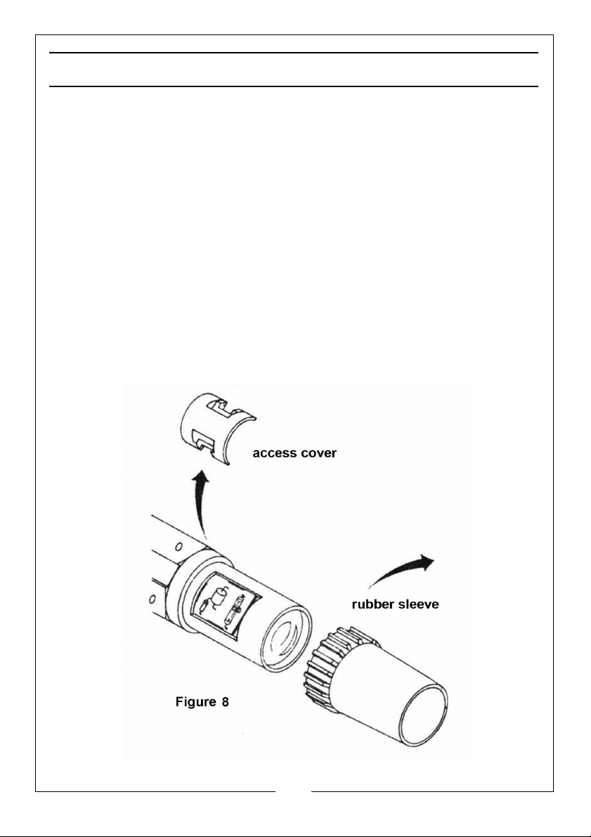
Draw the rubber sleeve off the end of the timing light body to expose the
lamp access cover. This can be lifted away and the bulb replaced. (See
Figure 8)
• Take care when handling new lamps and avoid touching them with
bare hands.
14
Parts & Service: 020 8988 7400 / E-mail: [email protected] or [email protected]
Page 15
ENVIRONMENTAL RECYCLING POLICY
Through purchase of this product, the customer is taking on the
obligation to deal with the WEEE in accordance with the WEEE
regulations in relation to the treatment, recycling & recovery and
environmentally sound disposal of the WEEE.
In effect, this means that this product must not be disposed of with general
household waste. It must be disposed of according to the laws governing
Waste Electrical and Electronic Equipment (WEEE) at a recognised disposal
facility.
GUARANTEE
This CLARKE product is guaranteed against faulty manufacture for a period of
12 months from the date of purchase. Please keep your receipt as proof of
purchase.
This guarantee is invalid if the product is found to have been abused or
tampered with in any way, or not used for the purpose for which it was
intended.
Faulty goods should be returned to their place of purchase, no product can
be returned to us without prior permission.
This guarantee does not effect your statutory rights.
15
Parts & Service: 020 8988 7400 / E-mail: [email protected] or [email protected]
Page 16
 Loading...