

Page 1
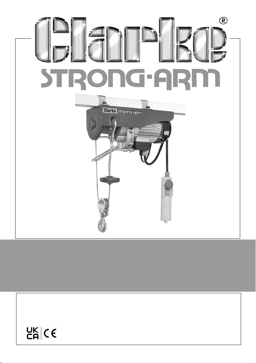
ELECTRIC HOIST
MODEL NO: CH2500C, CH4000C
PART NO: 7630388, 7630393
OPERATION AND MAINTENANCE
INSTRUCTIONS
ORIGINAL INSTRUCTIONS GC03/23 - rev 1
Page 2
INTRODUCTION
Thank you for purchasing this CLARKE Electric Hoist.
Before attempting to use this product, please read this manual thoroughly and
follow the instructions carefully. In doing so you will ensure the safety of yourself
and that of others around you, and you can look forward to your purchase
giving you long and satisfactory service.
LIFTING OPERATIONS AND LIFTING EQUIPMENT REGULATIONS 1998
This hoist, depending on use, may fall within the scope of LOLER. It is the
owner’s responsibility to determine whether or not it does and, if so, to comply
with any applicable requirements in LOLER, for having the hoist thoroughly
examined.
GUARANTEE
This product is guaranteed against faulty manufacture for a period of 12
months from the date of purchase. Please keep your receipt which will be
required as proof of purchase.
This guarantee is invalid if the product is found to have been abused or
tampered with in any way, or not used for the purpose for which it was
intended.
Faulty goods should be returned to their place of purchase, no product can
be returned to us without prior permission. This guarantee does not effect your
statutory rights.
ENVIRONMENTAL PROTECTION
Through purchase of this hoist, the customer is taking on the
obligation to deal with the WEEE in accordance with the WEEE
regulations in relation to the treatment, recycling & recovery and
environmentally sound disposal of the WEEE.
In effect, this means that this hoist must not be discarded with general waste.
Refer to the laws governing Waste Electrical and Electronic Equipment (WEEE)
at a recognised disposal facility.
2
Parts & Service: 020 8988 7400 / E-mail: [email protected] or [email protected]
Page 3
SPECIFICATIONS
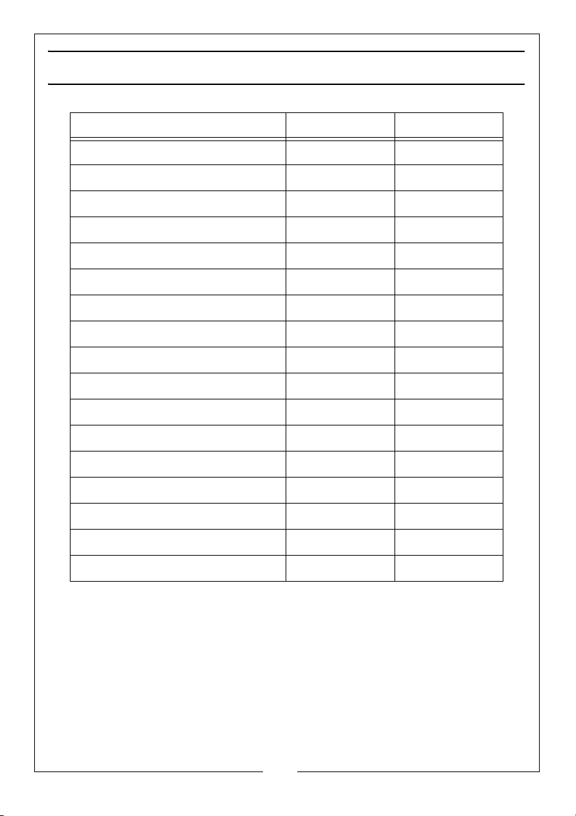
CH2500C CH4000C
Part Number 7630388 7630393
Load Capacity (Single Cable) 125 kg 200 kg
Lifting Speed (Single Cable)
Lifting Height (Single Cable) 12 m 12 m
Load Capacity (Double Cable) 250 kg 400 kg
Lifting Speed (Double Cable) 5 m/min 5 m/min
Lifting Height (Double Cable) 6 m 6 m
Cable Length 12 m 12 m
Cable Diameter 3 mm 3.8 mm
Duty Cycle S3 20% - 10min S3 20% - 10min
Electrical Supply 230V @ 50Hz 230V @ 50Hz
Power Rating 540 W 950 W
Ingress Protection IP54 IP54
Sound Pressure Level 74.3 dB(A) 74.3 dB(A)
Sound Power Level 75.3 dB(A) 76.3 dB(A)
Sound Power Level Guaranteed 85dB 85dB
Uncertainty K 2 dB(A) 2 dB(A)
10 m/min 10 m/min
DO NOT LEAVE THE HOIST EXPOSED TO THE ELEMENTS AND AVOID DIRECT SUNLIGHT, DIRECT HEAT AND MOISTURE
THIS MACHINE IS FOR INDOOR USE ONLY
3
Parts & Service: 020 8988 7400 / E-mail: [email protected] or [email protected]
Page 4
GENERAL SAFETY RULES
There is a serious risk of personal injury if you do not follow all instructions in this
guide.
1. This hoist must only be used by a competent person who understands these
instructions.
2. This hoist is for indoor, non-industrial use.
3. Keep children, animals and bystanders away from the work area.
4. DO NOT use this hoist if you are ill, tired, or under the influence of alcohol or
drugs.
5. Before use, always examine the hoist and its mountings to make sure that
they are in good condition. If you find any damaged or broken parts,
withdraw the hoist from service and renew or repair the part before further
use.
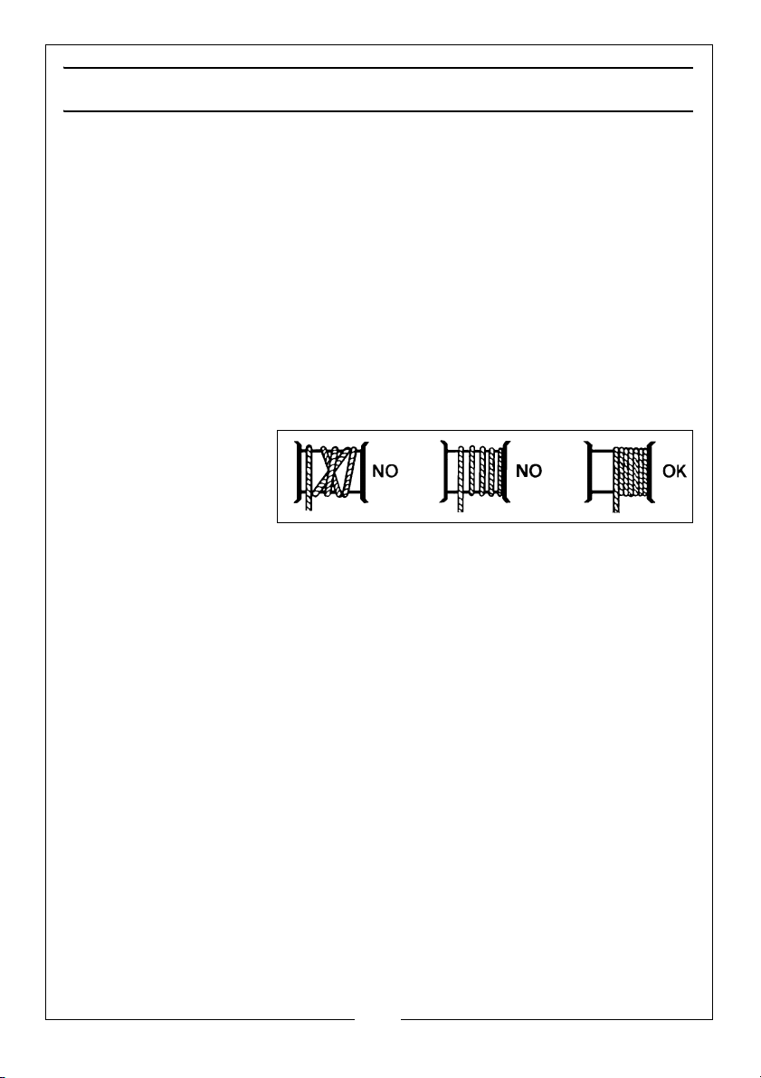
6. Before use, it is
important to make
sure that the steel
cable is correctly
wound around the
drum.
7. Wear protective clothing, gloves, footwear and hard hat.
8. DO NOT wear loose clothing, jewellery and tie back long hair.
9. Protect the equipment from frost or excessively high temperatures.
10. If the capacity of the hoist is exceeded, the cutout will operate. Let the
components cool down before continued use.
11. Make sure that the load is balanced, stable and that all personnel stay
clear of the raised load.
12. Make sure that the switches are in good condition.
13. Use this hoist for vertical lifts only.
14. Attach the hoist to a horizontal beam/box section that can hold the
weight of the load and the hoist.
15. When replacing parts, use only those supplied by Clarke International.
Consult the CLARKE service department for any spare parts required.
4
Parts & Service: 020 8988 7400 / E-mail: [email protected] or [email protected]
Page 5
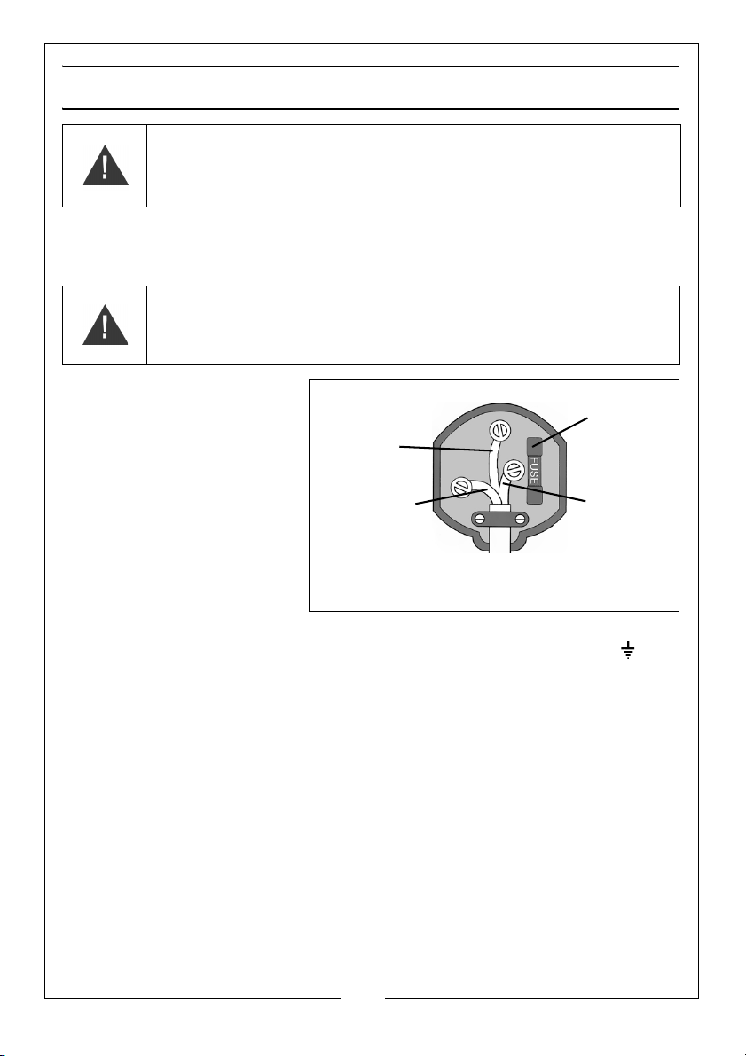
ELECTRICAL CONNECTIONS
Plug must be BS1363/A approved.
Always fit
make sure that the outer sheath of
Neutral
(Blue)
Live
(Brown)
Earth
(Green and
a 13 Amp
the cable is firmly held by the clamp
fuse.
Yel low)
WARNING: READ THESE ELECTRICAL SAFETY INSTRUCTIONS FULLY
BEFORE CONNECTING THE HOIST TO THE MAINS SUPPLY.
This hoist is provided with a standard 13 amp, 230 volt (50Hz), BS 1363 plug, for
connection to a standard, domestic electrical supply. Should the plug need
changing, make sure that a plug of identical specification is used.
WARNING: THE WIRES IN THE CABLE ARE COLOURED AS FOLLOWS:
BLUE = NEUTRAL BROWN = LIVE YELLOW AND GREEN = EARTH
If the colours of the wires in
the power cable do not
correspond with the
markings on the terminals of
your plug, proceed as
follows.
• Connect the blue wire
to the terminal
marked N.
• Connect the brown
wire to the terminal
marked L.
• Connect the yellow and green wire to the terminal marked E or .
AN APPROVED RESIDUAL CURRENT DEVICE (RCD) WHICH HAS A TRIPPING
CURRENT OF LESS THAN 30MA MUST BE USED.
If you are not sure, consult a qualified electrician. DO NOT try to do any
repairs.
Parts & Service: 020 8988 7400 / E-mail: [email protected] or [email protected]
5
Page 6
UNPACKING
Unpack the box and make sure that the items in the list below are included.
• 1 x Hoist
• 1 x Hook / Pulley
•2 x Brackets
• 1 x Bag of fixings
• 1 x Instruction manual
If a part is damaged, consult your CLARKE supplier immediately.
INSTALLATION
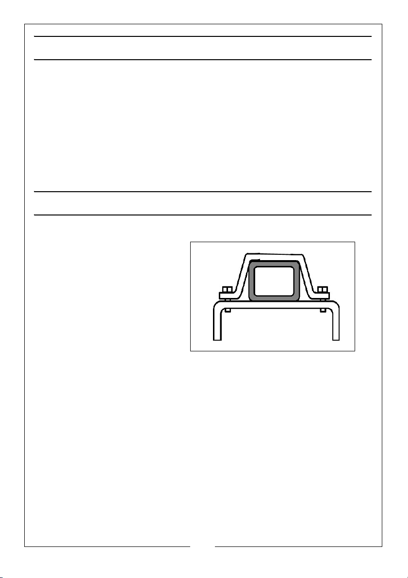
Mount the hoist to a box section beam using the brackets supplied.
• The box section must be
able to support the weight
of the hoist plus the
maximum specified load.
If you are not sure, consult an
approved structural engineer.
6
Parts & Service: 020 8988 7400 / E-mail: [email protected] or [email protected]
Page 7
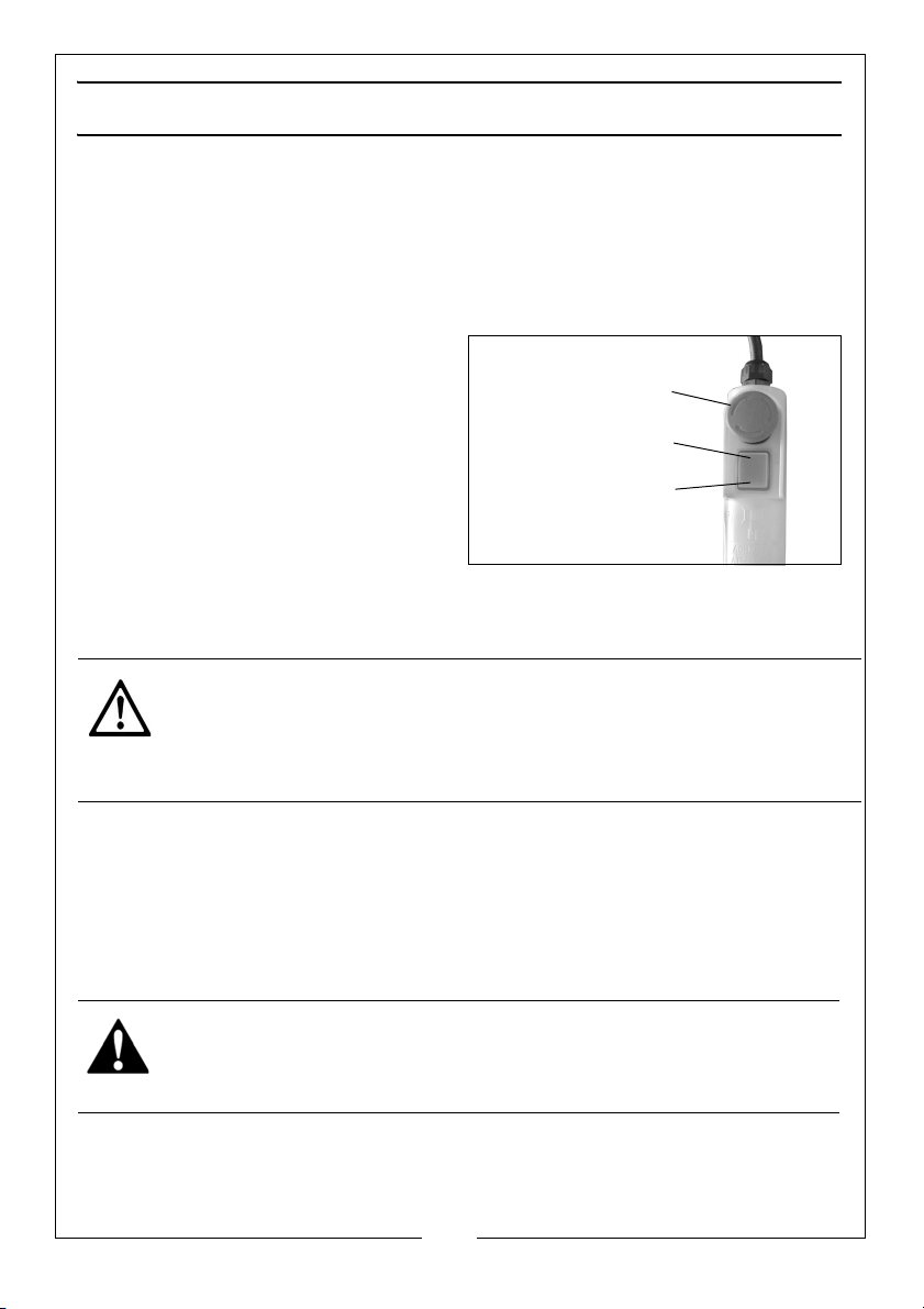
OPERATION
EMERGENCY STOP
LIFT
LOWER
PRE-USE INSPECTION
Unwind the cable and examine for fraying, corrosion etc.
Check the condition of all brackets and fastenings.
When in constant operation, the hoist should be inspected frequently.
HOIST CONTROL
LIFT/LOWER SWITCH
1. Press one side of the rocker switch
to lift the load.
2. Press the other side of the rocker
switch to lower the load.
3. To stop the hoist release the
switch.
NOTE: The load will not stop immediately when you release the switch. It
can continue for a 3-4 mm before the motor brake takes effect.
CAUTION: MAKE SURE THE HOIST HAS STOPPED BEFORE MOVING IN THE
OPPOSITE DIRECTION.
CAUTION: THIS HOIST IS FITTED WITH AN AUTO-STOP DEVICE. ENSURE THAT
WHEN THE CABLE IS AT ITS HIGHEST POINT AND THE AUTO-STOP IS
ACTUATED, THAT THE LIFT SWITCH IS RELEASED.
EMERGENCY STOP
Push the emergency stop to stop the hoist in an emergency.
• The emergency stop can be reset by turning it clockwise until it
‘pops’ out.
USING THE HOIST
WARNING: LIFTING OPERATIONS MUST BE PLANNED, SUPERVISED AND
CARRIED OUT SAFELY BY COMPETENT PERSONNEL.
1. Pay out the cable.
• Keep the cable in tension so that the coils on the drum remain
neatly in place.
Parts & Service: 020 8988 7400 / E-mail: [email protected] or [email protected]
7
Page 8
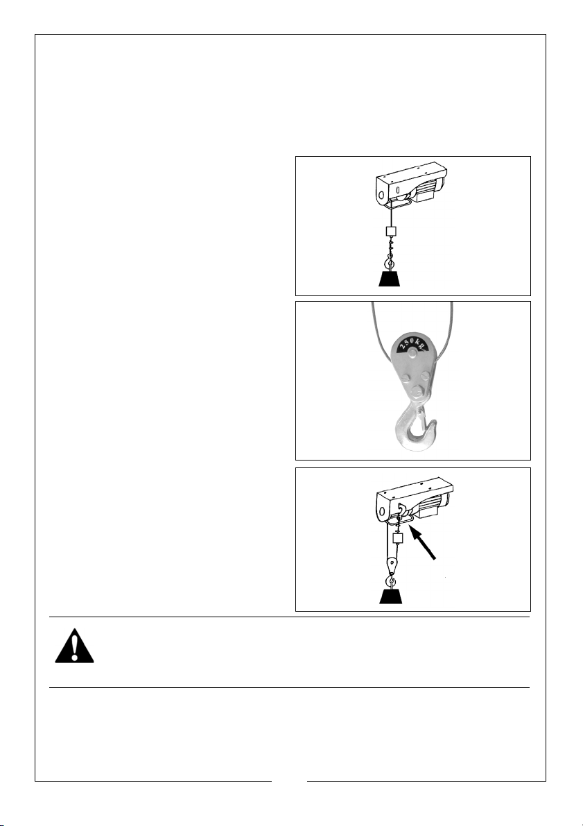
2. Attach the hook to the load. The hook must be placed -
• Directly above the centre of gravity of the load and in line with the
hoist.
• Make sure that no obstruction will prevent a clean lift.
HOIST CAPACITY
In the basic setup (shown on the
right) the lifting capacity is 125 kg,
(200 kg for the CH4000C)
It is possible to increase the capacity
to 250 kg (400 kg for the CH4000C). To
do this:
1. Loop the cable around the pulley
supplied.
2. Attach the hook to the hoist as
shown.
WARNING: ALWAYS LOWER IN A SLOW AND CONTROLLED MANNER, AND
ENSURE THAT THERE ARE NO OBSTACLES IN THE PATH OF THE LOAD’S
DESCENT.
8
Parts & Service: 020 8988 7400 / E-mail: [email protected] or [email protected]
Page 9
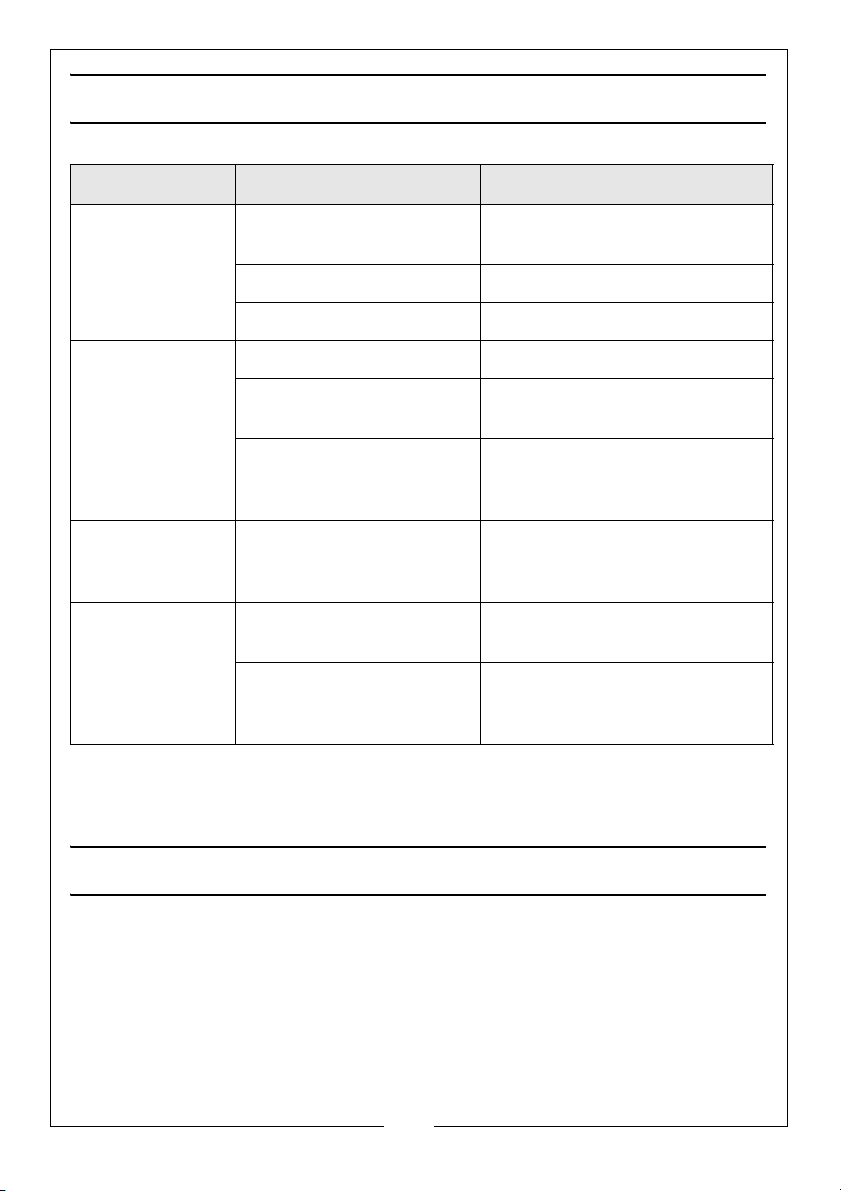
TROUBLESHOOTING
PROBLEM CAUSE SOLUTION
When you press
the switch the
motor does not
operate.
Motor hums but
does not lift
Brake does not
operate and
load slips
The cable is
twisted, frayed or
kinked
If this does not solve your problem, please consult the CLARKE service
department.
The power cable is not
plugged in correctly
The cut out has operated Let the motor cool down
Power failure Check plug fuse
The motor is too hot Let it cool down
The load exceeds the
capacity of the hoist
The motor brake has
become stuck during
storage.
Brake is worn out. DO NOT use the hoist and
Cable is incorrectly wound
on the drum.
The cable has been stored
unwound or in poor
conditions.
Connect the power cable
correctly
Decrease the load
Consult your CLARKE dealer for
advice.
consult your CLARKE dealer.
Replace the cable.
Replace the cable.
MAINTENANCE
IMPORTANT: Only fully qualified personnel should attempt repairs.
1. Always visually inspect the hoist before use, to ensure that all parts are
correctly located and secure. Check for signs of damage or worn parts. Do
not use the hoist unless it is perfectly serviceable.
2. Check the cable for signs of fraying especially at the connecting parts.
9
Parts & Service: 020 8988 7400 / E-mail: [email protected] or [email protected]
Page 10
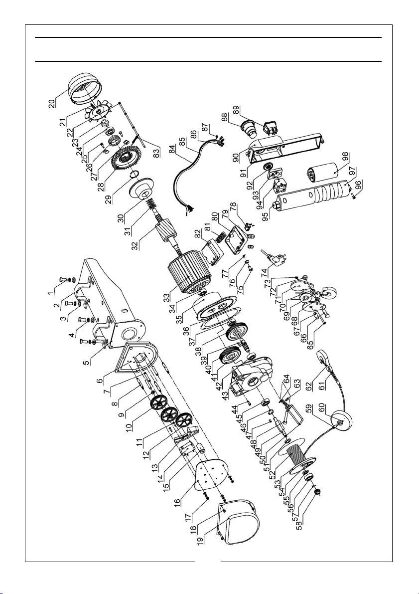
COMPONENT PARTS - CH2500C
10
Parts & Service: 020 8988 7400 / E-mail: [email protected] or [email protected]
Page 11
COMPONENT PARTS CH2500C
No Description No Description
1 Hexagon Bolt 29 Internal Circlip
2 Bracket 30 Motor Brake Disc
3 Flat Washer 31 Tripping Spring
4 Spring Washer 32 Rotor
5 Support /Carriage Casing 33 Stator Casing Assembly
6 End Panel 34 Bearing
7 Locating Shaft 35 Front Cover
8 Gear Shaft 36 Paper Gasket
9 Flat Washer 37 Bearing
10 Silent Gear 38 First Gear
11 X-Head screw 39 Flat Key
12 Driven Gear 40 Gear Shaft
13 Turn Plate 41 Second Gear
14 Limit Switch 42 Bearing
15 Axle Sleeve 43 Gear Case
16 Limit Switch Plate 44 Socket Head Cap Screw
17 Nut 45 Bearing
18 X-Head Bolt 46 O-ring
19 Gear Cover 47 Flat Key
20 Fan Housing 48 Socket Head Cap Screw
21 Fan Blade 49 Drum Shaft
22 Hex Bolt 50 Limit Switch Arm
23 Locknut 51 Drum Inner Washer
24 Bearing 52 Wire Rope
25 Socket Head Cap Screw 53 Cable Drum
26 Bearing Sleeve 54 Wedge
27 Clamp 55 Drum External Washer
28 Rear Enclosure 56 Bearing
11
Parts & Service: 020 8988 7400 / E-mail: [email protected] or [email protected]
Page 12
No Description No Description
57 Straight Pin 78 Limit Switch
58 Driving Gear 79 Cable Entry
59 Aluminium Ferrule 80 Junction Box Cover
60 Block 81 Terminal
61 Rope Thimble 82 Junction Box Base
62 Hook Assembly Complete 83 Upper Limit Spring
63 X-head Bolt 84 Connecting Cable Sleeve
64 Plastic Limit Piece 85 Connecting Cable
65 Bolt 86 Socket
66 Bolt 87 Spade Connector
67 Spindle 88 Emergency Stop Button
68 Washer 89 Rocker Switch
69 Hook 90 Pendant Casing - Front
70 Pulley Wheel 91 Pendant Seal
71 Side Plate 92 Adjusting Locknut
72 Nut 93 Switch Base
73 Locknut 94 Emergency Stop Switch
74 Mains Plug 95 Cable Entry
75 Limit Shaft 96 Screw
76 Waterproof Gland 97 Pendant Casing - Rear
77 Plastic Closing Ring 98 Capacitor
12
Parts & Service: 020 8988 7400 / E-mail: [email protected] or [email protected]
Page 13
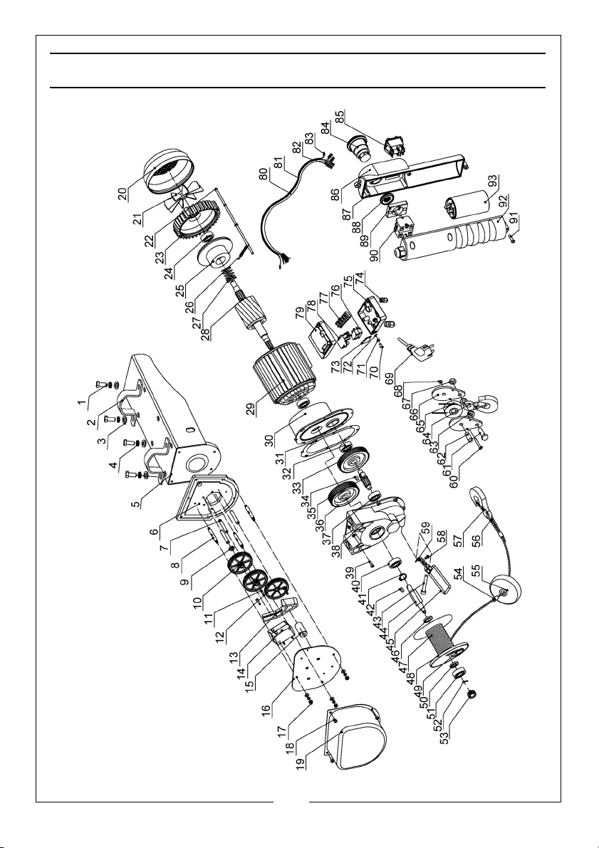
COMPONENT PARTS - CH4000C
13
Parts & Service: 020 8988 7400 / E-mail: [email protected] or [email protected]
Page 14
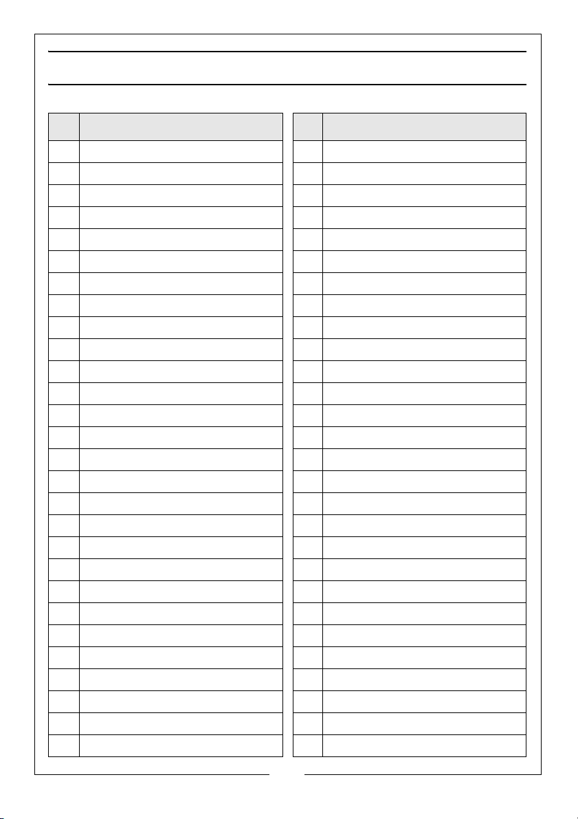
COMPONENT PARTS CH4000C
No Description No Description
1 Hexagon Bolt 29 Stator Casing Assembly
2 Bracket 30 Front Cover
3 Spring Washer 31 Paper Gasket
4 Flat Washer 32 Bearing
5 Support /Carriage Casing 33 First Gear
6 End Panel 34 Flat Key
7 Locating Shaft 35 Gear Shaft
8Gear Shaft 36Second Gear
9 Flat Washer 37 Bearing
10 Silent Gear 38 Gear Case
11 X-Head screw 39 Socket Head Cap Screw
12 Driven Gear 40 Bearing
13 Turn Plate 41 Circlip
14 Limit Switch 42 Flat Key
15 Axle Sleeve 43 Socket Head Cap Screw
16 Limit Switch Plate 44 Drum Shaft
17 Nut 45 Limit Switch Arm
18 X-Head Bolt 46 Drum Inner Washer
19 Gear Cover 47 Wire Rope
20 Fan Housing 48 Cable Drum
21 Fan Blade 49 Wedge
22 Hex Bolt 50 Drum External Washer
23 Rear Enclosure 51 Bearing
24 Bearing 52 Straight Pin
25 Motor Brake Disc 53 Driving Gear
26 Tripping Spring 54 Aluminium Ferrule
27 Spring 55 Block
28 Rotor 56 Rope Thimble
14
Parts & Service: 020 8988 7400 / E-mail: [email protected] or [email protected]
Page 15
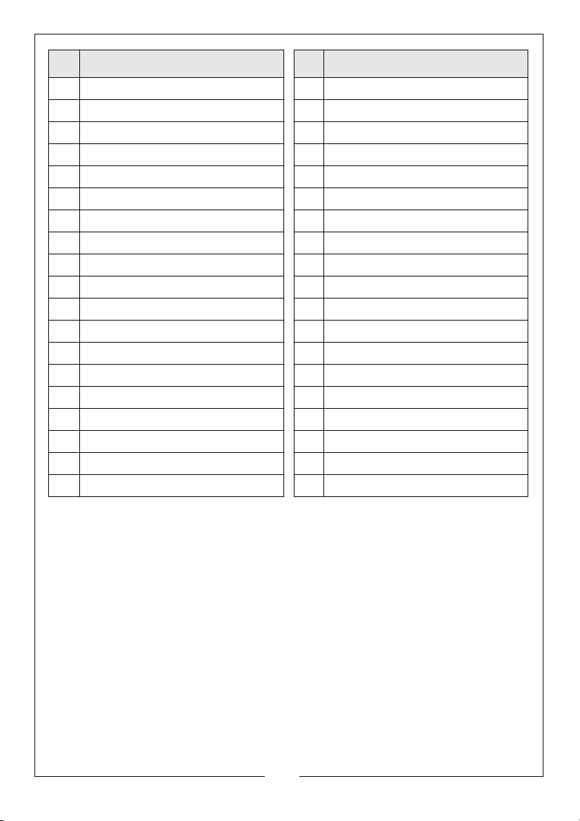
No Description No Description
57 Hook Assembly 76 Limit Switch
58 X-head Bolt 77 Terminal
59 Plastic Limit Piece 78 Switch Plate
60 Bolt 79 Junction Box Base
61 Bolt 80 Connecting Cable Sleeve
62 Spindle 81 Connecting Cable
63 Washer 82 Socket
64 Hook 83 Spade Connector
65 Pulley Wheel 84 Emergency Stop Button
66 Side Plate 85 Rocker Switch
67 Locknut 86 Pendant Casing - Front
68 Nut 87 Pendant Seal
69 Mains Plug 88 Adjusting Locknut
70 Limit Shaft 89 Switch Base
71 Waterproof Gland 90 Emergency Stop Switch
72 Plastic Closing Ring 91 X-Head Screw
73 Switch Connector 92 Pendant Casing - Rear
74 Cable Clamp 93 Capacitor
75 Junction Box Cover
15
Parts & Service: 020 8988 7400 / E-mail: [email protected] or [email protected]
Page 16
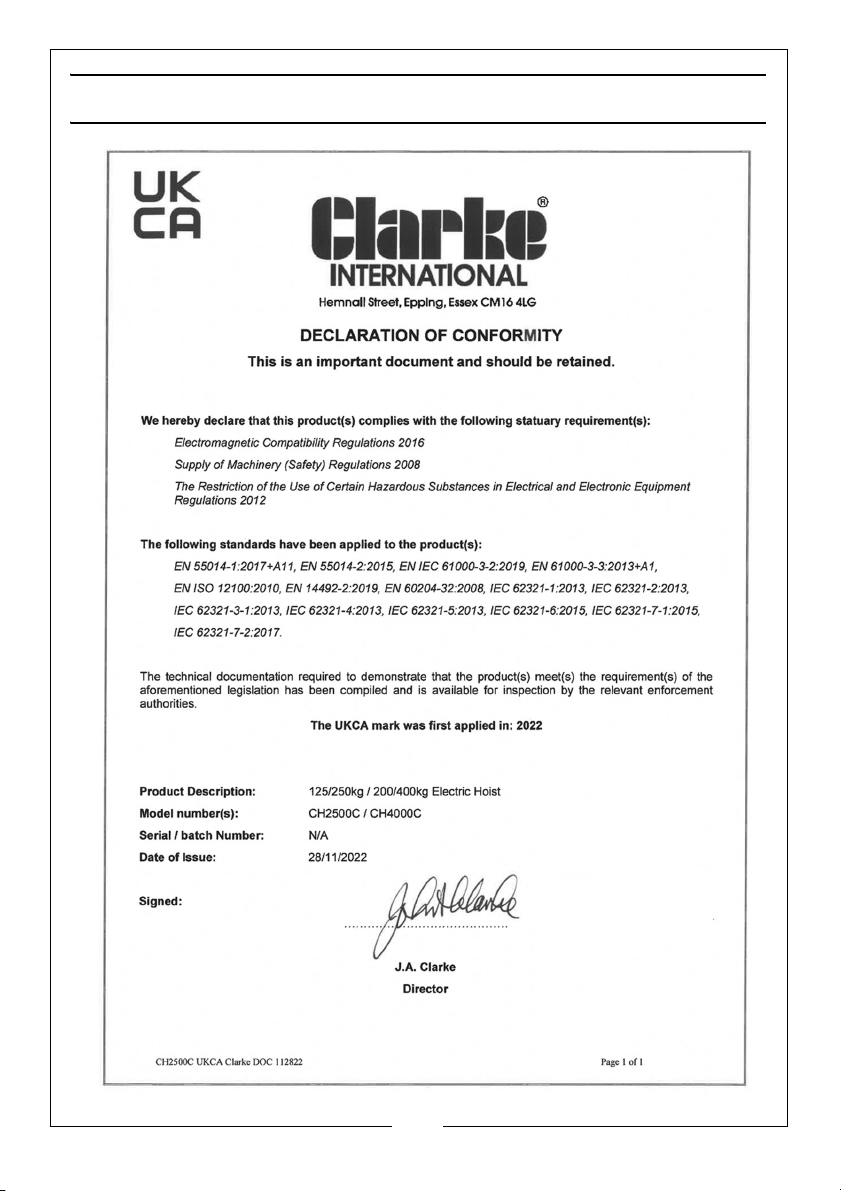
DECLARATIONS OF CONFORMITY - CH2500C
16
Parts & Service: 020 8988 7400 / E-mail: [email protected] or [email protected]
Page 17
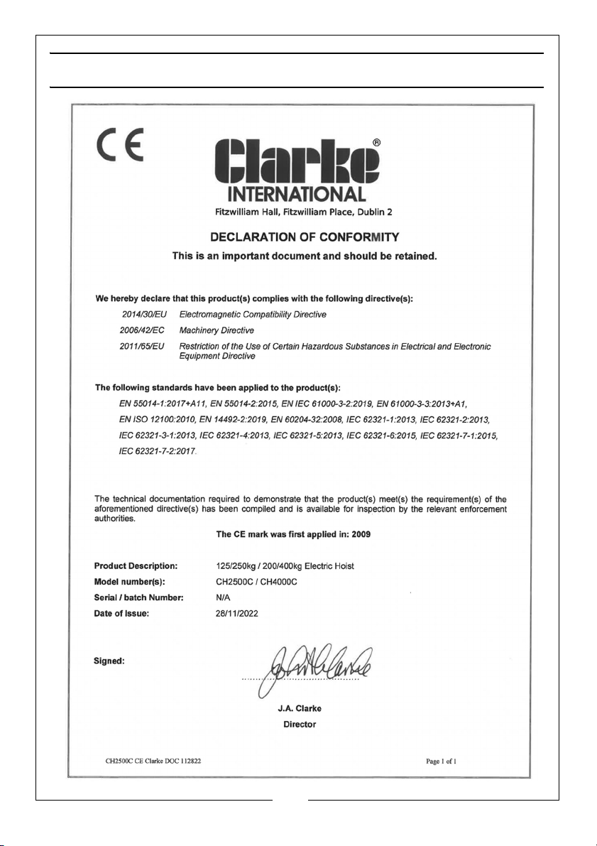
DECLARATIONS OF CONFORMITY - CH2500C
17
Parts & Service: 020 8988 7400 / E-mail: [email protected] or [email protected]
Page 18
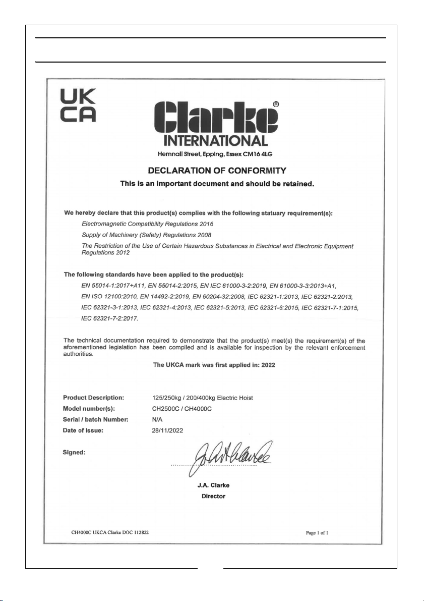
DECLARATIONS OF CONFORMITY - CH4000C
18
Parts & Service: 020 8988 7400 / E-mail: [email protected] or [email protected]
Page 19
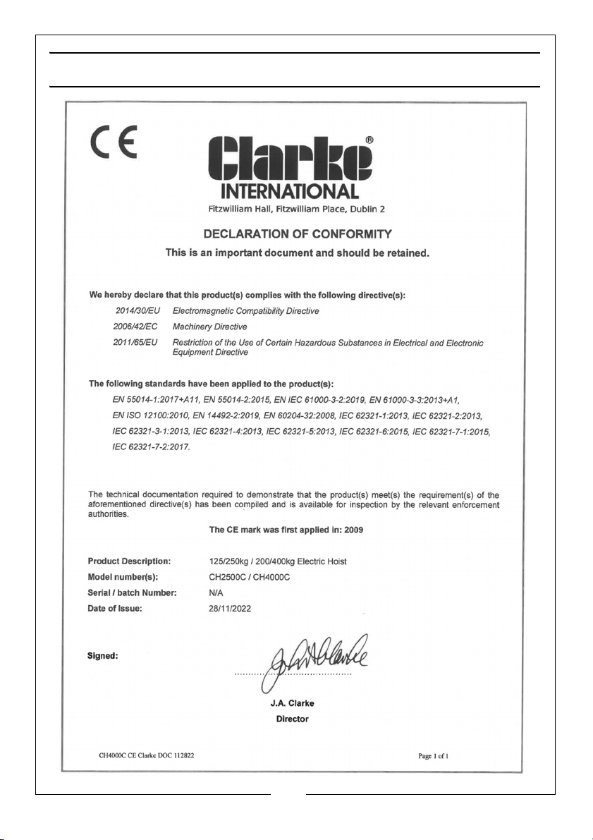
DECLARATIONS OF CONFORMITY - CH4000C
19
Parts & Service: 020 8988 7400 / E-mail: [email protected] or [email protected]
Page 20
 Loading...