

Page 1
WOODEN WORKBENCH
MODEL NO: CH1500B
PART NO: 6500129
ASSEMBLY INSTRUCTIONS
ORIGINAL INSTRUCTIONS GC 03-24
Page 2
INTRODUCTION
Thank you for purchasing this CLARKE product.
Please read these instructions carefully in order to ensure that the workbench
is assembled correctly, thereby ensuring that it provides you with long and
satisfactory service.
When unpacking, check for any damage that may have occurred in transit
and notify your CLARKE dealer immediately should any be apparent. Confirm
against the inventory on pages 4-6 that all items are present.
.
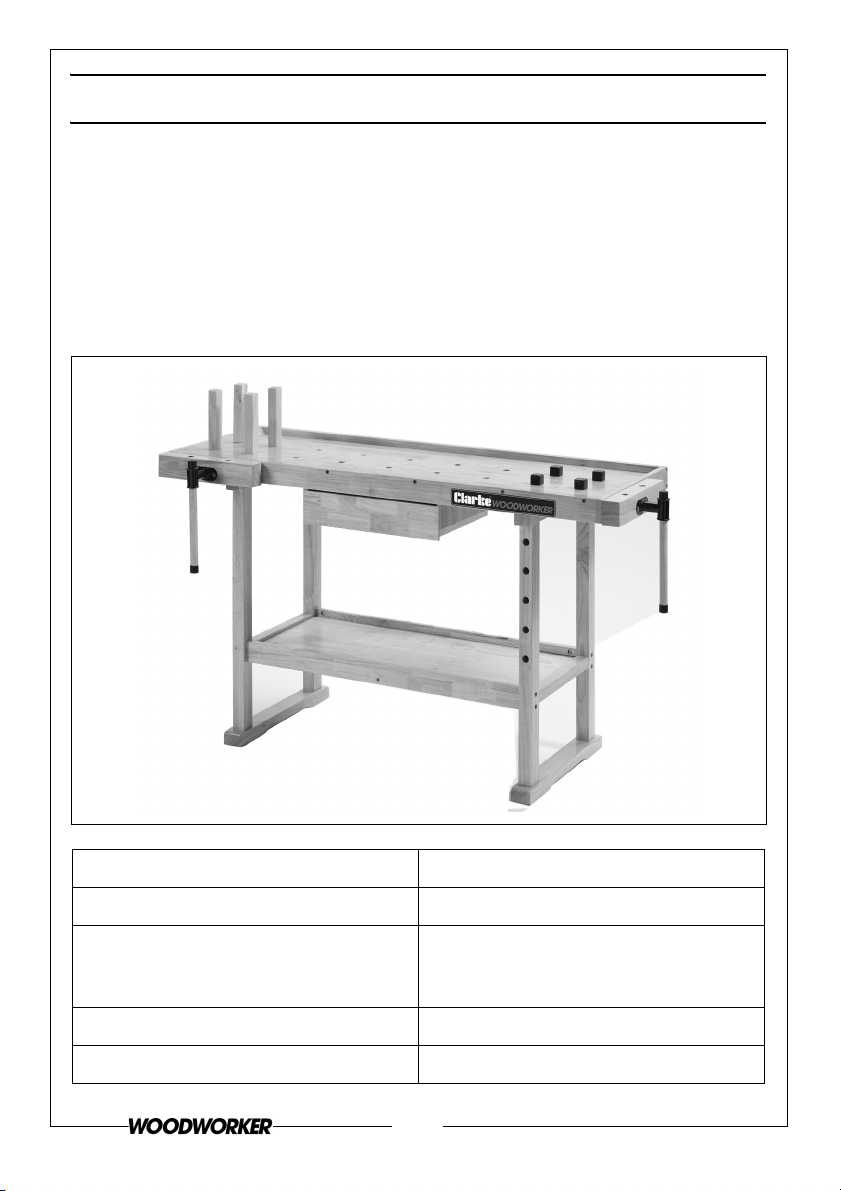
Product Dimensions (D x W x H) 640 x 1530 x 844 mm overall
Weight 30 kg
Weight loading Top bench - 200kg
Shelf - 100kg
Drawer - 10kg
Worktop dimensions 1400 x 510 mm
Drawer dimensions (H x W x D) 70 x 365 324mm
2
Parts & Service: 020 8988 7400 / E-mail: [email protected] or [email protected]
Page 3

GUARANTEE
This product is guaranteed against faulty manufacture for a period of 12
months from the date of purchase. Please keep your receipt which will be
required as proof of purchase.
This guarantee is invalid if the product is found to have been abused or
tampered with in any way, or not used for the purpose for which it was
intended.
Faulty goods should be returned to their place of purchase, no product can
be returned to us without prior permission.
This guarantee does not effect your statutory rights.
GENERAL SAFETY PRACTICES
1. Keep the work area clean and tidy.
2. Dress appropriately - Do not wear loose clothing or jewellery. Tie long hair
out of the way.
3. Keep children and visitors away - Do not let children handle the
components.
4. Do not overreach - Keep proper footing and balance at all times.
TOOLS REQUIRED
•Hex key (4mm)
• X-head screwdriver
•Standard screwdriver
3
Parts & Service: 020 8988 7400 / E-mail: [email protected] or [email protected]
Page 4
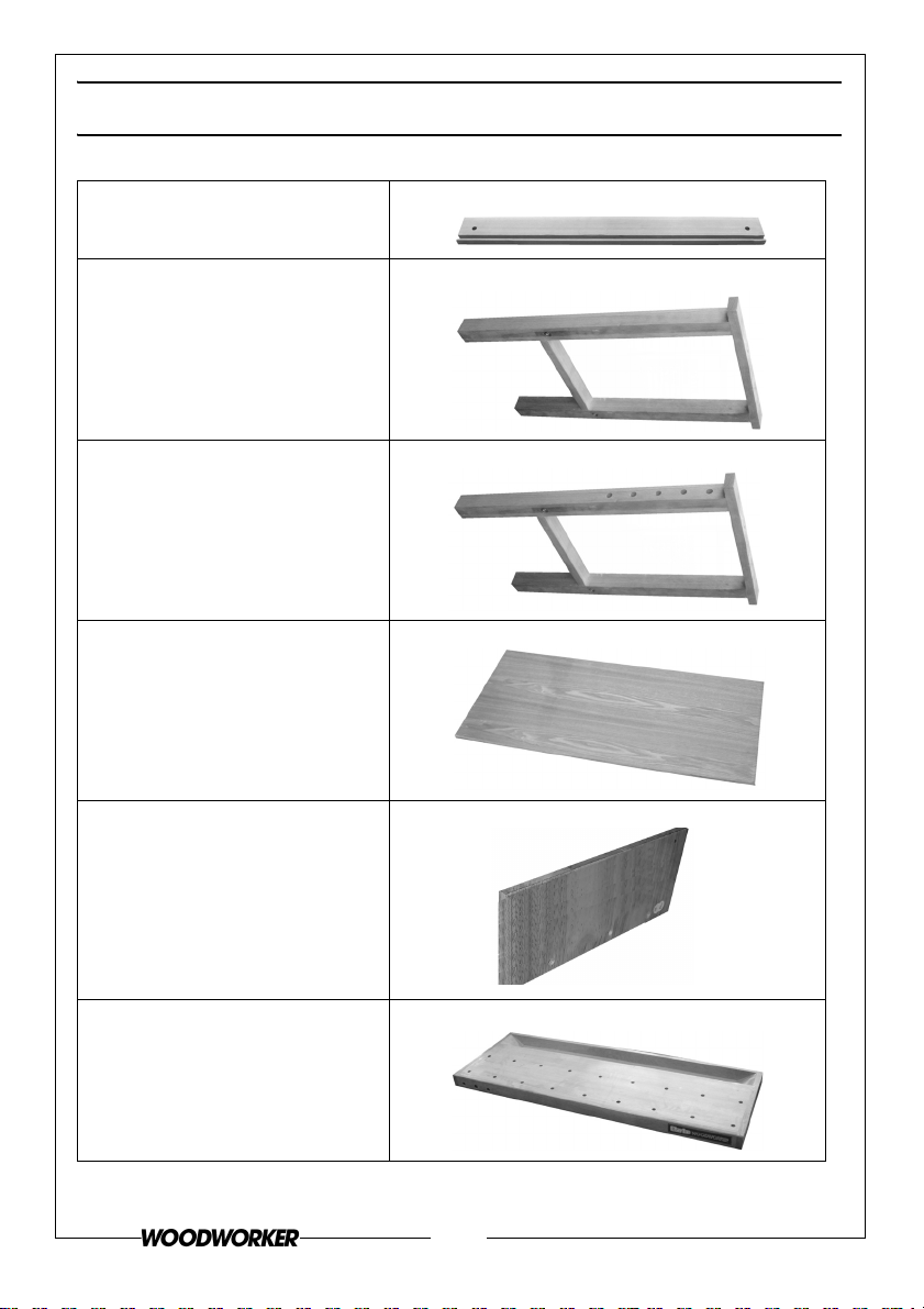
PACK CONTENTS
A) Side piece (pair)
B) Left leg frame
C) Right leg frame
D) Shelf base
E) Drawer holder (left and right
handed pair)
F) Worktop
4
Parts & Service: 020 8988 7400 / E-mail: [email protected] or [email protected]
Page 5
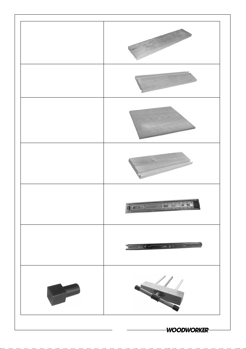
G) Drawer front
H) Drawer side
I) Drawer base
J) Drawer rear
K) Outer Drawer Runner(pair)
L) Inner Drawer Runner (pair)
M) Steel locating dog (x4) N) Woodworkers vice assembly(pair)
5
Parts & Service: 020 8988 7400 / E-mail: [email protected] or [email protected]
Page 6
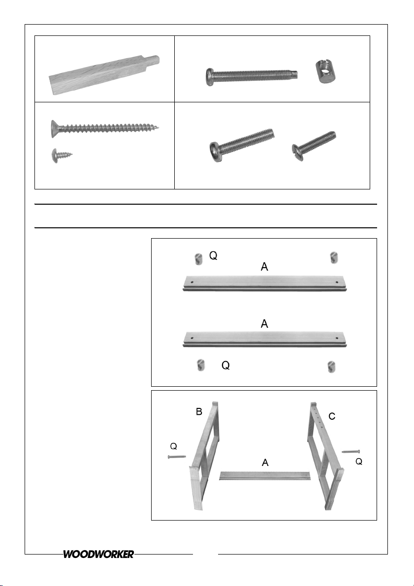
P) Workbench pegs (x 4) Q) Shelf machine screw & barrel nut s(x4)
R) Wood screw
(Long (x8)/Short) (x6)
ASSEMBLY
1. Insert the barrel nuts
(Q) into the side
pieces (A).
S) Machine screws (Long (x4)/Short (x4))
s
2. Use the machine
screws (Q) to secure
both leg frames (B
and C) to one of the
side pieces.
6
Parts & Service: 020 8988 7400 / E-mail: [email protected] or [email protected]
Page 7
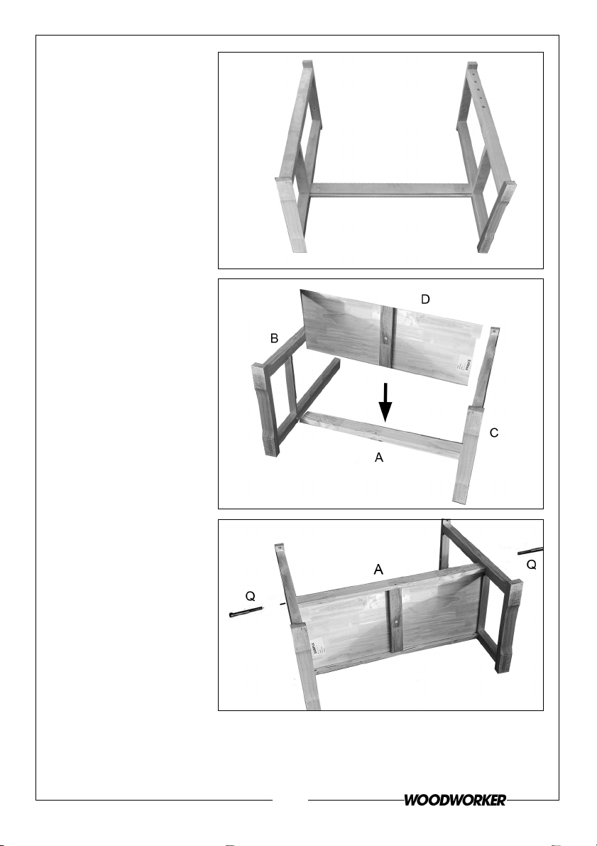
At this stage the frame
should look like this.
3. Slide the shelf base
(D) into the grooves
in the side pieces as
shown.
4. Secure the second
side piece to the
two leg frames using
machine screws (Q)
and barrel nuts.
7
Parts & Service: 020 8988 7400 / E-mail: [email protected] or [email protected]
Page 8
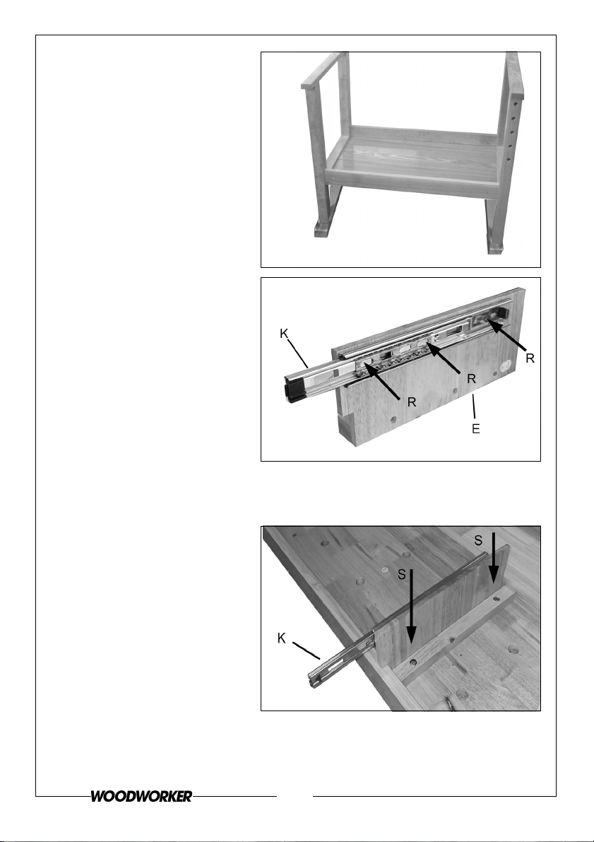
At this stage the frame should
look like this.
The outer drawer runners (K)
need to be fitted to both the
drawer holders (E).
• The inner runners (L) will
be fitted to the side
panels of the drawer.
Identify which runner is for the
drawer (inner) and which is for
the holders (outer). Ensure the
outer drawer runners are
screwed to the drawer holders
using the short wood screws
supplied. Slide the drawer runner left and right to access the fixing points.
5. Lay the workbench upside down.
6. Fix the drawer holders (E)
into place using the short
machine screws (S).
• The drawer holder
panels should be
labelled L and R.
8
Parts & Service: 020 8988 7400 / E-mail: [email protected] or [email protected]
Page 9
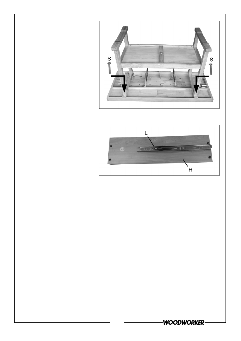
7. Fit the legs into position
and secure the assembly
using long machine
screws (S).
8. Turn the assembly the right way up.
9. Take the drawer side
panels (H) and
determine which is left
and right and therefore
which is the outside
surface of each panel.
10. Fix the inner draw
runners (L) to the inside
faces of the panels using
the short wood screws (R).
11. Assemble the drawer as follows.
9
Parts & Service: 020 8988 7400 / E-mail: [email protected] or [email protected]
Page 10
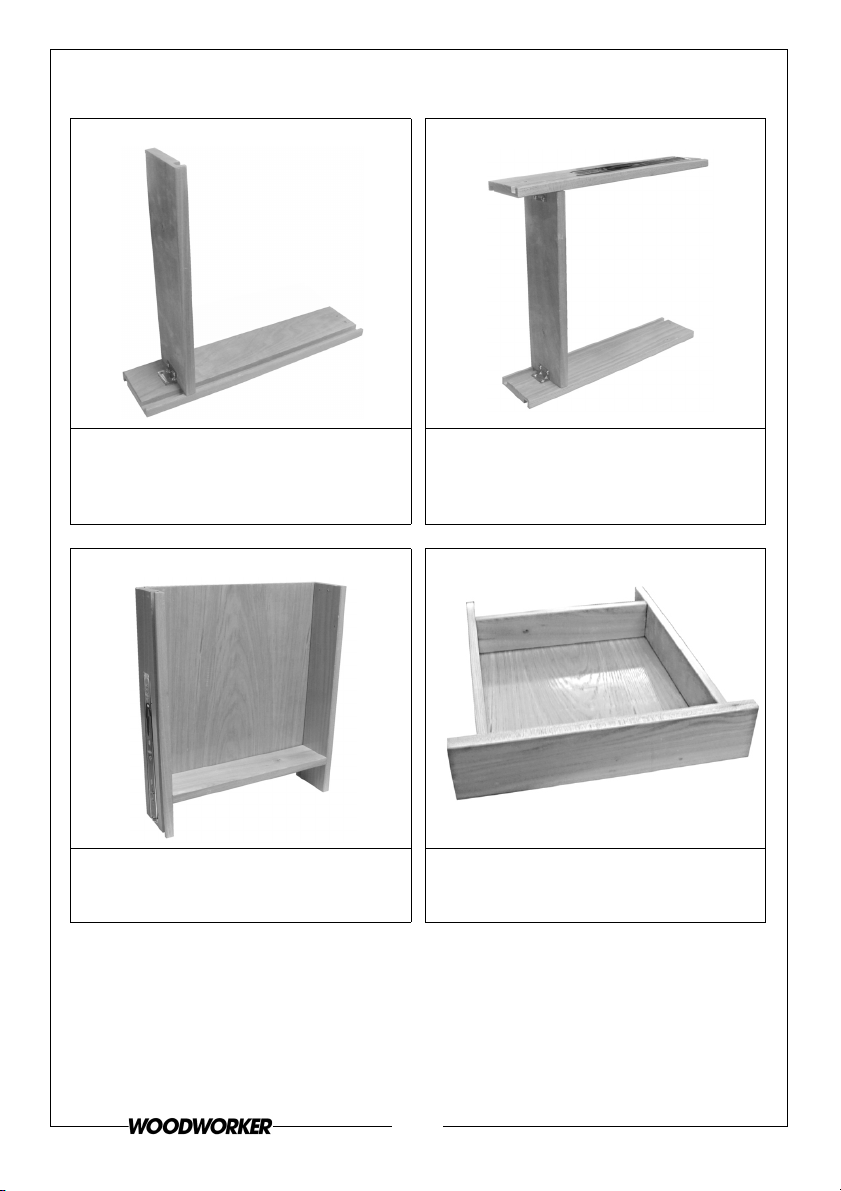
DRAWER ASSEMBLY
11.1 11.2
Fit the rear of the drawer (J) to one of
Fit the other side (H) as shown.
the drawer sides (H) and fix into
position using the long screws (R)
provided.
11.3
Rotate the drawer and slide the
drawer base (I) into position.
11.4
Fix the drawer front (G) as shown
above.
The drawer is now complete.
12. Slide the drawer along its runners until it clips into place.
• A plastic clip in each runner facilitates removal of the drawer in
future.
10
Parts & Service: 020 8988 7400 / E-mail: [email protected] or [email protected]
Page 11
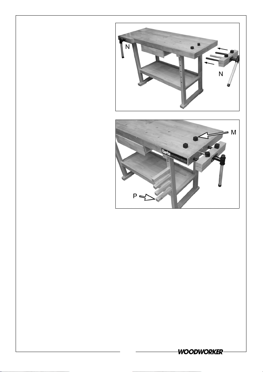
13. Fit both vice assemblies as
shown, inserting the guides
and screw thread into the
sockets in the bench and
screwing home as required.
14. Fit the locating pegs and
dogs into their locating
holes as required.
11
Parts & Service: 020 8988 7400 / E-mail: [email protected] or [email protected]
Page 12

 Loading...