

Page 1
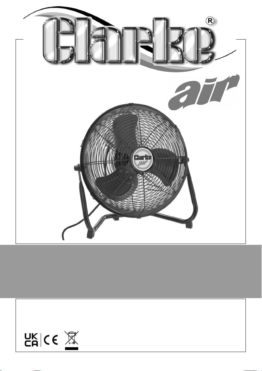
12 INCH FLOOR FAN
MODEL NO: CFF1250
PART NO: 3231545
OPERATION & MAINTENANCE
INSTRUCTIONS
ORIGINAL INSTRUCTIONS
GC04/24
Page 2
INTRODUCTION
Thank you for purchasing this CLARKE 12 inch Floor Fan.
Before attempting to use this product, please read this manual thoroughly and
follow the instructions carefully. In doing so you will ensure the safety of yourself
and that of others around you, and you can look forward to your purchase
giving you long and satisfactory service.
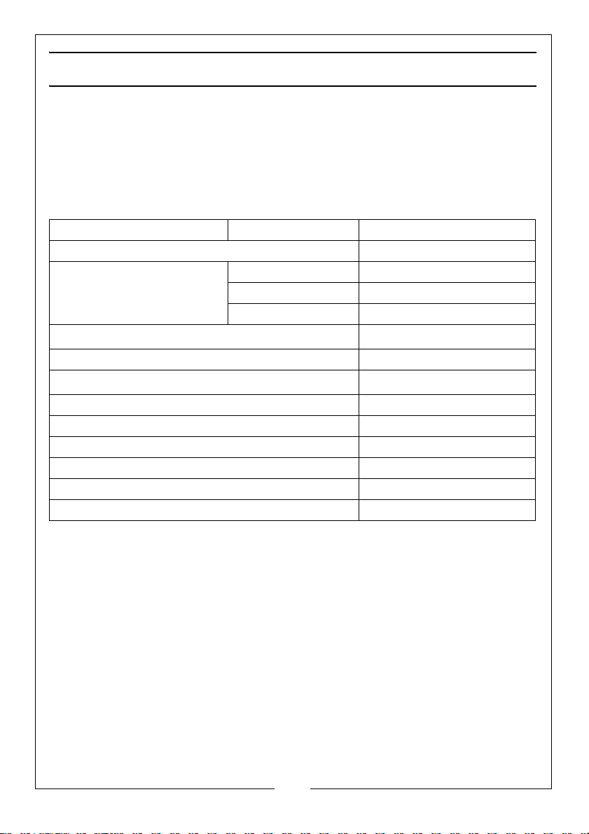
PRODUCT SPECIFICATIONS
Voltage 230 Vac ~ 50Hz
Fan Speeds 3
Setting 1 (Low) 1155 rpm
Setting 2 (Medium) 1250 rpm
Setting 3 (High) 1340 rpm
Maximum Airflow
Fan Power Input 45.8 W
Service Value
Measurement standard for service value 14.7 kWh/a
Ingress protection rating IPX0 (no water protection)
Sound Power level 56 dB(A)
Maximum Air Velocity 3.2 m/s
Dimensions (W x D x H) 390 x 170 x 400 mm
Weight 2.7 kg
47.7 (m
1.00 (m
3
/min)
3
/min) / (W)
GUARANTEE
This product is guaranteed against faulty manufacture for a period of 12
months from the date of purchase. Please keep your receipt which will be
required as proof of purchase.
This guarantee is invalid if the product is found to have been abused or
tampered with in any way, or not used for the purpose for which it was
intended.
Faulty goods should be returned to their place of purchase, no product can
be returned to us without prior permission.
This guarantee does not effect your statutory rights.
2
Parts & Service: 020 8988 7400 / E-mail: [email protected] or [email protected]
Page 3
ELECTRICAL CONNECTIONS
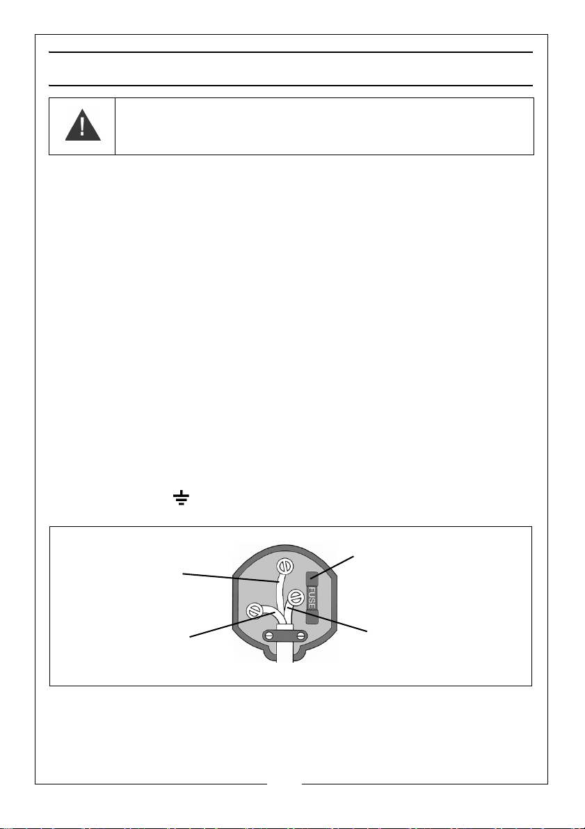
Plug must be BS1363/A approved.
Always fit a 3 Amp fuse.
Ensure that the outer sheath of the cable is firmly held by the clamp
Neutral
(Blue)
Live
(Brown)
Earth
(Green and Yellow)
WARNING: READ THESE ELECTRICAL SAFETY INSTRUCTIONS
THOROUGHLY BEFORE CONNECTING THE PRODUCT TO THE POWER
SUPPLY.
Before switching the product on, make sure that the voltage of your electricity
supply is the same as that indicated on the rating plate. This product is
designed to operate on 230VAC 50Hz. Connecting it to any other power
source may cause damage.
This product may be fitted with a non-rewireable plug. If it is necessary to
change the fuse in the plug, the fuse cover must be refitted. If the fuse cover
becomes lost or damaged, the plug must not be used until a suitable
replacement is obtained.
If the plug has to be changed because it is not suitable for your socket, or due
to damage, it should be cut off and a replacement fitted, following the wiring
instructions shown below. The old plug must be disposed of safely as insertion
into a mains socket could cause an electrical hazard.
If the colours of the wires in the power cable of this product do not correspond
with the markings on the terminals of your plug, proceed as follows.
•The Blue wire must be connected to the terminal marked N or
coloured Black.
•The Brown wire must be connected to the terminal marked L or
coloured Red.
•The Yellow and Green wire must be connected to the terminal
marked E or or coloured Green.
If in any doubt, consult a qualified electrician. DO NOT attempt any repairs
yourself.
Parts & Service: 020 8988 7400 / E-mail: [email protected] or [email protected]
3
Page 4
SAFETY PRECAUTIONS
• DO NOT use in dusty environments.
• DO NOT use in environments with high fumes from chemicals etc.
• DO NOT use as an extractor fan.
• DO NOT use in areas of high humidity/water vapour, i.e. bathrooms etc.
• DO NOT connect fan to ducting system.
• DO NOT cover the fan with clothing or any material that will restrict free
airflow through the fan
• NEVER touch the blades with your hand or any object.
• This product is for indoor use only.
OPERATION
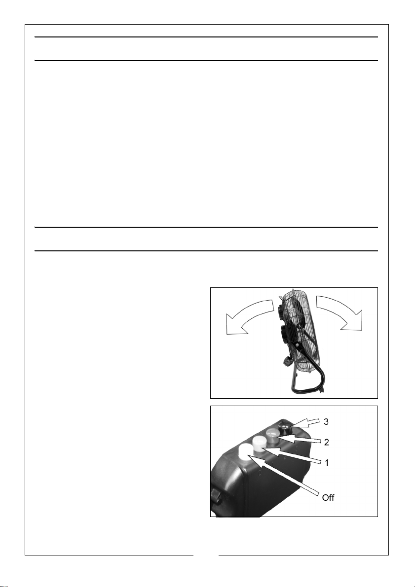
TILTING THE FAN
You can adjust the angle of the fan
by holding the base and grill and
tilting the fan to the required angle.
• Tighten the nuts on the side of
the fan slightly if the fan will not
stay in position
ADJUSTING THE SPEED
Press the relevant button to select the
fan speed required
• Button 0 - Off
• Button 1 - 1155 rpm
• Button 2 - 1250 rpm
• Button 3 - 1340 rpm
4
Parts & Service: 020 8988 7400 / E-mail: [email protected] or [email protected]
Page 5
MAINTENANCE
WARNING: NEVER OPERATE THE FAN WITH THE GUARDS REMOVED.
CLEANING
1. Unplug the power cable from the power supply.
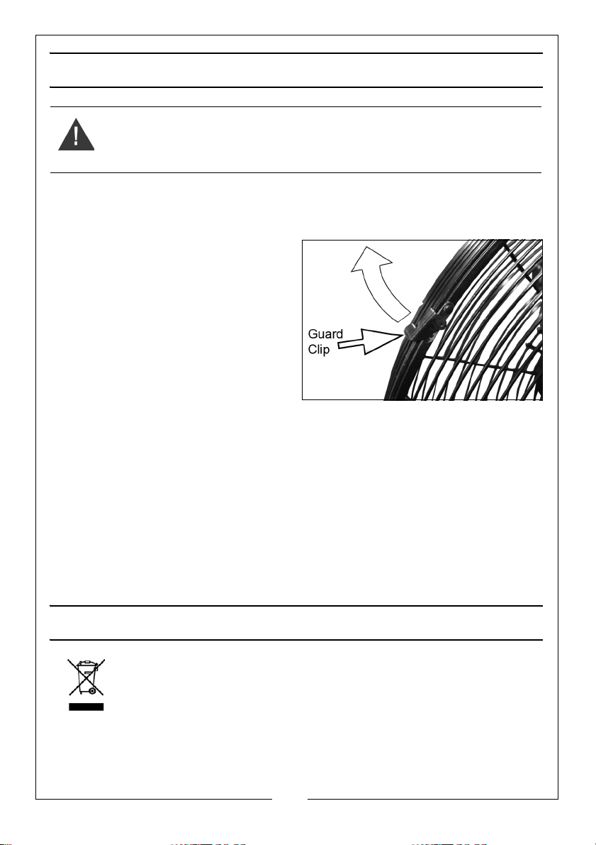
2. Lift the guard clips and remove
the single bolt and nut found at
the bottom of the guard.
3. Remove the guard carefully.
4. Wipe fan blades with a dry cloth.
• NEVER use polish or any
corrosive liquid that will
damage the finish.
• Take care not to bend the
blades.
5. Replace the guard so that the bolt holes in the front and rear guard line up
and lock the guard securely before use.
• Make sure that the guard clips are returned to the locked position.
GENERAL CARE
• The motor bearings are sealed for life and do not require any
additional lubrication.
• Have any repairs carried out by a suitably qualified person.
ENVIRONMENTAL RECYCLING POLICY
Through purchase of this product, the customer is taking on the
obligation to deal with the WEEE in accordance with the WEEE
regulations in relation to the treatment, recycling & recovery and
environmentally sound disposal of the WEEE.
In effect, this means that this product must not be disposed of with general
household waste. It must be disposed of according to the laws governing
Waste Electrical and Electronic Equipment (WEEE) at a recognised disposal
facility.
5
Parts & Service: 020 8988 7400 / E-mail: [email protected] or [email protected]
Page 6

COMPONENT PARTS
NO DESCRIPTION NO DESCRIPTION
1 Front guard with clips 11 Rubber cap
2 Fan blade assembly 12 Base frame
3 Set screw 13 Plastic foot
4. Motor 14 Screw
5X-head screw 15Power cable
6 Dome nut 16 Control switch box
7 Coach bolt 17 Screw
8 Rear guard 18 Washer
9 Plastic spacer 19 Handle grip
10 Locknut 20 Self tapping screw
6
Parts & Service: 020 8988 7400 / E-mail: [email protected] or [email protected]
Page 7
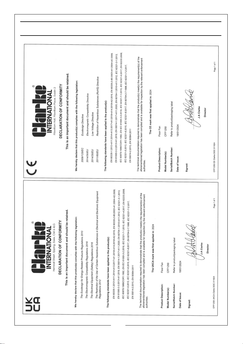
DECLARATION OF CONFORMITY
7
Parts & Service: 020 8988 7400 / E-mail: [email protected] or [email protected]
Page 8

 Loading...