

Page 1
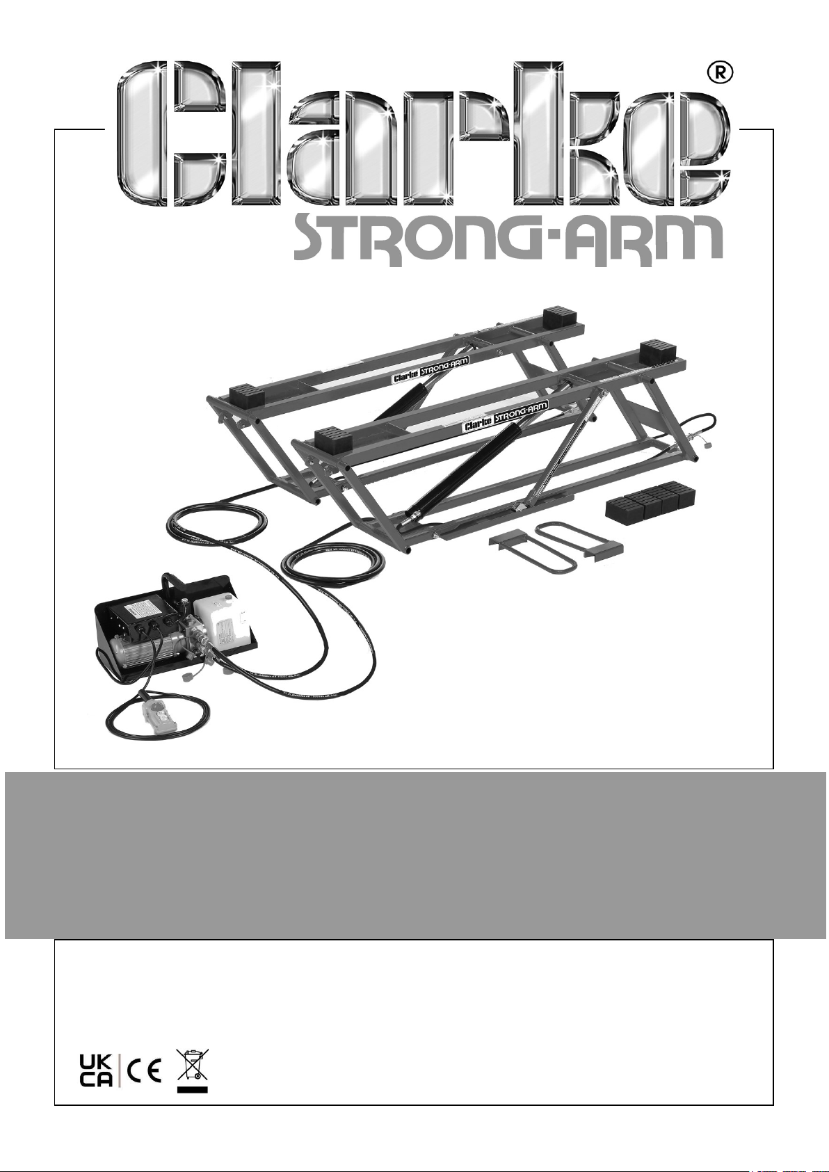
HYDRAULIC CAR LIFT
MODEL NO: CCL2250
PART NO: 7610146
OPERATION & MAINTENANCE
INSTRUCTIONS
ORIGINAL INSTRUCTIONS DL-04/25 - Rev 2
Page 2
INTRODUCTION
Thank you for purchasing this CLARKE Car Lift. Before attempting to operate this
product, it is essential that you read this manual thoroughly and carefully follow all
instructions given. In doing so you can look forward to the product giving you long
and satisfactory service.
SPECIFICATIONS
Model Number CCL2250
Rated voltage 230V - 50Hz
Current 5.5A
Ingress protection rating IP55
Maximum Safe Load 2268 kg
Minimum Table Height 75 mm
Maximum Frame Height 434 mm
Maximum Lifting Height 440/470mm
Net lifter weight 36.5 kg
Net pump unit weight (excluding hoses) 19.6 kg
Table dimensions 1770 x 280 x 80mm
Operating temperature range
Hydraulic fluid volume 2 L
Hydraulic fluid type ISO-15
Pump max working pressure 23Mpa/3335psi
Hydraulic hose length (each) 3810mm
-20oC - +50oC
GUARANTEE
This CLARKE product is guaranteed against faulty manufacture for a period of 12
months from the date of purchase. Please keep your receipt as proof of purchase.
This guarantee is invalid if the product is found to have been abused or tampered
with in any way, or not used for the purpose for which it was intended.
Faulty goods should be returned to their place of purchase, no product can be
returned to us without prior permission.
This guarantee does not effect your statutory rights.
2
Parts & Service: 020 8988 7400 / E-mail: [email protected] or [email protected]
Page 3
GENERAL SAFETY RULES
CAUTION: FAILURE TO FOLLOW THESE PRECAUTIONS COULD RESULT IN
PERSONAL INJURY, AND/OR DAMAGE TO PROPERTY.
LIFTING OPERATIONS AND LIFTING EQUIPMENT REGULA-
TIONS 1998
This lift may fall within the scope of LOLER. It is the owner’s responsibility to
determine whether or not it does and, if so, to comply with any applicable
requirements in LOLER, for having the lift thoroughly examined.
WORK ENVIRONMENT
1. Keep the work area clean, tidy and well lit. Cluttered and dark areas invite
accidents.
2. DO NOT operate in explosive atmospheres such as in the presence of flammable
liquids, gases or dust. Powered products create sparks which may ignite the dust
or fumes.
3. Keep children and bystanders away while operating this equipment. Distractions
can cause you to lose control.
4. NEVER leave this lift unattended whilst there is a load on it unless it is
mechanically locked using the safety bars fitted.
5. ALWAYS use the lift on a solid, flat, level surface capable of supporting the
weight of the lift and vehicle.
PERSONAL SAFETY
1. ENSURE the operator is trained in both operational and safety aspects of using
this product.
2. Stay alert, watch what you are doing and use common sense when operating a
lift. DO NOT use while you are tired or under the influence of drugs, alcohol or
medication. A moment of inattention may result in personal injury.
3. DO NOT overreach. Keep proper footing and balance at all times.
4. Dress properly. DO NOT wear loose clothing or jewellery. Keep your hair, clothing
and gloves away from moving parts. Loose clothes, jewellery or long hair can be
caught in moving parts.
5. ALWAYS use appropriate safety equipment when using this lift.
3
Parts & Service: 020 8988 7400 / E-mail: [email protected] or [email protected]
Page 4

ELECTRICAL SAFETY
1. Power plugs must match the outlet. NEVER modify the plug in any way. DO NOT
use adapter plugs with earthed (grounded) power products. Correct plugs and
matching outlets will reduce the risk of electric shock.
2. DO NOT abuse the cable. Keep the cable away from heat, oil, sharp edges or
moving parts. Damaged or entangled cables increase the risk of electric shock.
3. The power pack is protected to IP55 standards but outdoor use in all weathers
is not recommended.
4. If operating outdoors, use an extension cable suitable for outdoor use. Use of a
cable suitable for outdoor use reduces the risk of electric shock.
TABLE LIFT-SPECIFIC SAFETY PRECAUTIONS
1. ALWAYS inspect the lift before use to ensure it is in good condition and replace
any damaged or worn parts.
2. NEVER exceed the safe working load and only use the lift for its intended
purpose.
3. NEVER use the lift if it has been subjected to an abnormal load or shock. It
should be removed from service immediately and fully inspected by qualified
personnel before being passed as serviceable before being used again.
4. NEVER rely on the hydraulic rams to support the lifting tables when loaded.
5. NEVER crawl or reach under either lifting table unless mechanically locked using
the safety bars fitted.
6. ALWAYS use the locking bars to hold the tables in one of the positions provided.
7. NEVER raise a load directly on the frames. Always use the rubber lift blocks
provided.
8. All hose couplings must be securely connected before using the equipment and
never be disconnected during use due to the stored hydraulic pressure in the
hoses.
9. Ensure that the vehicle is equally balanced on the lift. If the vehicle to be lifted is
not correctly positioned there is a risk of it falling which could cause serious
personal injury and/or damage to property.
10. Before lifting, check that the lifting frames are correctly positioned under the
vehicle and as parallel as possible, that nobody is partly under the vehicle being
lifted, that the lifting frame ‘safety locking bars’ are turned outwards and that
there are no obstructions around or above the vehicle.
11. Familiarise yourself with the lift and its controls by raising and lowering it a few
times without a load. DO NOT raise to the maximum height without a load – only
raise it to the lower locking position.
12. DO NOT lower the vehicle if wheels or tyres have been removed. There must be
space between the ground and the load that is to be lifted, in order to raise the
4
Parts & Service: 020 8988 7400 / E-mail: [email protected] or [email protected]
Page 5

lifting frames slightly before lifting the load. The lift cannot lift a full load from a
fully lowered position.
13. For optimum load stability, always place the two lifting frames as parallel with
each other as the vehicle’s lifting points permit.
14. NEVER attempt to drive the vehicle up onto the lift as this will damage the lifting
frames.
15. ALWAYS keep clear of pinch points when the components are moving.
16. NEVER leave the lift unattended if it is not fully lowered or locked in the lower or
upper locking position. Scissor lifts are designed to only hold loads with the
locking bars in the safety locking positions.
17. ALWAYS use spare parts supplied by CLARKE International. Using non-standard
parts could be extremely dangerous.
Please keep these instructions in a safe place for future reference.
ENVIRONMENTAL PROTECTION
DO NOT dispose of this product with general household waste. All tools, accessories
and packaging should be sorted, taken to a recycling centre and disposed of
according to the laws governing Waste Electrical and Electronic Equipment.
Through the purchase of this product, the customer is taking on the obligation to deal
with the WEEE in accordance with the WEEE regulations in relation to the treatment,
recycling & recovery and environmentally sound disposal of the WEEE.
In effect, this means that this product must not be disposed of with general
household waste. It must be disposed of according to the laws governing Waste
Electrical and Electronic Equipment (WEEE) at a recognised disposal facility.
5
Parts & Service: 020 8988 7400 / E-mail: [email protected] or [email protected]
Page 6
ELECTRICAL CONNECTIONS
WARNING! READ THESE ELECTRICAL SAFETY INSTRUCTIONS
THOROUGHLY BEFORE CONNECTING THE MACHINE TO THE
MAINS SUPPLY.
Before switching the product on, make sure that the voltage of your electricity supply
is the same as that indicated on the rating plate. This product is designed to operate
on 230VAC 50Hz. Connecting it to any other power source may cause damage.
This product may be fitted with a non-rewireable plug. If it is necessary to change the
fuse in the plug, the fuse cover must be refitted. If the fuse cover becomes lost or
damaged, the plug must not be used until a suitable replacement is obtained.
If the plug has to be changed because it is not suitable for your socket, or due to
damage, it should be cut off and a replacement fitted, following the wiring
instructions shown below. The old plug must be disposed of safely, as insertion into a
mains socket could cause an electrical hazard.
If the colours of the wires in the power cable of this product do not correspond with
the markings on the terminals of your plug, proceed as follows.
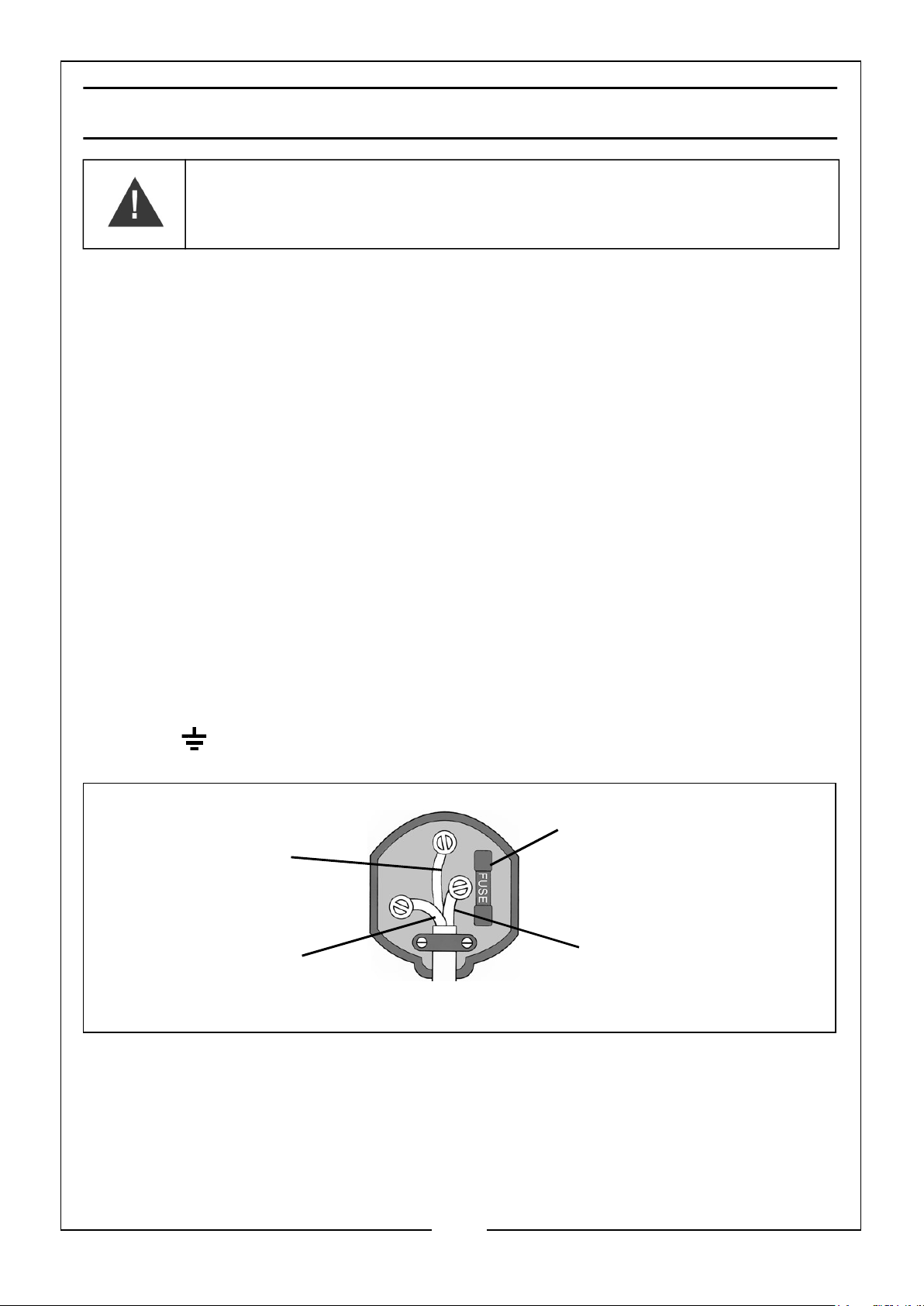
• The Blue wire must be connected to the terminal marked N or coloured
Black.
• The Brown wire must be connected to the terminal marked L or coloured
Red.
• The Yellow and Green wire must be connected to the terminal marked E
or or coloured Green.
Plug must be BS1363/A approved.
Always fit a 13 Amp fuse.
Earth
(Green and Yellow)
Neutral
(Blue)
Ensure that the outer sheath of the cable is firmly held by the clamp
Live
(Brown)
We strongly recommend that this machine is connected to the mains supply via a
Residual Current Device (RCD). If in any doubt, consult a qualified electrician. DO
NOT attempt any repairs yourself.
6
Parts & Service: 020 8988 7400 / E-mail: [email protected] or [email protected]
Page 7
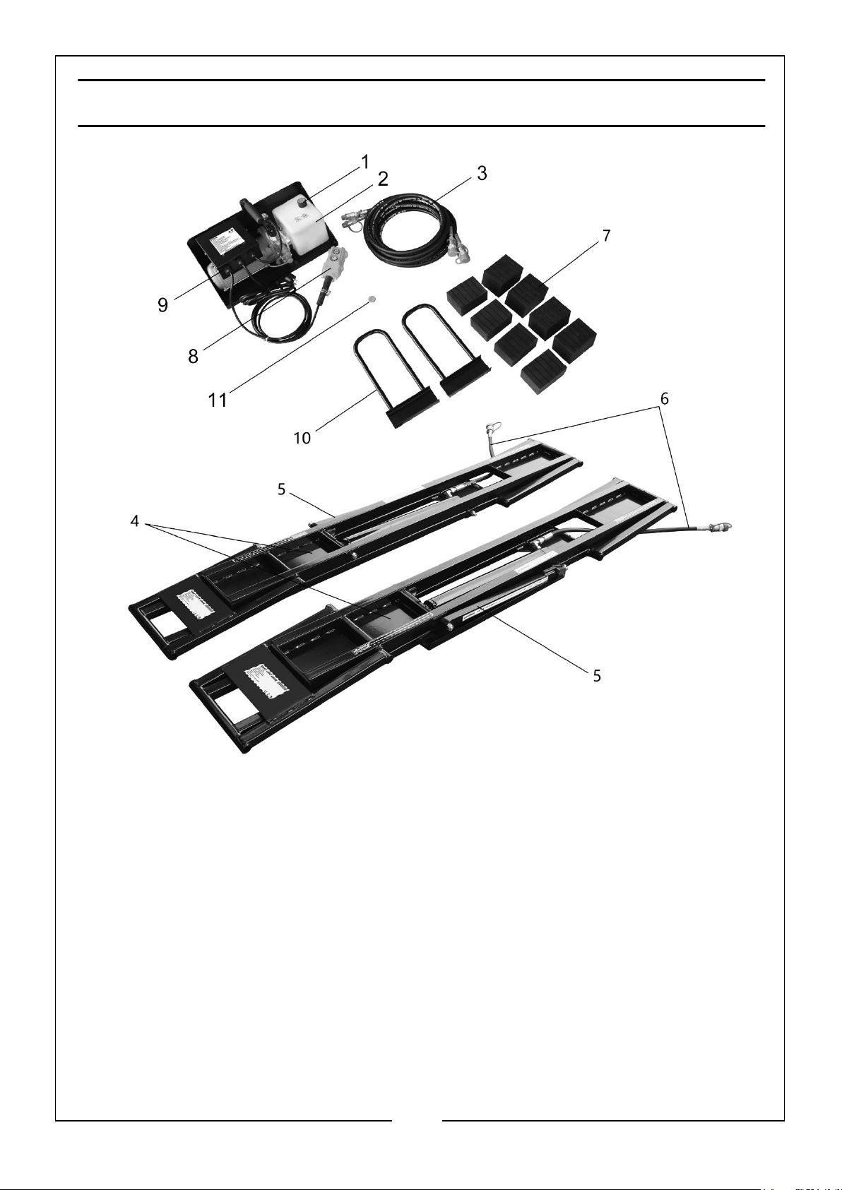
OVERVIEW & INVENTORY
1. Filler plug for hydraulic fluid
2. Hydraulic fluid reservoir
3. Long hydraulic hoses with couplers (x2)
4. Lifting frames (x2)
5. Safety lock bar (x2)
6. Short hydraulic hoses with couplers (x2)
7. Rubber lifting blocks 55mm (X4) and 75mm (x4)
8. Remote control
9. Hydraulic power unit
10. Positioning handles
11. Sealing plug for hydraulic reservoir
7
Parts & Service: 020 8988 7400 / E-mail: [email protected] or [email protected]
Page 8
UNPACKING
WARNING: DUE TO THE WEIGHT OF THE COMPONENTS IT IS
ADVISED THAT TWO PEOPLE PERFORM THE UNPACKING.
Unpack the components and remove packing materials. Check to ensure that no
damage has occurred during transit. Before proceeding, please check contents
against the inventory list and immediately advise the CLARKE dealer where you
purchased the product if any parts are missing. Refer also to the inventory on page 7.
ASSEMBLY & PREPARATION
Unpack the equipment, laying out the loose items using a clean, level area.
NOTE: On delivery, there will be no hydraulic fluid in the fluid reservoir of the
power unit. Fill with hydraulic fluid before using the product.
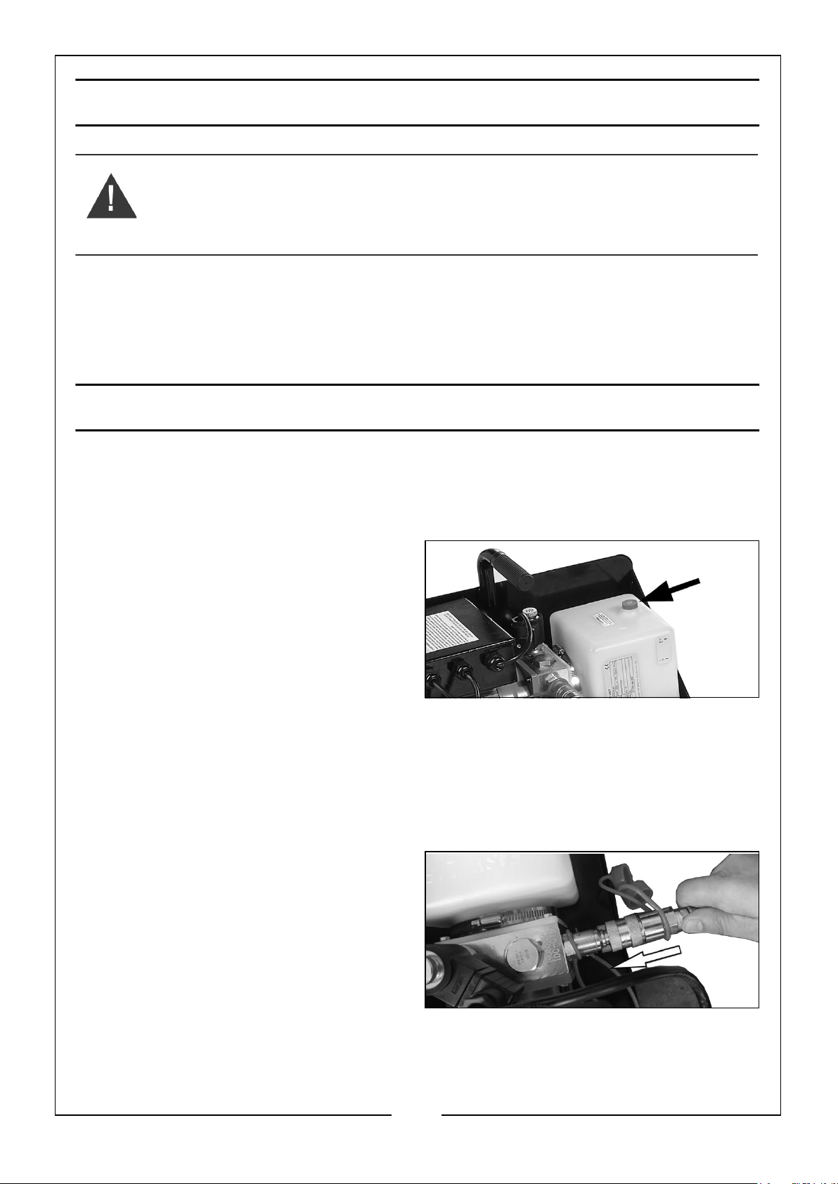
1. Unscrew the filler plug (1) and fill
with 2 litres of hydraulic oil (ISO 15,
ISO 46 or HP 32) in the fluid reservoir
(2). Screw the plug back on.
NOTE: HP 32 Hydraulic Oil can be
purchased from your local
CLARKE dealer.
• CLARKE 1 litre HP 32 Hydraulic Oil, Part No: 3050830
• CLARKE 5 litre HP 32 Hydraulic Oil, Part No: 3050835
NOTE: Hydraulic fluids should NOT be mixed under any circumstances, i.e
using 2 litres of HP 32, then subsequently topping up with another fluid
(e.g. ISO 15), needs to be avoided.
2. Connect the female couplers on the
long hose (3) to the male couplers on
the hydraulic power unit (9).
8
Parts & Service: 020 8988 7400 / E-mail: [email protected] or [email protected]
Page 9
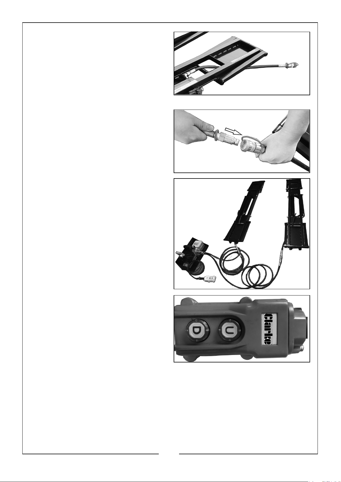
3. Route the short hose (6) under the
bottom of the lifting frames (4),
never over the lifting frames.
4. Connect the male couplers on the
long hoses to the female couplers on
the short hose.
5. Connect the power unit to the power
supply.
• The lift is now ready to use.
6. Press the U button (up) on the
remote control (8) to lift and the D
button (Down) to lower.
NOTE: Do not raise to maximum
height without a load.
BLEEDING
Air may accumulate within the hydraulic system after connecting the hoses causing
erratic movement during operation. Raising and lowering the lift few time should
purge the air from the system, giving smooth movement.
9
Parts & Service: 020 8988 7400 / E-mail: [email protected] or [email protected]
Page 10

OPERATION AND LIFTING PROCEDURE
POSITIONING THE LIFTING FRAMES
IMPORTANT:
• Before positioning the lifting frames, check that both frames are fully lowered
and that the work area is free from obstacles.
• Check that the vehicle is well balanced and cannot tip in any direction.
• Never lift a load directly on the lifting frames – always use the lifting blocks.
The lifting frames can be positioned under the vehicle either from the outside or the
inside.
Avoid driving over the hydraulic hoses.
WARNING: DO NOT DRIVE THE VEHICLE ONTO THE LIFTING FRAMES.
FROM THE OUTSIDE
1. Park the vehicle in the desired location and align the lifting frames between the
wheels along the vehicle’s sides. If the distance between the wheels is too short
for there to be room for the lifting frames, turn the lifting frames and first push in
one end and then the other.
2. Check that the safety lock bars are facing out.
3. Move the lifting frames to the desired positions under the vehicle.
FROM THE INSIDE
1. Position the lifting frames beside each other. Check that the safety lock bars are
facing out.
2. Move the vehicle forward so that the lifting frames are midway under the vehicle.
Avoid driving over the hydraulic hoses.
3. Move the lifting frames to the desired location under the vehicle’s lifting points.
The lifting handles can be used for this.
POSITIONING THE LIFTING FRAMES UNDER THE VEHICLE
IMPORTANT:
1. Determine the desired method for placing the lifting frames under the vehicle.
2. Place lifting blocks of the same thickness on the lifting frame plates.
3. Position the lifting frames in a suitable place in relation to the lifting points on the
vehicle.
10
Parts & Service: 020 8988 7400 / E-mail: [email protected] or [email protected]
Page 11
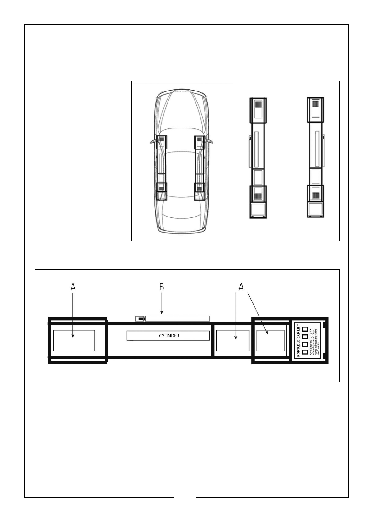
4. Adjust the lifting blocks on the plates so that they are directly beneath the
vehicle’s lifting points.
• In this way, the lifting frames and lifting blocks are correctly positioned to lift
the vehicle.
IMPORTANT: The
lifting frames must
be in parallel under
the vehicle.
LIFTING BLOCKS
NEVER raise a load directly on the frames. Always use the rubber lift blocks provided.
Position them in each of the trays on the platforms.
A. Storage tray for the lifting blocks.
B. Safety lock bar, (must be on outside).
SAFETY LOCKING BARS
On each lifting frame there is a lock bar that is used to lock the frame in the required
position.
11
Parts & Service: 020 8988 7400 / E-mail: [email protected] or [email protected]
Page 12
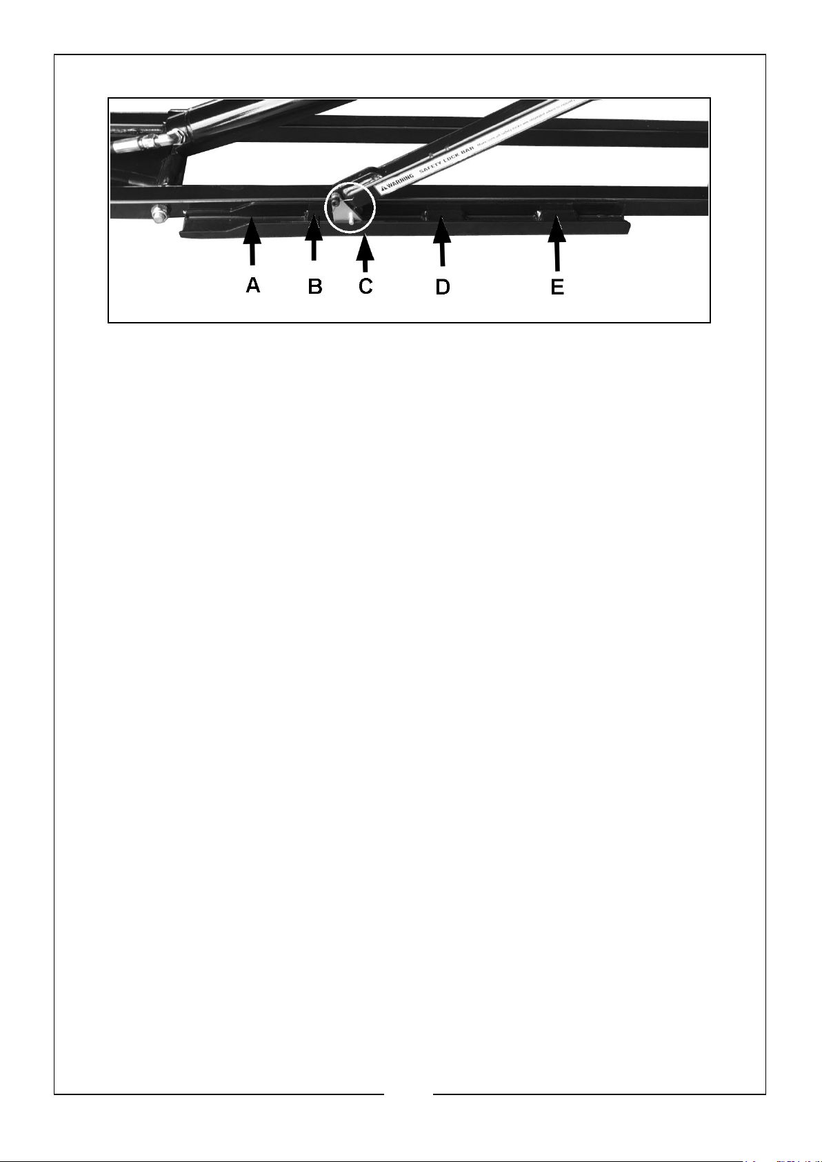
This lift has three locking positions:
• A. Tracks.
• B. Lower Locking Position.
• C. The Turning Block MUST remain in the tracks.
• D. Middle Locking Position.
• E. Upper Locking Position.
DO NOT leave the lift unattended if is not fully lowered or locked in one of the three
locked positions. Always check before use that the locking bars can move easily and
remain in their tracks.
The product will not work correctly if the locking bars have become stuck in the upper
position or are not located in their tracks.
LIFTING
1. Before raising the lift, check to ensure the vehicle is stable, ensuring there is
nothing to obstruct the lift.
2. Press and hold the U button on the remote control. The lifting frames will raise.
3. Release the U button just before the lifting block comes into contact with the
vehicle’s lifting points. The lifting frames will stop moving. Check that the rubber
lifting blocks are correctly aligned in relation to the vehicle’s lifting points. Adjust
the rubber lifting blocks if necessary.
• The vehicle may need to be lowered slightly in order for the rubber lifting
blocks to be able to be moved.
4. Press the U button on the remote control again to continue lifting.
WARNING: DO NOT STOP LIFTING UNTIL THE LIFTING FRAMES HAVE
PASSED THE LOWER LOCKING POSITION.
5. Release the U button to stop lifting immediately after the lower locking position,
even if you are going to continue lifting to the upper locking position.
12
Parts & Service: 020 8988 7400 / E-mail: [email protected] or [email protected]
Page 13
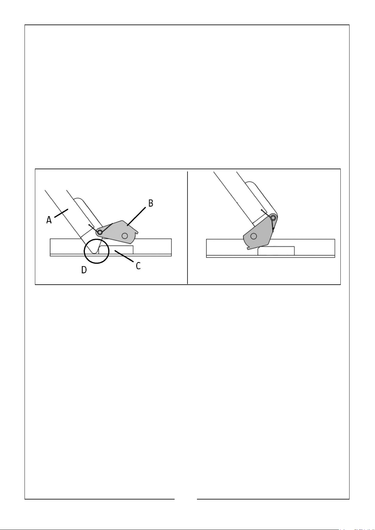
6. Check that the lifting blocks are located at the vehicle’s lifting points. If the lifting
blocks are correctly positioned, continue lifting. If the lifting blocks are not
correctly positioned, press the D button on the remote control to lower the vehicle
and make the necessary adjustments.
7. Check that the vehicle is correctly balanced. If it is, continue lifting. If the vehicle
is not correctly balanced, press the D button on the remote control to lower the
vehicle and make the necessary adjustments.
8. Lift the vehicle a little way past the desired locking position (lower or upper).
9. Release the U button and press the D button to lower the vehicle to the locking
position. The lowering of the lifting frames is interrupted by locking.
10. Check that both lifting frames have been locked at the same locking position.
A. Locking bar
B. Turning block
C. Locking block
D. Locked position
WARNING: BEFORE STARTING WORK ON THE VEHICLE OR LEAVING THE
AREA, CHECK VISUALLY THAT BOTH THE LIFTING FRAMES ARE LOCKED IN
THE SAME LOCKING POSITION AND THAT ALL THE LIFTING BLOCKS ARE IN
CONTACT WITH THE VEHICLE’S LIFTING POINTS. WORK ON THE VEHICLE
CAN BE PERFORMED WHEN BOTH THE LIFTING FRAMES ARE LOCKED IN THE
SAME LOCKING POSITION AND ALL THE LIFTING BLOCKS ARE IN CONTACT
WITH THE VEHICLE’S LIFTING POINTS. NEVER WORK OR SPEND TIME
UNDER A RAISED VEHICLE THAT IS NOT SUPPORTED AT THE LIFTING
POINTS WITH APPROVED SUPPORTS.
13
Parts & Service: 020 8988 7400 / E-mail: [email protected] or [email protected]
Page 14

LOWERING THE FRAMES FROM THE LOCKED POSITION
WARNING: WHEN LOWERING THE FRAMES, MAKE SURE THE LOCKING BAR
AND THE TURNING BLOCK STAY IN THEIR TRACKS. IF THEY GET KNOCKED
SIDEWAYS, FOR EXAMPLE, THEY CAN GET STUCK ON THE RAIL OF THE
TRACK WHICH COULD RESULT IN THE LIFT NOT LOWERING CORRECTLY.
1. Press the UP button until the locking bar is clear of the locking block.
2. Lift the locking bar on both frames so that the turning block is on top of the
locking block on both frames, You can use a tool to lift the locking bar.
3. Press the D(own) button on the remote control. Make sure the locking bar is clear
of the locking block on both frames on their way down. Release the DOWN button
if either side does not clear the locking block.
4. Continue pressing the D(own) button until both frames are lowered to the ground.
NOTE: Press and hold the D(own) button for a few seconds after the lifting
frames have been fully lowered in order to return as much hydraulic
fluid as possible to the reservoir.
5. Remove the frames from underneath the vehicle.
• You may want to use the frame handles.
6. Move the vehicle as required. Take care not to drive the vehicle over the frames or
the hydraulic hoses.
14
Parts & Service: 020 8988 7400 / E-mail: [email protected] or [email protected]
Page 15
MAINTENANCE
WARNING: ISOLATE THE POWER SUPPLY AND RELIEVE THE HYDRAULIC
PRESSURE PRIOR TO ANY MAINTENANCE AND/OR CLEANING. Relieve
pressure by holding the D button for a few seconds after the lifting frames have been
fully lowered, in order to return as much hydraulic fluid to the fluid reservoir.
CHECKS BEFORE USE
• Check all bolted joints regularly and tighten them if necessary.
• Check the frames for cracks in weld joints as well as damaged, loose, worn or
missing parts before use. DO NOT use the lift until any worn or damaged parts
have been replaced.
• Check that the safety lock bars are in good condition and working properly. DO
NOT use if the safety lock bars are damaged.
• Check the lifting blocks and replace them if they are damaged.
MONTHLY (IF IN CONSTANT USE)
Carry out the following maintenance every month.
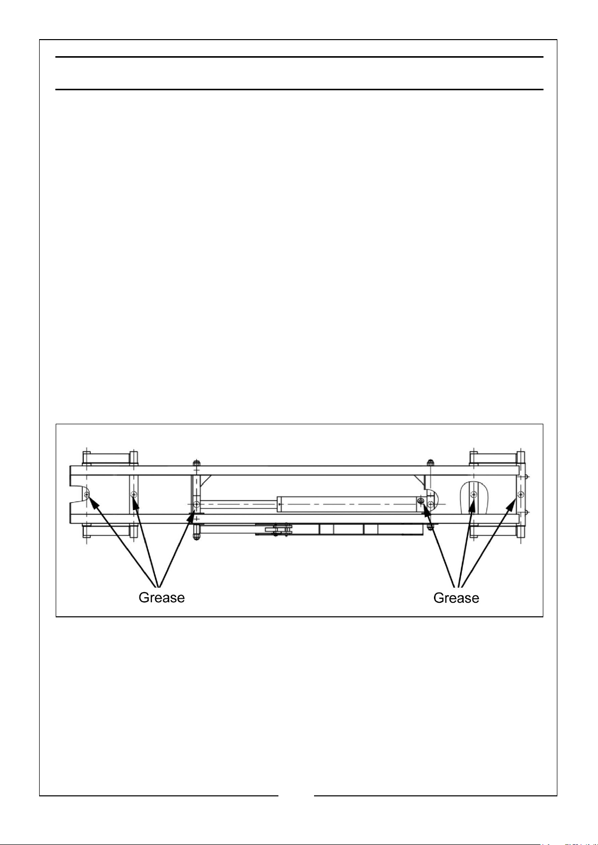
1. Lubricate all joints and check for wear. If necessary, lubricate with white lithium
grease or equivalent using a grease gun at the locations shown.
2. Check the hydraulic fluid level and top up if necessary.
3. Check that the safety and warning labels on the product are intact and legible.
Replace any that are illegible or missing.
CLEANING
Keep all parts clean for optimum functionality and service life.
• Use suitable personal protective equipment when working with the hydraulic
system.
15
Parts & Service: 020 8988 7400 / E-mail: [email protected] or [email protected]
Page 16

• Avoid skin contact with hydraulic fluid. Follow the manufacturer's safety
instructions.
Contact a doctor immediately in the event of swallowing of hydraulic fluid.
MOVING AND STORAGE
If you need to transport the hydraulic power unit any distance, replace the filler plug
on the fluid reservoir with the sealing plug.
• The filler plug cannot seal the fluid into the reservoir effectively allowing
possible spillage during transportation.
If you need to transport the power unit a long distance, empty the fluid before
dispatch. DO NOT use sealing plug when you are using the power unit as it will cause
an airlock.
If the lift is to be moved, release the long hydraulic hoses from the power unit and
move the pump, Move the lifting frames with hoses separately.
Store the lift fully lowered when not in use.
REPAIRS
Contact your CLARKE dealer for technical assistance or repairs. The warranty will be
invalidated if the product is damaged as a result of an accident, negligence or
incorrect use, or if it has been repaired by unauthorised personnel.
WARNING: ANY REPAIRS MUST BE CARRIED OUT BY AN AUTHORISED
SERVICE CENTRE OR OTHER QUALIFIED PERSONNEL.
ENVIRONMENTAL PROTECTION
One of the most damaging sources of environmental pollution is oil products. NEVER
throw away used hydraulic oil with domestic refuse or flush it down a sink or drain.
Collect any hydraulic oil in a leak proof container and take it to your local waste
disposal site.
If disposing of this product or any damaged components, do not dispose of with
general waste. This product contains valuable raw materials and should be taken to
your local civic amenity site for recycling of metal products.
16
Parts & Service: 020 8988 7400 / E-mail: [email protected] or [email protected]
Page 17
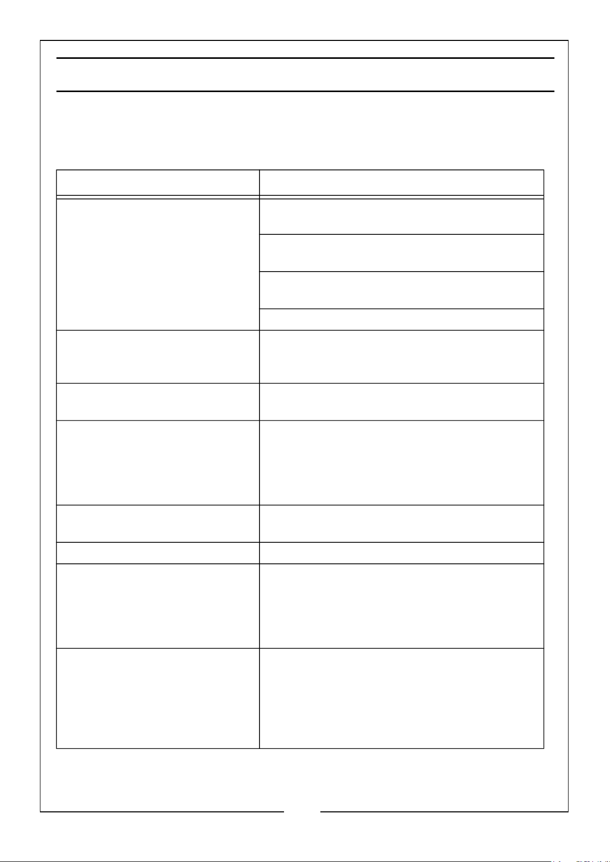
TROUBLESHOOTING
The troubleshooting guide may identify common problems and suggestions as to how
they can be rectified. Contact your dealer if you experience a problem that is not
included in this guide.
PROBLEM SUGGESTED ACTION
Lifting frames cannot be raised or
lowered
Lifting frames cannot be lowered Confirm that there is a load on the frames. If
The power unit fails to deliver any
pressure
Lifting frames cannot be raised
from a fully lowered position
Check the hydraulic hoses are not bent,
clenched or leaking
Check the level of the hydraulic fluid in the
reservoir.
Check that the power unit has the correct power
supply
Bleed the hydraulic cylinders
not, place a load on them. (the product is
designed to operate with a load in position.
Send the power unit for repair or contact your
CLARKE dealer.
There must be space between the ground and
the load that is to be lifted in order to raise the
lifting frames slightly before lifting the load. The
lift cannot lift a full load from a fully lowered
position.
Contaminated hydraulic fluid. Replace with new fluid of the correct type listed
on page 2.
Abnormal noise during use. Lubricate the joints with lithium grease
Lifting frames sink slowly without
any buttons being pressed.
Couplings are difficult to connect Residual pressure in hydraulic systems. Relieve
Parts & Service: 020 8988 7400 / E-mail: [email protected] or [email protected]
Check the safety locking bars are locked in one
of the locking positions.
Otherwise, hydraulic fluid could be leaking under
pressure. Do not leave unattended if not fully
lowered or locked in one of the three positions.
any pressure by holding the D button for a few
seconds after the lifting frames have been fully
lowered, in order to return as much hydraulic
fluid to the fluid reservoir. If the pressure is too
high contact your CLARKE dealer.
17
Page 18
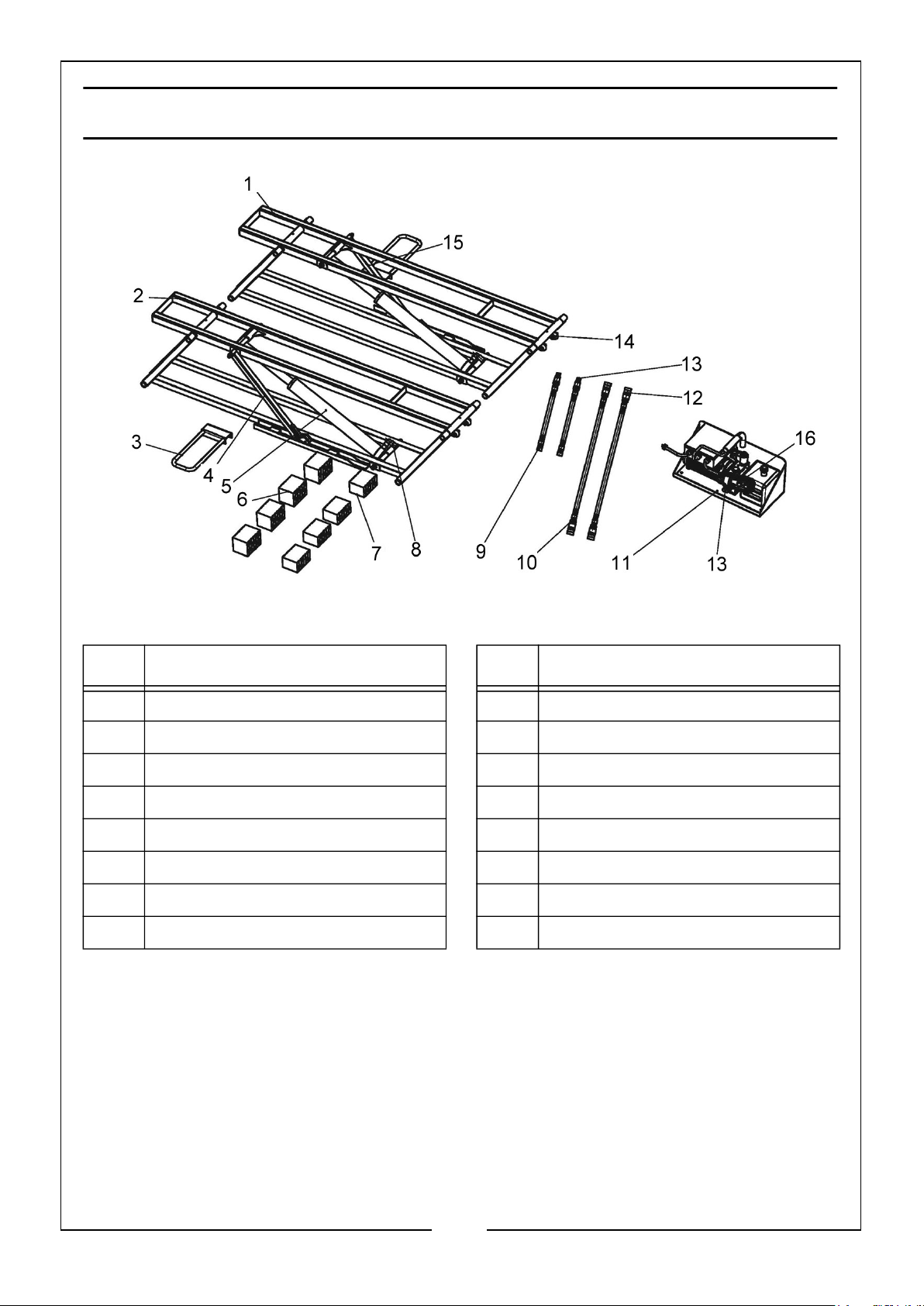
COMPONENT PARTS
ITEM DESCRIPTION ITEM DESCRIPTION
1 Lift frame A 9 Short hose
2 Lift frame B 10 Long hose
3 Frame handle 11 Power unit
4 Locking bar A 12 Female coupler
5 Hydraulic cylinder 13 Male coupler
6 Rubber lift blocks (3”) 14 Wheel
7 Rubber lift blocks (2”) 15 Locking bar B
8 Fitting 16 Controller assembly
18
Parts & Service: 020 8988 7400 / E-mail: [email protected] or [email protected]
Page 19
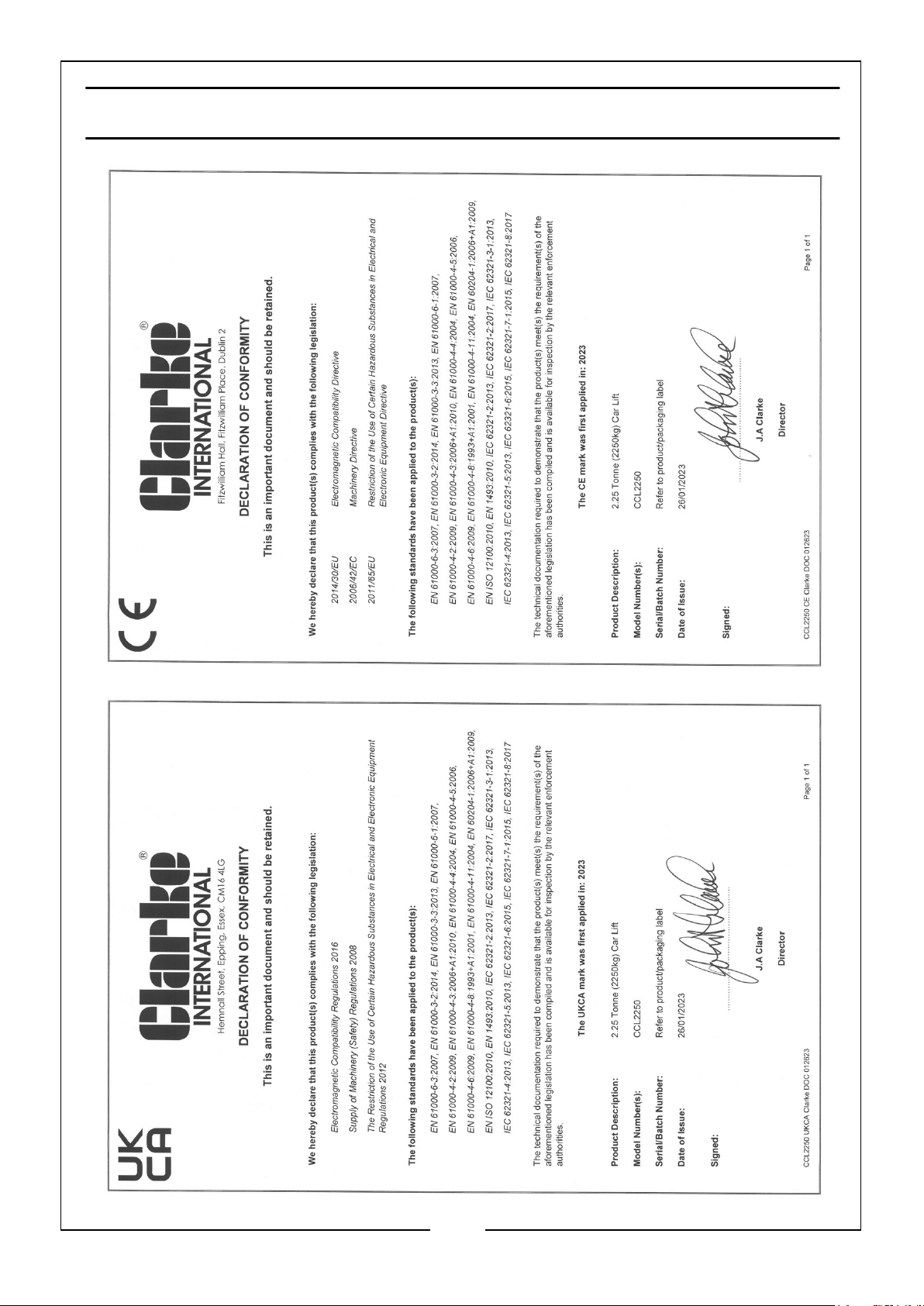
DECLARATIONS OF CONFORMITY
19
Parts & Service: 020 8988 7400 / E-mail: [email protected] or [email protected]
Page 20
 Loading...