

Page 1
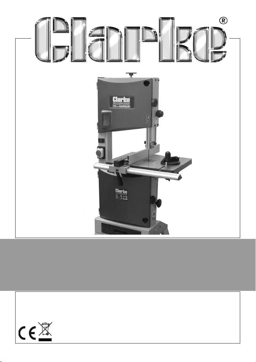
BANDSAW
MODEL NO: CBS300/CBS350
PART NO: 6460077 / 6460078
OPERATION & MAINTENANCE
INSTRUCTIONS
ORIGINAL INSTRUCTIONS GC1020 - ISS 4
Page 2
INTRODUCTION
Thank you for purchasing this CLARKE Bandsaw.
Before attempting to operate the machine, it is essential that you read this
manual thoroughly and carefully follow all instructions given. In doing so you
will ensure the safety of yourself and that of others around you, and you can
also look forward to the product giving you long and satisfactory service.
GUARANTEE
This CLARKE product is guaranteed against faulty manufacture for a period of
12 months from the date of purchase. Please keep your receipt as proof of
purchase.
This guarantee is invalid if the product is found to have been abused or
tampered with in any way, or not used for the purpose for which it was
intended.
Faulty goods should be returned to their place of purchase, no product can
be returned to us without prior permission.
This guarantee does not effect your statutory rights.
ENVIRONMENTAL PROTECTION
Recycle unwanted materials instead of disposing of them as waste. All
unwanted accessories and packaging should be sorted and taken to a
recycling centre for disposal in a manner which is compatible with the
environment.
ENVIRONMENTAL RECYCLING POLICY
Through purchase of this product, the customer is taking on the
obligation to deal with the WEEE in accordance with the WEEE
regulations in relation to the treatment, recycling & recovery and
environmentally sound disposal of the WEEE.
In effect, this means that this product must not be disposed of with general
household waste but according to the laws governing Waste Electrical and
Electronic Equipment (WEEE) at a recognised disposal facility.
2
Parts & Service: 020 8988 7400 / E-mail: [email protected] or [email protected]
Page 3
SAFETY WARNINGS
CAUTION: FAILURE TO FOLLOW THESE PRECAUTIONS COULD RESULT IN
PERSONAL INJURY, AND/OR DAMAGE TO PROPERTY.
WORK ENVIRONMENT
1. Keep the work area clean and well lit. Cluttered and dark areas invite
accidents.
2. Do not operate power tools in explosive atmospheres, such as in the
presence of flammable liquids, gases or dust. Power tools create sparks
which may ignite the dust or fumes.
3. Keep children and bystanders away while operating a power tool. Anyone
entering the work area must wear personal protective equipment.
Distractions can cause you to lose control and fragments of work or a
broken disc may fly away and cause injury.
4. Store power tools properly when not in use. Abrasive products should be
stored in a dry, secure place out of the reach of children.
5. Please read these instructions carefully and retain for future reference.
ELECTRICAL SAFETY
1. Power tool plugs must match the outlet. Never modify the plug in any way.
Do not use adapter plugs with earthed (grounded) power tools. Unmodified
plugs and matching outlets will reduce the risk of electric shock.
2. Do not expose power tools to rain or wet conditions. Water entering a
power tool will increase the risk of electric shock.
3. Do not abuse the cord. Never use the cable for carrying, pulling or
unplugging the power tool. Keep the cable away from heat, oil, sharp
edges or moving parts. Damaged or entangled cables increase the risk of
electric shock.
4. When operating a power tool outdoors, use an extension cable suitable for
outdoor use. Use of a cable suitable for outdoor use reduces the risk of
electric shock.
PERSONAL SAFETY
1. Stay alert, watch what you are doing and use common sense when
operating a power tool. Do not use a power tool while you are tired or
under the influence of drugs, alcohol or medication. A moment of
inattention while operating power tools may result in personal injury.
3
Parts & Service: 020 8988 7400 / E-mail: [email protected] or [email protected]
Page 4

2. Use personal protective equipment. Always wear eye protection. Safety
equipment such as dust mask, non-skid safety shoes, hearing protection
and a workshop apron capable of stopping small abrasive or workpiece
fragments.
3. Avoid accidental starting. Ensure the switch is in the off position before
plugging in. Plugging in power tools that have the switch on invites
accidents.
4. Remove any adjusting key or wrench before turning the power tool on. A
wrench or a key left attached to a rotating part of the power tool may
result in personal injury.
5. Do not overreach. Keep proper footing and balance at all times. This
enables better control of the power tool in unexpected situations. Dress
properly. Do not wear loose clothing or jewellery.
6. Keep your hair, clothing and gloves away from moving parts. Loose
clothes, jewellery or long hair can be caught in moving parts. Keep the
work area clean and tidy.
7. Regularly clean the power tool’s air vents. The motor fan will draw dust
inside the housing and accumulation of material could cause electrical
hazards.
8. Avoid operator fatigue. Stop the power tool at regular intervals for a short
break to rest hands and arms.
9. Maintain your tools. Keep all handles and grips dry and clean.
ELECTRICAL SAFETY
1. Position the power cable so that it cannot be inadvertently pulled or
pinched, and where it does not cause a trip hazard.
2. This machine is designed for indoor environments and must not be used for
other purposes.
3. If the machine requires repair, always contact your Clarke dealer. Always
insist on original spare parts. Repairs carried out by unauthorized persons
may be dangerous and invalidate the guarantee.
4. This machine must only be used by adults. Children should not be allowed
to play with this appliance.
5. Do not use extension power cables.
6. Before cleaning or maintenance operations, always unplug the machine
from the power supply.
POWER TOOL USE AND CARE
1. Do not force the machine. Use the correct power tool for your application.
It will do a better and safer job at the rate for which it was designed.
4
Parts & Service: 020 8988 7400 / E-mail: [email protected] or [email protected]
Page 5

2. Do not use the power tool if the switch does not turn it on and off. Any
power tool that cannot be controlled with the switch is dangerous and
must be repaired.
3. Disconnect the power tool from the power supply before making any
adjustments, changing accessories, or storing the tool. These measures will
reduce the risk of the power tool starting accidently.
4. Store power tools out of the reach of children and do not allow persons
unfamiliar with these instructions to operate the power tool. Power tools are
potentially dangerous in the hands of untrained users.
5. Maintain power tools in top condition. Keep tools/ machines clean for the
best and safest performance. Check for misalignment or binding of
moving parts, broken parts, or any condition that may affect the power
tool’s operation. If damaged, have the power tool repaired before use.
Many accidents are caused by poorly maintained power tools.
6. Use recommended accessories. The use of improper accessories could be
hazardous.
7. Machine cleanliness. Do not allow the ventilation slots in the machine to
become blocked with dust.
8. Check the power tool for damage before using the machine. Any
damaged part should be inspected to ensure that it will operate properly
and perform its intended function. Check for alignment of moving parts,
breakage of parts, mountings, and any other condition that may affect the
machine’s operation. Any damage should be properly repaired or the part
replaced. If in doubt, DO NOT use the machine. Consult your local dealer.
SERVICING
1. When necessary, have your power tools serviced or repaired by a qualified
person using identical replacement parts. This will ensure that the safety of
the power tool is maintained.
ADDITIONAL PRECAUTIONS FOR BANDSAWS
1. Always check safety guards are in place and functioning correctly before
switching the machine on.
2. Always use a push stick, especially on small workpieces.
3. Always use the appropriate saw blade for the material being cut.
4. Never use the machine if the electric cable or plug is in poor condition.
5. Never allow the ventilation slots in the motor to become blocked.
6. Never touch the blade immediately after use, when changing the blade
always allow time for it to cool.
5
Parts & Service: 020 8988 7400 / E-mail: [email protected] or [email protected]
Page 6
7. Never use bent or cracked blades. (Replacement blades are available
from your Clarke dealer.
8. Replace table insert if the slot has become enlarged.
9. When cutting wood, ensure all nails or fastenings have been removed
beforehand. Nails will damage the saw blade.
10. When cutting boards in an upright position use a suitable push block to
prevent kickbacks.
11. When cutting round timber stock, use a suitable jig or fixture to keep the
work from turning.
12. Always ensure the blade is fully tightened and correctly adjusted before
use.
13. Keep the mains cable well away from the machine and ensure an
adequate electrical supply is close at hand so that the operation is not
restricted by the length of the cable.
14. Switch the machine off immediately the task is completed.
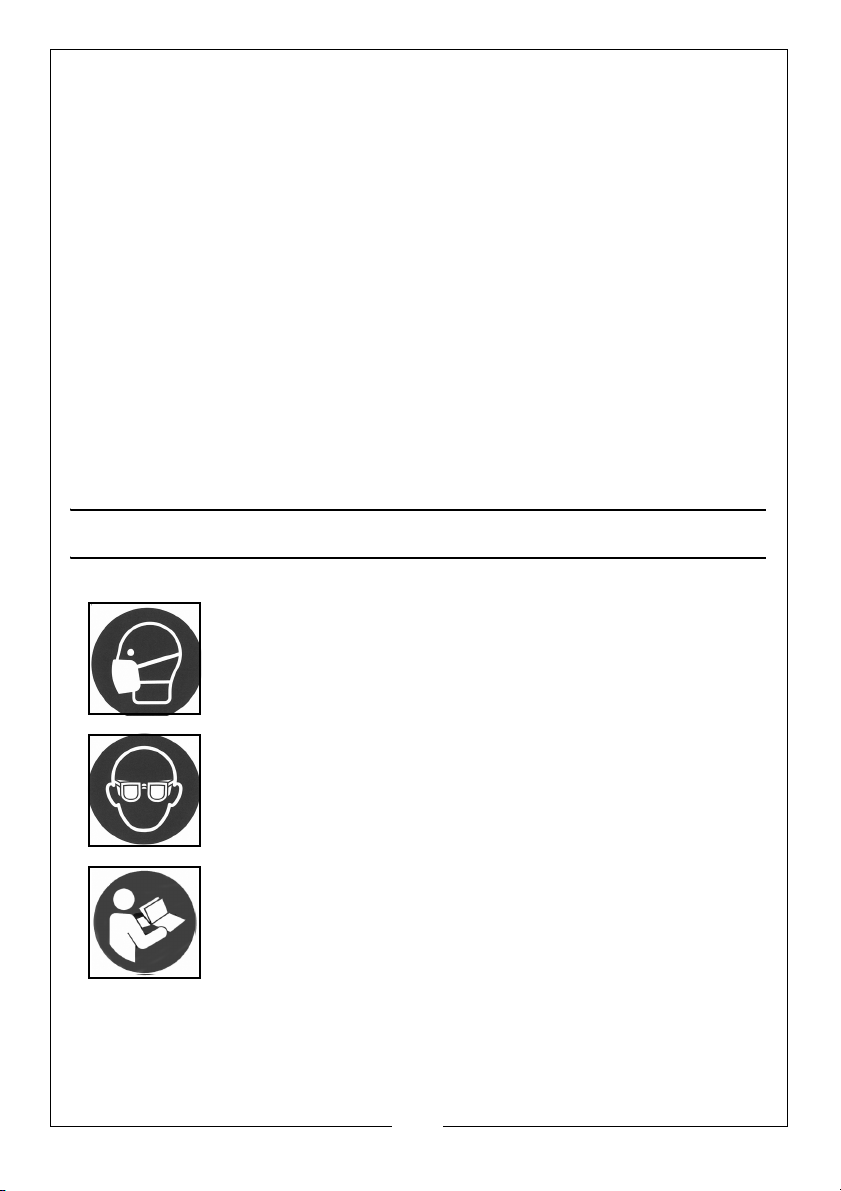
SAFETY SYMBOLS
The following safety symbols may be found on the machine.
Wear a dust mask
Wear eye protection
Read instruction manual before use
6
Parts & Service: 020 8988 7400 / E-mail: [email protected] or [email protected]
Page 7
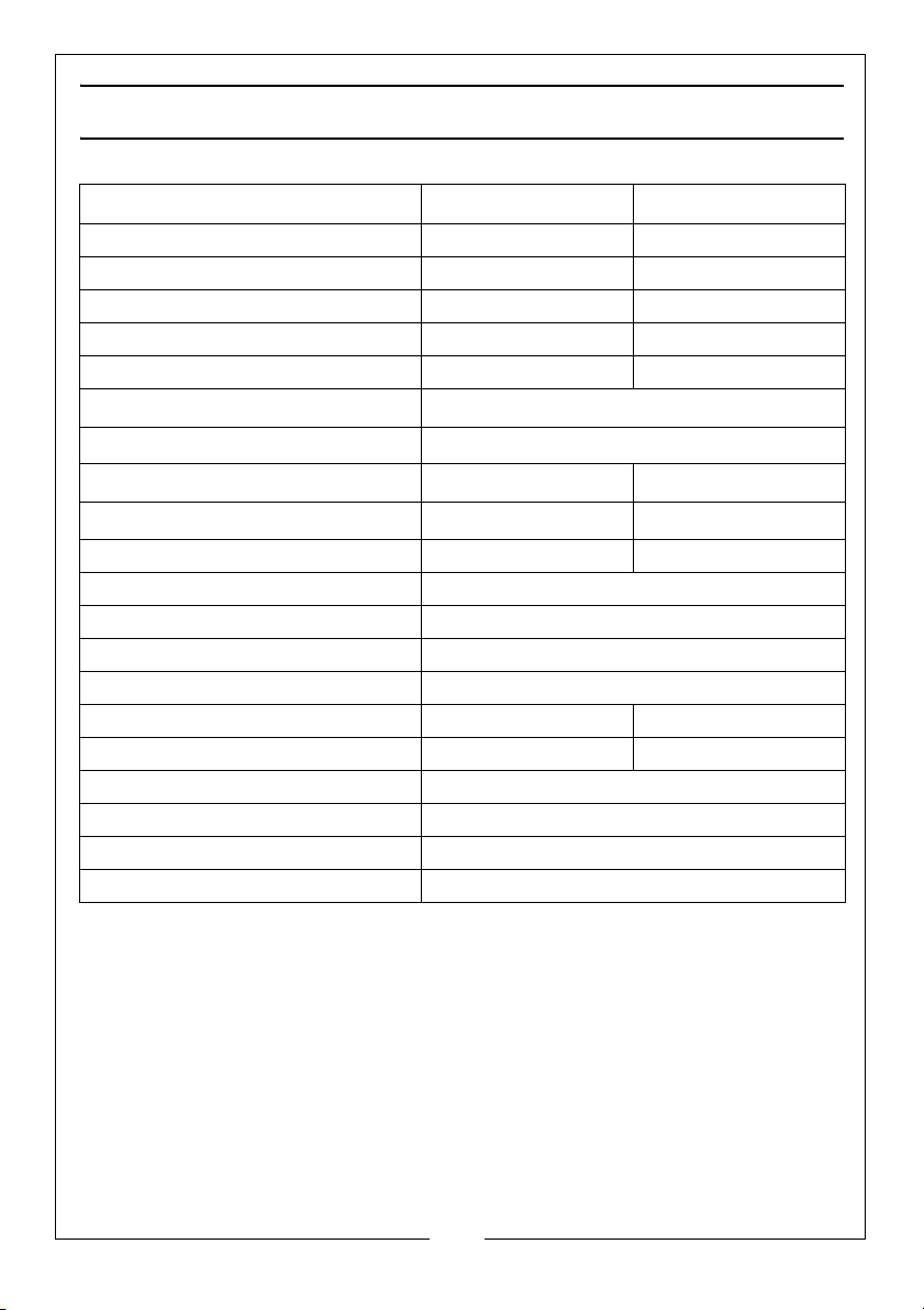
SPECIFICATIONS
CBS300 CBS350
Weight 50.2 kg 76.8 kg
Dimensions (W x D x H) 770 x 575 x 1586 mm 868 x 670 x 1705 mm
Table Size (W x D) 480 x 390 mm 545 x 515 mm
Throat Width 305 mm 340 mm
Table Height from Floor 990 mm 1005
Table tilt angle
Mitre Gauge Range
Maximum Cutting Depth@90
Maximum Cutting Depth@45
o
o
165 mm 225 mm
115 mm 160 mm
Left 60o / Right 60
Blade Length (welded loop) 2240 mm 2560 mm
Blade Width 12.5 mm
Blade Tooth Pitch 4 tpi
Blade thickness 0.5 mm
Supply Cable Length 2100 mm
Stand Footprint (W x D) 620 x 530 mm 670 x 530 mm
Rated Power @230V 750 W 1100
Blade Speeds 370 or 800 m/min
Duty Cycle S1 continuous
Sound Pressure Level (Lp) 70.7 dB(A)
Sound Power Level Measured (Lw) 83.7 dB(A)
0 - 45
o
o
7
Parts & Service: 020 8988 7400 / E-mail: [email protected] or [email protected]
Page 8
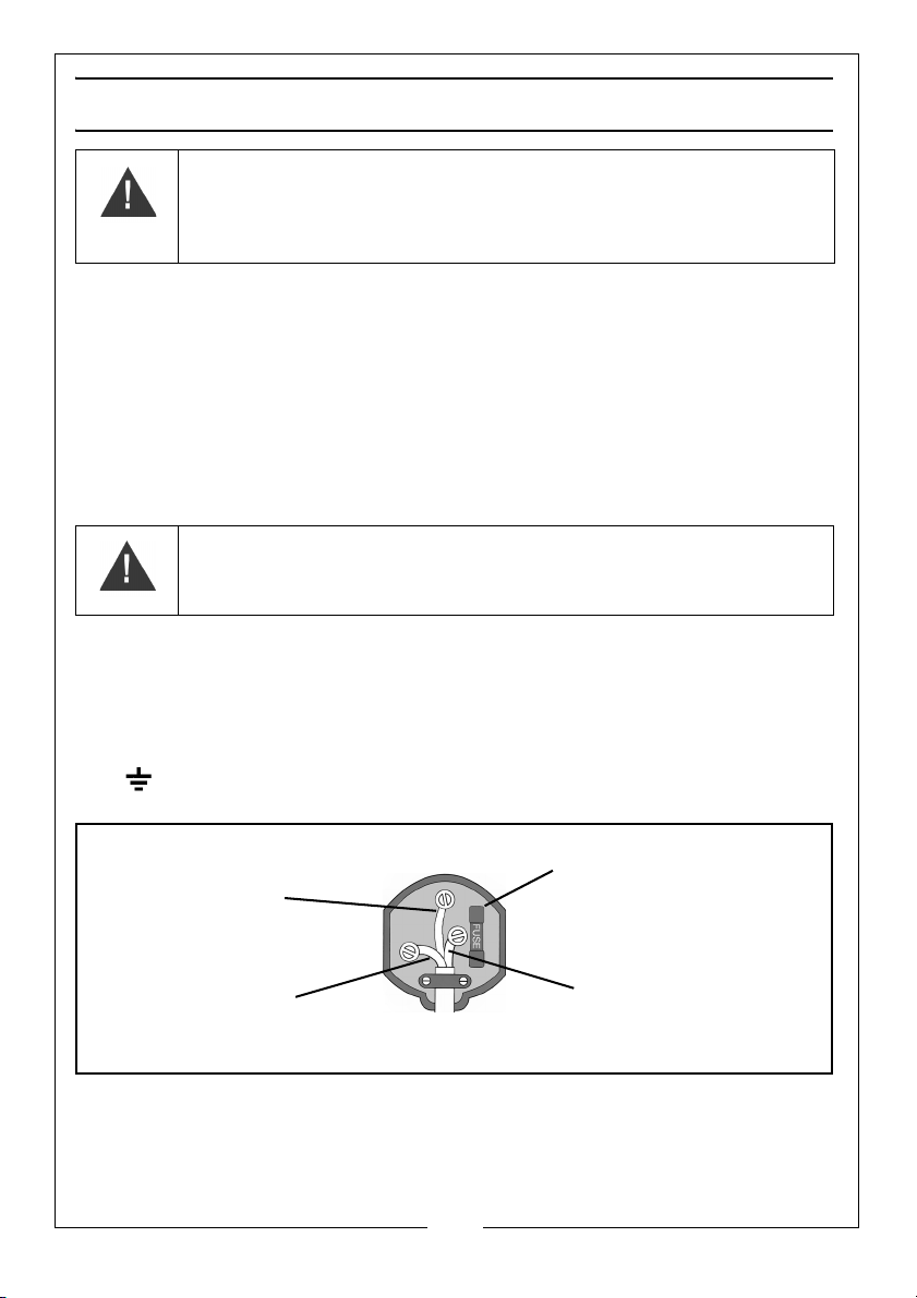
ELECTRICAL CONNECTIONS
Plug must be BS1363/A approved.
Always fit a 13 Amp fuse.
Ensure that the outer sheath of the cable is firmly held by the clamp
Neutral
(Blue)
Live
(Brown)
Earth
(Green and Yellow)
WARNING: READ THESE ELECTRICAL SAFETY INSTRUCTIONS
THOROUGHLY BEFORE CONNECTING THE PRODUCT TO THE MAINS
SUPPLY.
Before switching the product on, make sure that the voltage of your electricity supply is
the same as that indicated on the rating plate. This product is designed to operate on
230VAC 50Hz. Connecting it to any other power source may cause damage.
This product may be fitted with a non-rewireable plug. If it is necessary to change the
fuse in the plug, the fuse cover must be refitted. If the fuse cover becomes lost or
damaged, the plug must not be used until a suitable replacement is obtained.
If the plug has to be changed because it is not suitable for your socket, or due to
damage, it should be cut off and a replacement fitted, following the wiring instructions
shown below. The old plug must be disposed of safely, as insertion into a mains socket
could cause an electrical hazard
WARNING: THE WIRES IN THE POWER CABLE OF THIS PRODUCT ARE
COLOURED IN ACCORDANCE WITH THE FOLLOWING CODE:
BLUE = NEUTRAL BROWN = LIVE YELLOW AND GREEN = EARTH
If the colours of the wires in the power cable of this product do not correspond with the
markings on the terminals of your plug, proceed as follows.
•The Blue wire must be connected to the terminal marked N or coloured Black.
•The Brown wire must be connected to the terminal marked L or coloured Red.
•The Yellow and Green wire must be connected to the terminal which is marked E or
or coloured Green.
.
.
We strongly recommend that this machine is connected to the mains supply
via a Residual Current Device (RCD)
If in any doubt, consult a qualified electrician. DO NOT attempt any repairs
yourself.
Parts & Service: 020 8988 7400 / E-mail: [email protected] or [email protected]
8
Page 9
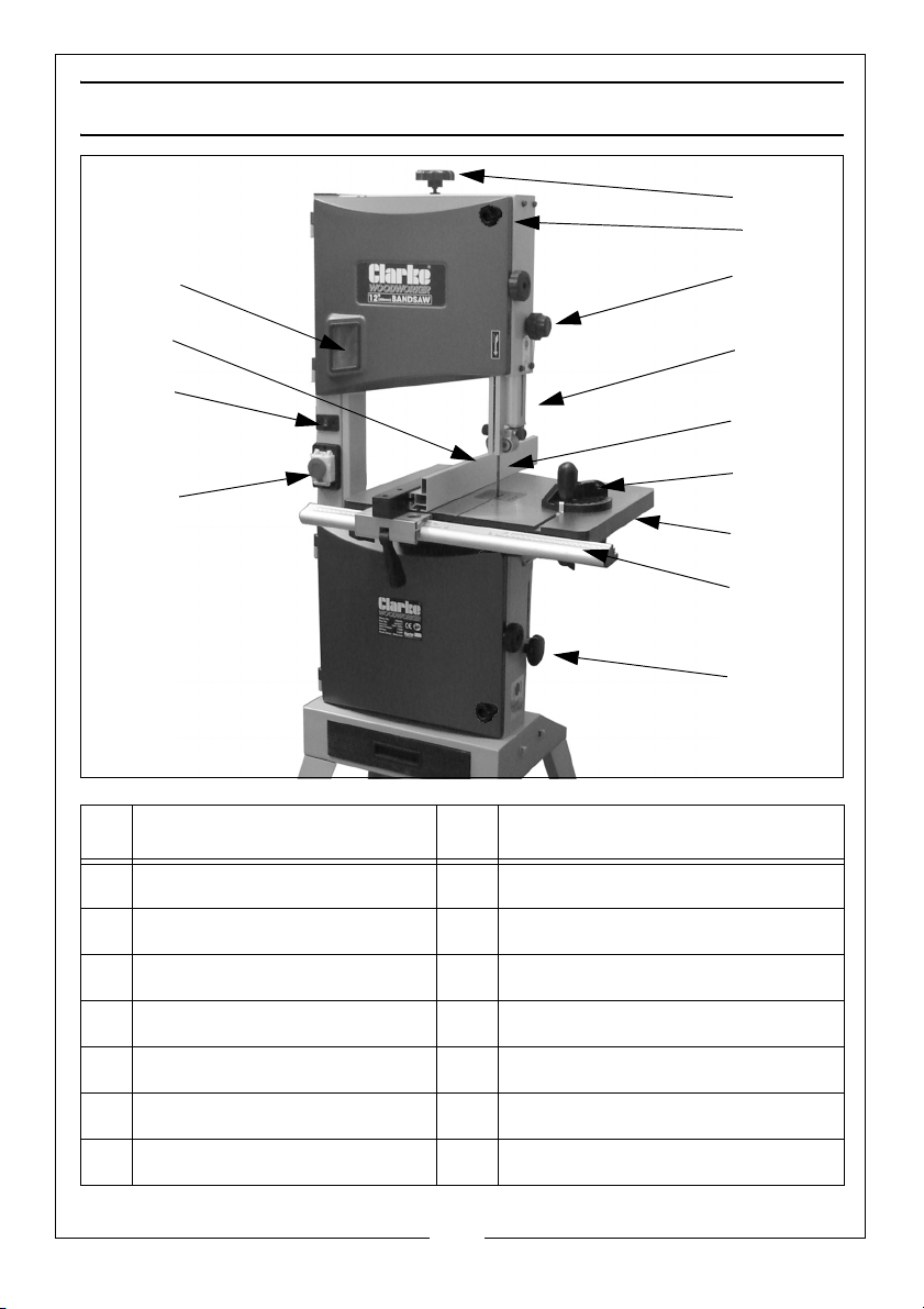
OVERVIEW
1
3
2
4
6
12
9
5
7
10
11
8
13
NO DESCRIPTION NO DESCRIPTION
1 Blade Tension Setting Knob 8 Drive Belt Setting Knob
2 Guide Height Setting Knob 9 Stop button
3 Adjustable Blade Guide 10 LED light switch
4 Bandsaw Blade 11 Rip Fence Assembly
5 Mitre Gauge Assembly 12 Band Tensioner Viewing Window
6 Tilting Work Table 13 Cover Safety Latch
7 Fence Support Guide Rail
9
Parts & Service: 020 8988 7400 / E-mail: [email protected] or [email protected]
Page 10
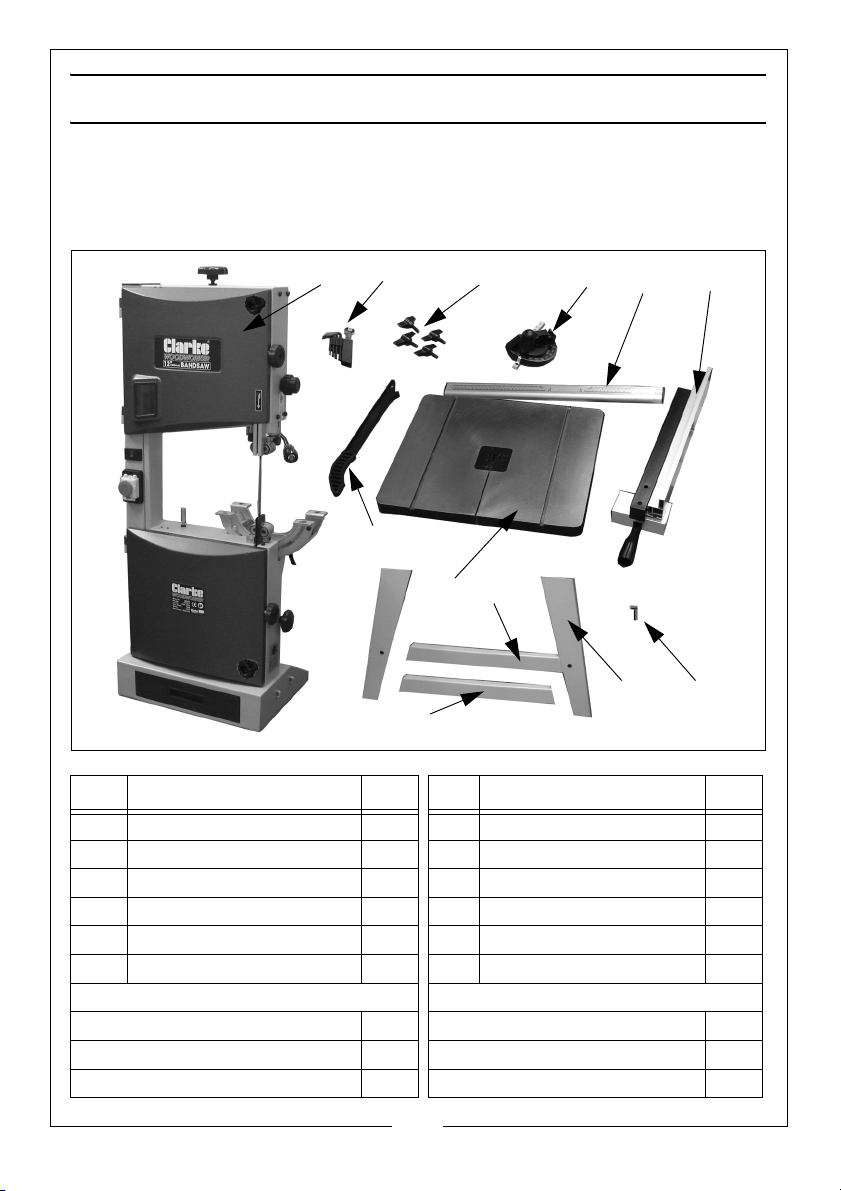
CONTENTS
1
3
2
4
6
9
8
5
7
10
12
11
Ensure the bandsaw and its components suffered no damage during transit
and that all components are present. Should any loss or damage be
apparent, please contact your CLARKE dealer immediately.
The following components are supplied with the bandsaw assembly.
Item Description Qty Item Description Qty
1 Bandsaw Assembly 1 7 Push Stick 1
2 Tool (wrench) Set 1 8 Table with Insert 1
3 Guide Rail Fixing Knobs 4 9 Long Braces 2
4 Mitre Gauge Assembly 1 10 Legs 4
5 Guide Rail 1 11 Push Stick Hook 1
6 Rip Fence 1 12 Short Braces 2
Fastenings kit containing:
Socket Head Bolts M8 x 12 12 6 mm Flat Washer 8
8 mm Flat Washers 12 M6 Nut 8
M6 x 12 Coach Bolts 8 M4 x 10 Screws 2
Parts & Service: 020 8988 7400 / E-mail: [email protected] or [email protected]
10
Page 11
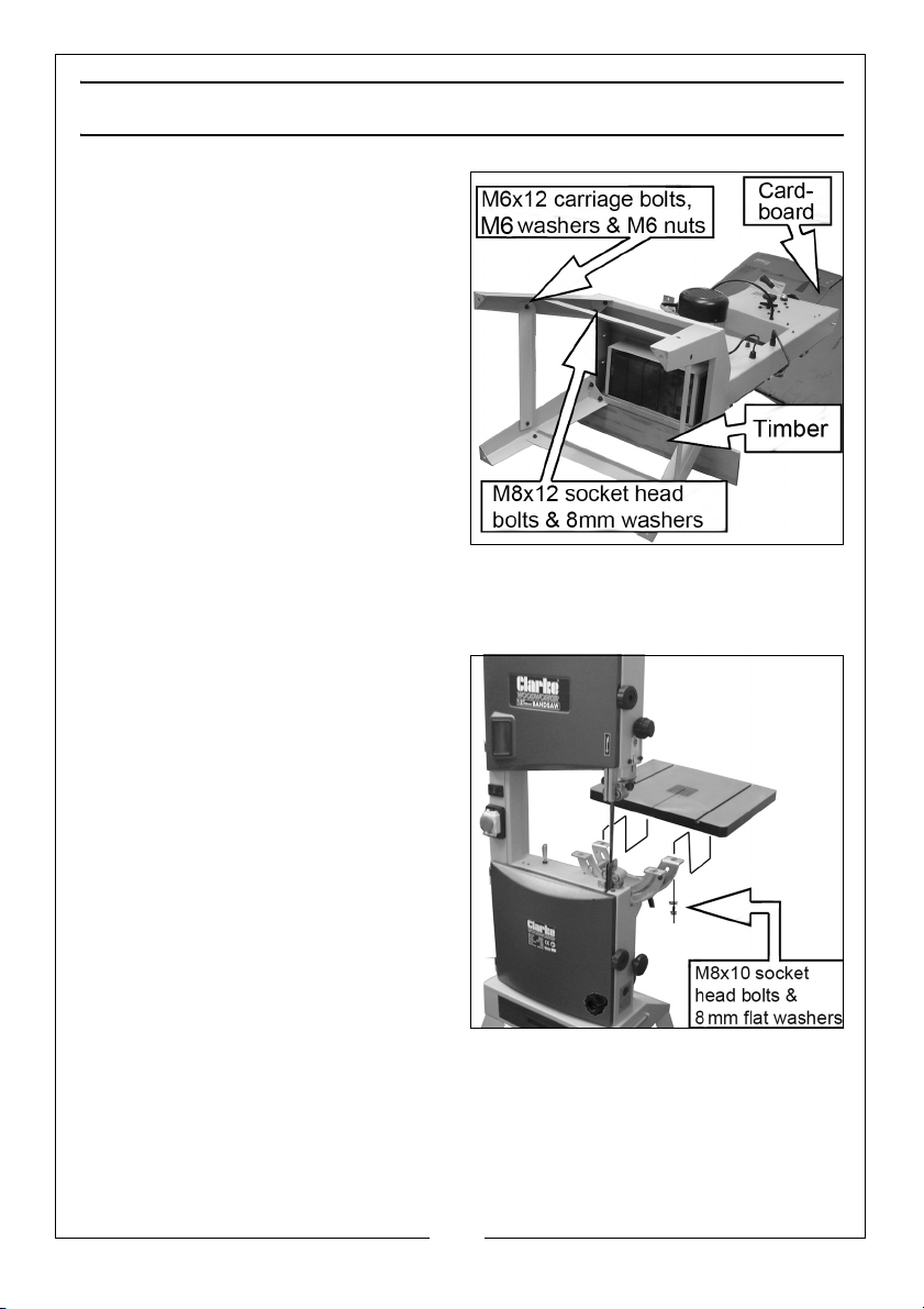
ASSEMBLY
1. Rest the bandsaw assembly on its
side, supported by a block of
timber as shown.
• Protect the upper casing from
damage with cardboard or rag
where it lays on the ground.
2. Attach the legs using the M8 x 12
socket head bolts and 8 mm flat
washers.
3. Fit the short and long braces to
the legs using M6 x 12 coachbolts,
6 mm flat washers and M6 nuts,
inserting the bolts from outside.
• Do not fully tighten the nuts at this
stage.
4. Stand the bandsaw upright on level ground and tighten all the bolts and
nuts, ensuring the assembly is level.
5. Fit the table to the bandsaw using
M8 x 10 bolts and 8 mm flat
washers. Ensure the saw blade is
central in the table slot.
11
Parts & Service: 020 8988 7400 / E-mail: [email protected] or [email protected]
Page 12
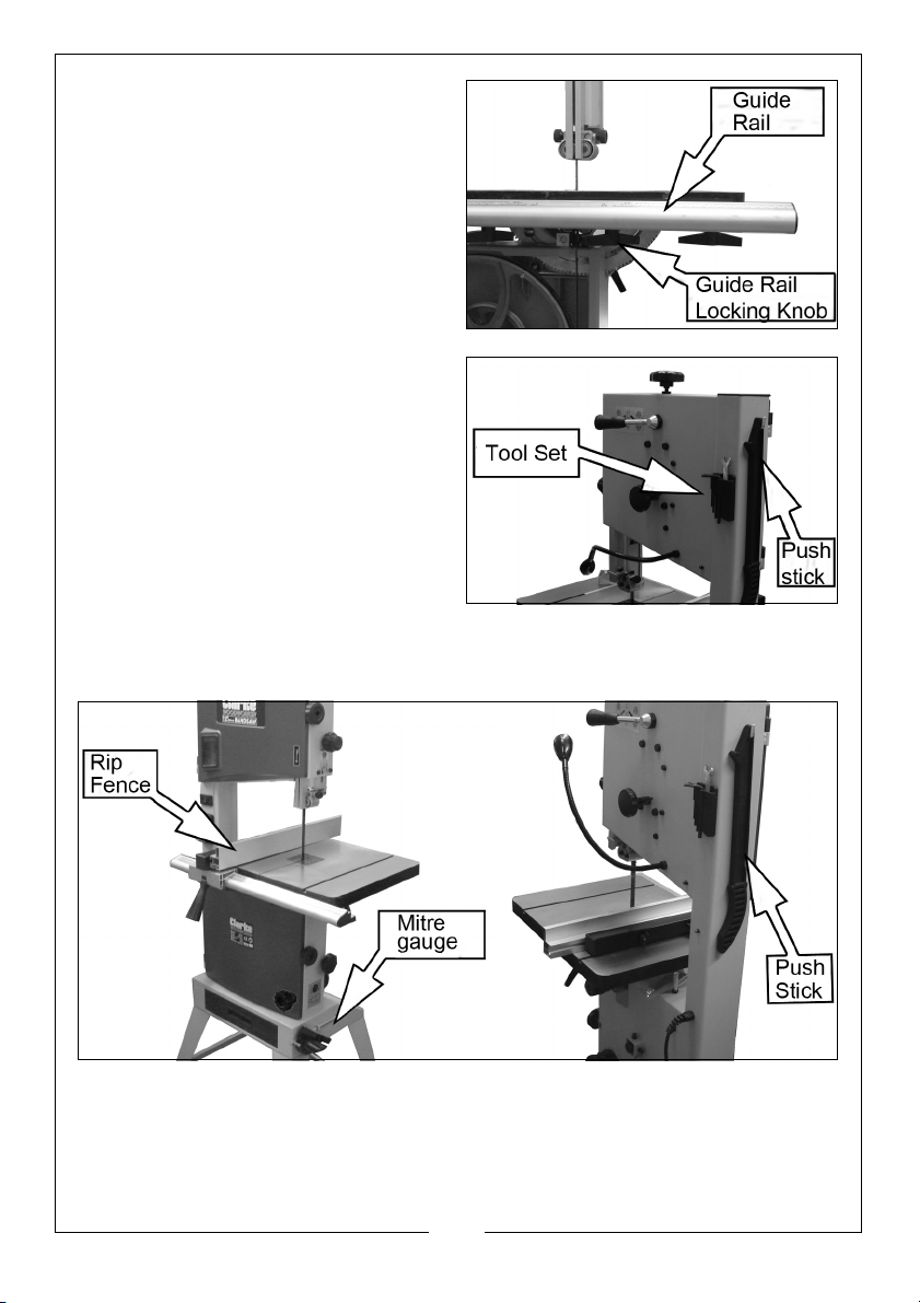
6. Secure the guide rail to the table
with the four locking knobs.
7. Fit the tool set holder to the
machine frame using the M4x10
screws. Install the loose tools (4 x
hex keys and a spanner).
8. Fit the push stick hook to the side
of the machine and tighten using
the unique locking nut.
9. Hang the push stick on the hook.
10. Fit the rip fence to the table over
the guide rail.
11. Store the mitre gauge in the loops provided on the lower frame base.
.
12
Parts & Service: 020 8988 7400 / E-mail: [email protected] or [email protected]
Page 13
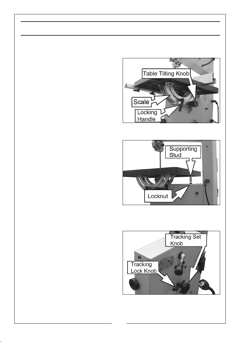
ADJUSTING THE PARTS
TILTING THE TABLE
1. Loosen the locking handle and
turn the table tilting knob to adjust
the table to the desired angle.
2. Use the angle indicator scale on
the table tilting bracket, to find
the desired angle.
3. Re-tighten the locking handle to
secure the table.
• For assured accuracy, we
recommend checking the tilt
angle using a protractor or set square.
4. With the table exactly level, it
should rest on the supporting stud
shown. Adjust the height of the
stud by screwing it in or out of the
frame and securing with the
locknut. Check with a set square
that the table is exactly level
when resting on the stud.
TRACKING THE SAW BLADE
If the saw blade does not run in the centre of the rubber tyre, the tracking
needs to be corrected by adjusting the tilt of the upper bandsaw wheel.
1. Open the upper and lower covers
by releasing the twist knobs and
the safety latches on the front of
the machine.
• Unscrew the safety latches fully to
release the cover panel.s.
• The panels will not move unless
the twist knobs are first released..
2. Loosen the tracking knob and
manually rotate the upper wheel,
taking care of the sharp blade.
13
Parts & Service: 020 8988 7400 / E-mail: [email protected] or [email protected]
Page 14
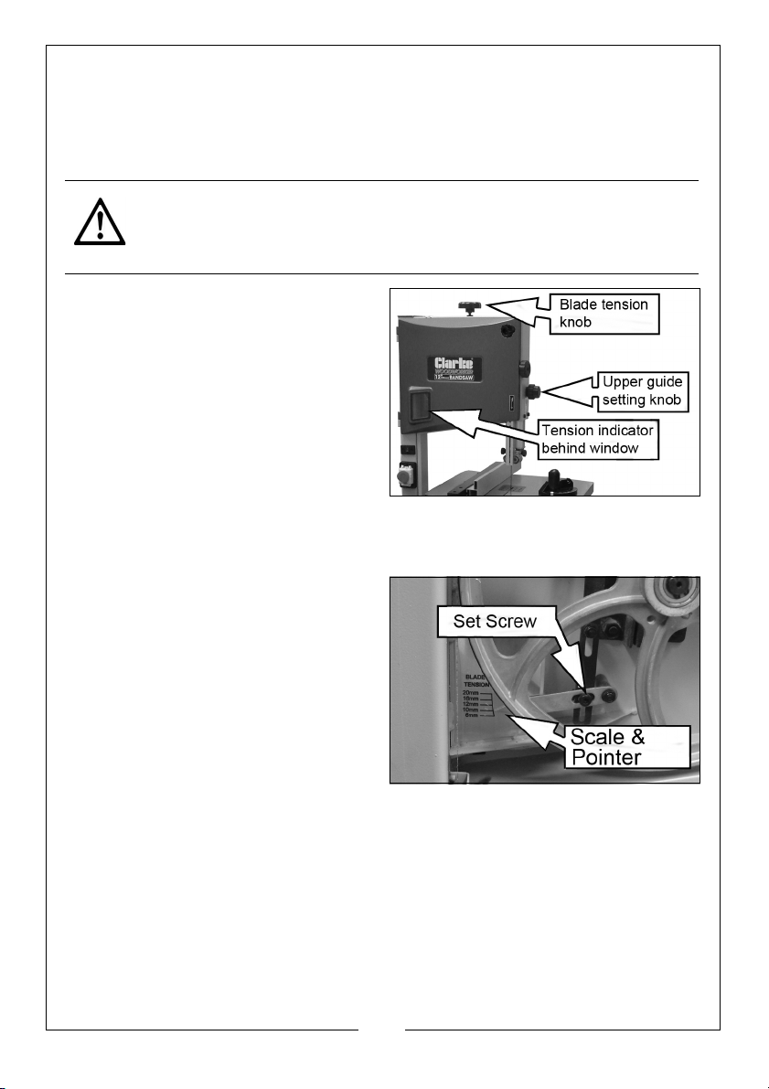
3. Turn the setting knob clockwise or anticlockwise until the saw blade tracks
centrally on the rubber tyre.
4. After adjusting, retighten the tracking lock knob and close the covers.
ADJUSTING THE BLADE TENSION
CAUTION: TOO MUCH TENSION CAN CAUSE THE SAW BLADE TO BREAK.
TOO LITTLE TENSION CAN CAUSE THE BLADE TO MAKE IRREGULAR CUTS
1. Raise the upper blade guide fully.
2. Check the tension by pressing
with a finger against the side of
the blade, halfway between the
table and upper guide.
• The blade should not flex more
than 2 mm.
3. Turn the blade tension knob to
adjust tension.
• Turning the blade tension knob clockwise will increase the blade tension.
BLADE TENSION INDICATOR
The blade tension indicator set screw
shown in the diagram is factory set to
the width of the blade supplied
(12mm). If a blade of a different
width is to be used, you will need to
make the following adjustment:
1. With the new blade installed,
adjust the blade tension knob until
the pointer aligns with the blade
width on the scale.
• The bandsaw can use blades of 6, 10,12,16 & 20 mm wide.
• The scale indicates the correct adjustment, depending on the blade
width.
14
Parts & Service: 020 8988 7400 / E-mail: [email protected] or [email protected]
Page 15
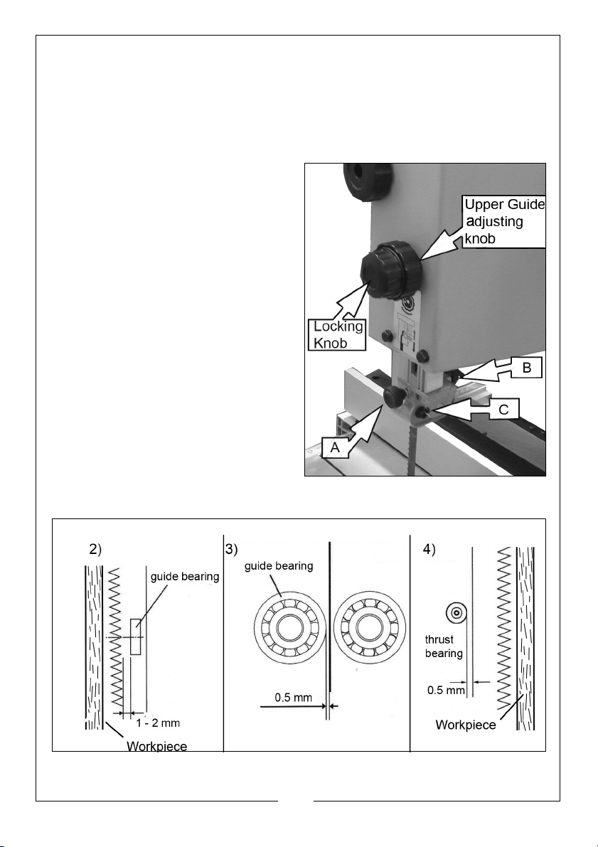
UPPER BLADE GUIDE ADJUSTMENT
GUIDE HEIGHT
The height of the blade guide needs to be adjusted prior to every cutting
operation to accommodate the height of the workpiece.
The upper blade guide should be set approx 3 mm above the workpiece.
1. Set the upper blade guide with
the adjusting knob to the desired
height by loosening the locking
knob and re-tightening after
adjustment.
GUIDE BEARING SETTING
2. Loosen the knob, (A) and adjust
the blade guide assembly so that
the guide bearing is positioned 1
or 2 mm from the back of the
blade. Re-tighten the knob (A).
3. Loosen the bolt (C) and adjust the
guide bearing to a position 0.5
mm away from the blade. Retighten the bolt (C).
4. Loosen the knob, (B) and adjust
the thrust bearing to a position, 0.5
mm from the rear of the blade.
Re-tighten the knob (B).
15
Parts & Service: 020 8988 7400 / E-mail: [email protected] or [email protected]
Page 16
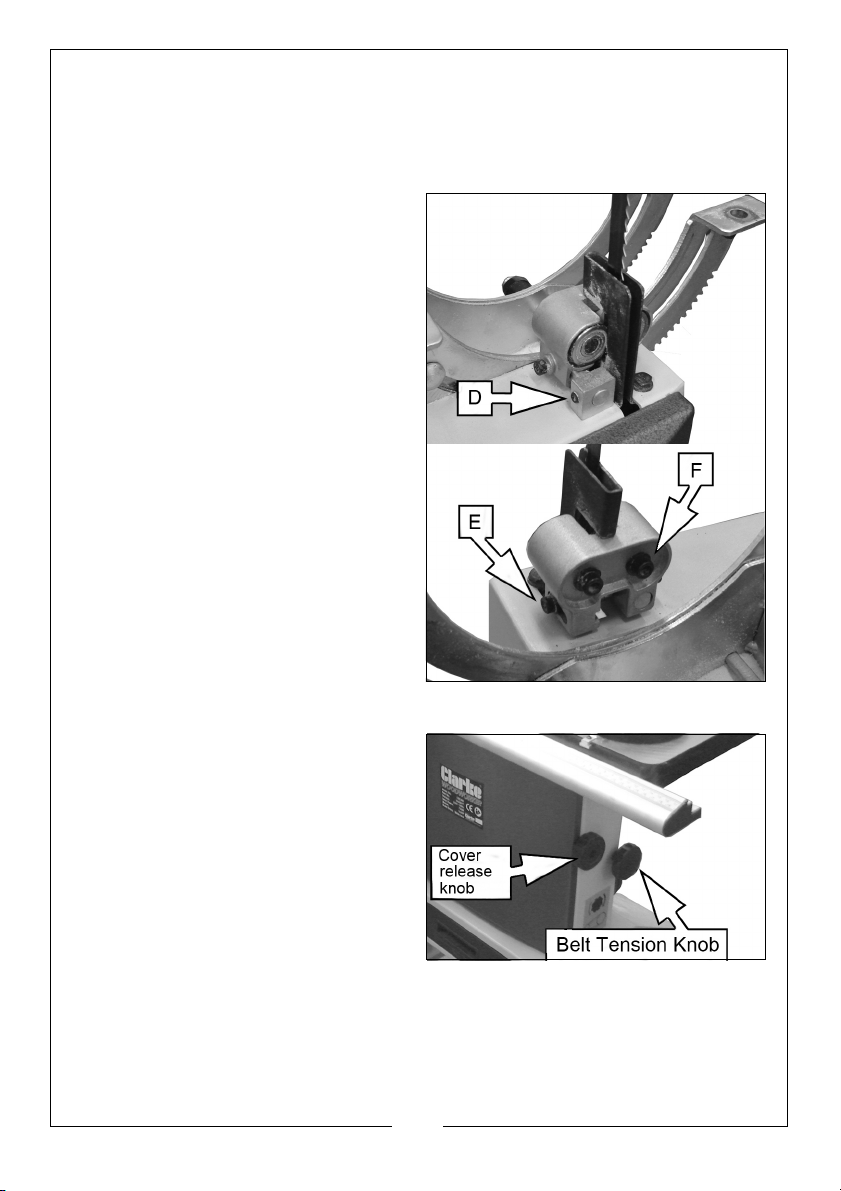
ALIGNING THE LOWER BLADE GUIDE
The lower blade guide needs to be re-adjusted after any blade change or
tracking adjustment.
• This task may be easier if the table is tilted for better access.
1. Loosen the screw (D), and move
the entire lower blade guide.
Adjust the guide bearing to a
position of 1 or 2 mm from the
back of the blade. Re-tighten the
set-screw.
2. Loosen the socket-head bolt (E),
and adjust the thrust bearing to a
position of 0.5 mm from the rear of
the blade. Re-tighten the bolt (E).
3. Loosen the socket head bolts (F),
and adjust the guide bearings to
a position of 0.5 mm from the sides
of the blade. Re-tighten the
socket head bolt (F).
CUTTING SPEED ADJUSTMENT
1. Open the lower cover by twisting
the cover release knob.
2. Slacken the driving belt by turning
the belt tension knob.
16
Parts & Service: 020 8988 7400 / E-mail: [email protected] or [email protected]
Page 17
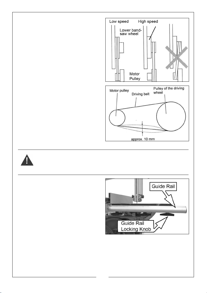
3. Put the driving belt on the
required pulley of the driving
wheel (lower band-saw wheel)
and the corresponding motor
pulley.
4. Turn the belt tension knob to
adjust the belt tension.
• Turn clockwise to reduce tension/
counter -clockwise to increase
tension.
• Half-way between the pulleys the
drive belt should be able to flex
approx 10 mm.
5. Close the lower cover.
CHANGING THE SAW BLADE
WARNING: THE TEETH OF THE BLADE ARE SHARP. BE SURE TO WEAR
GLOVES WHEN HANDLING THE BLADE IN SITUATIONS SUCH AS
UNPACKING, MOUNTING OR REPLACING.
1. Loosen the four lock knobs for the
guard rail and remove it.
2. Open the upper and lower
covers.
3. Set the upper blade guide to its
lowest position.
17
Parts & Service: 020 8988 7400 / E-mail: [email protected] or [email protected]
Page 18
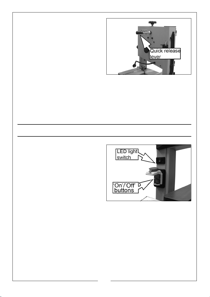
4. Loosen the quick-release lever
until the band saw blade has
slackened.
5. Remove the saw blade from the
machine.
6. Fit a fresh saw blade and centre
the blade on the rubber tyres of
the wheels.
7. Tighten the quick release lever.
8. Replace the guide rail in its original position.
9. Close the upper & lower covers.
10. Align the blade as described on page 13.
11. Adjust the blade tension as described on page 14.
12. Adjust the upper and lower blade guide as described on pages 14/15.
PREPARING FOR WORK
1. Lift the large red stop button,
which covers the green ‘ON’
button and press the green
button to start the bandsaw.
2. To stop the machine at any time,
press the large red stop button.
3. If required, switch the LED
worklight on or off using the rocker
switch.
4. Position the flexible LED worklight
as required.
18
Parts & Service: 020 8988 7400 / E-mail: [email protected] or [email protected]
Page 19
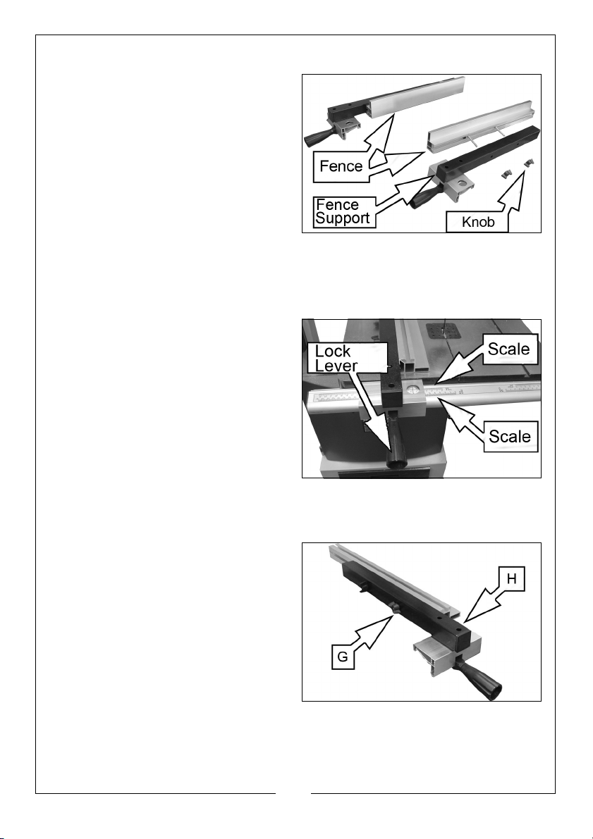
THE RIP FENCE
The rip fence can be used on both
sides of the blade. When the fence is
re-located from one side to the other,
it needs to be reversed as follows.
REVERSING THE FENCE
1. Loosen and remove the two
knobs.
2. Take off the fence with bolts and
retaining plate from the fence
support.
3. Re-fit the fence to the other side and replace the two knobs.
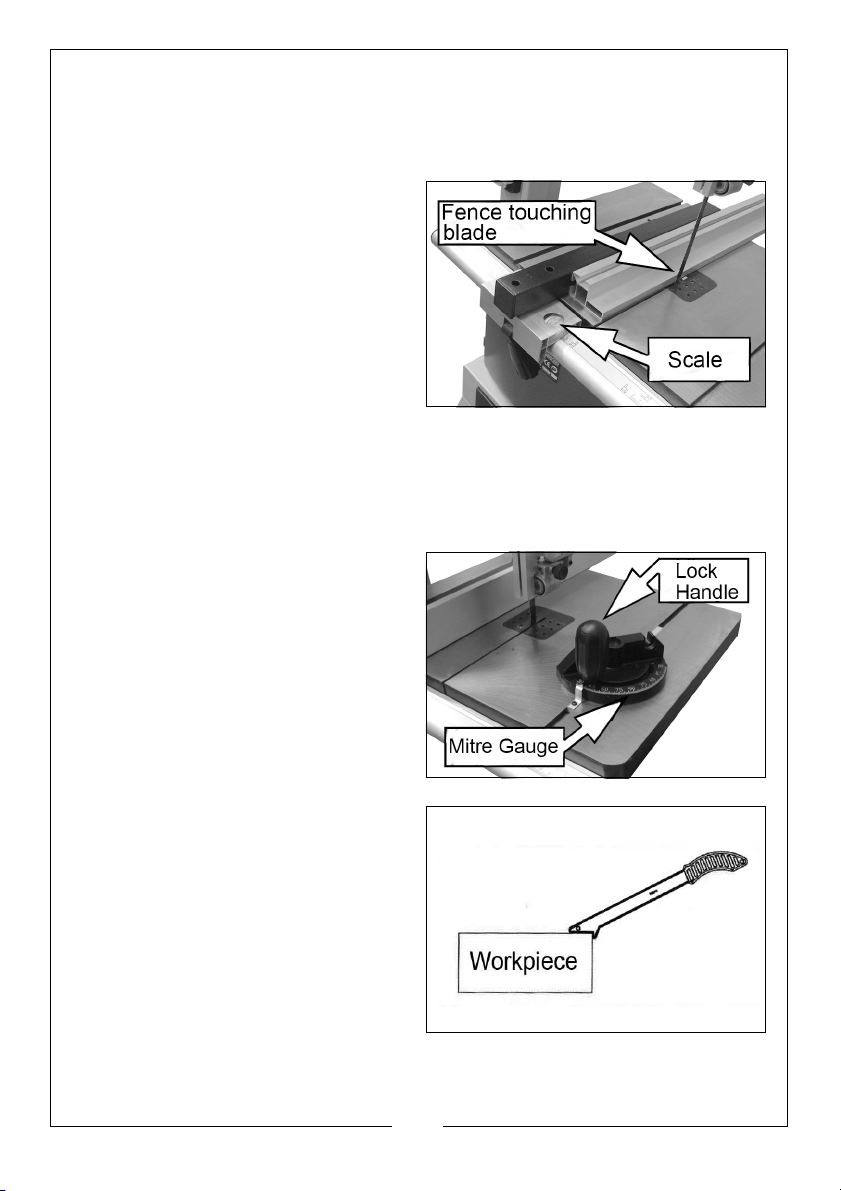
CLAMPING THE RIP FENCE
1. Place the rip fence over the guide
rail.
2. Move the fence to the required
position. The scale indicates the
distance from the saw blade to
the fence.
• Two scales are provided
according to whether the fence is
set vertically or horizontally as
described below.
3. Press down the lock lever to clamp the rip fence in position.
SETTING THE FENCE HEIGHT
The fence can be used in the upright
or laying down position. To re-fit the
fence to the fence support:
1. Loosen the two knobs (G).
2. Slide the fence out from the fence
support.
3. Rotate the fence 90o.
4. Insert the lock screw into the other
groove of the fence.
5. Re-tighten the two knobs (G).
19
Parts & Service: 020 8988 7400 / E-mail: [email protected] or [email protected]
Page 20
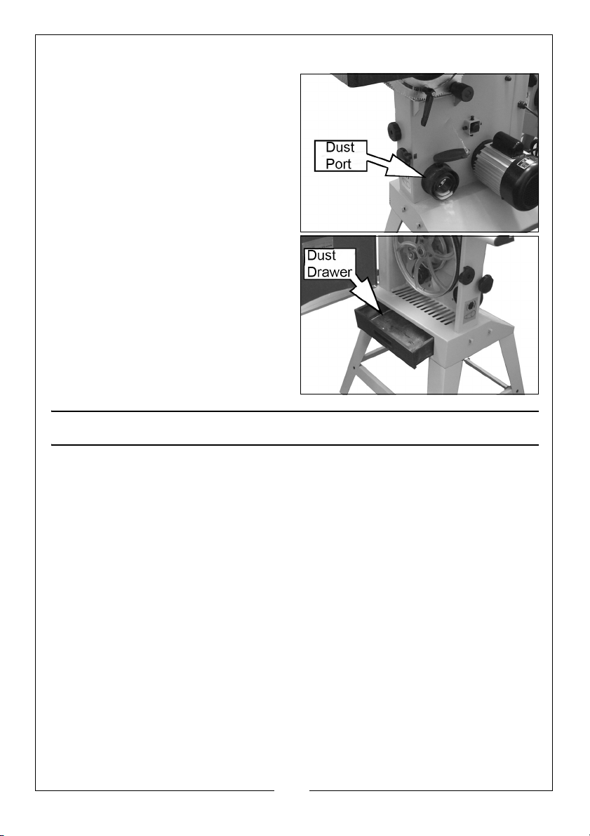
• The fence can be adjusted for accuracy when parallel to the side of the
blade by loosening the two socket bolts (H). Check the alignment with a
square before tightening the bolts.
ALIGNING THE FENCE WITH THE BLADE
To determine the distance of the
fence from the saw blade, the scale
on the fence guide rail must be set to
line up with the blade.
1. To do this, position the fence so
that it just touches the blade while
it is free to move along the guide
rail.
2. Loosen the guide rail locking
knobs and move the guide rail to
the side until the indicator scale is on ‘Zero’, then re-tighten the knobs
• If the fence is changed to the alternative height, the guide rail will need to
be re-set for that configuration.
USING THE MITRE GAUGE
The mitre gauge is inserted into the
table slot from the front edge.
The mitre gauge can be turned to
o
60
in both directions.
To set a mitre angle, loosen the lock
handle by turning it counterclockwise. Firmly tighten the handle
to secure the mitre gauge in position.
USING THE PUSH STICK
The push-stick serves as an extension
of the operators hand as protection
against accidentally touching the
saw blade.
The push-stick should be used if the
distance between the blade and rip
fence is less than approx 150 mm.
When not in use, the push-stick can
be stored on the hook provided on
the bandsaw frame.
Always replace the push-stick if lost or damaged.
20
Parts & Service: 020 8988 7400 / E-mail: [email protected] or [email protected]
Page 21
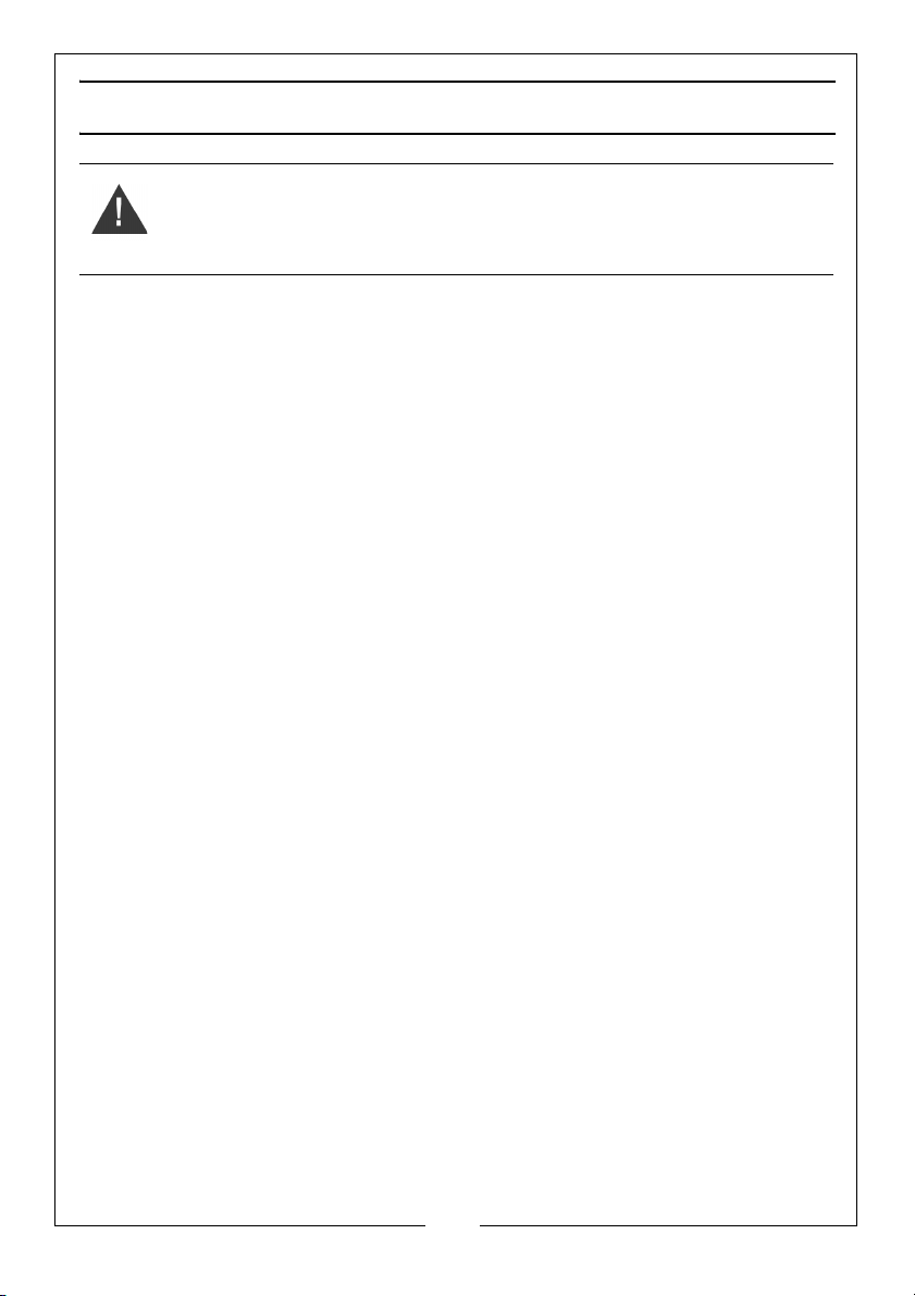
CONNECTING TO A DUST COLLECTOR
This bandsaw is fitted with a dust port
for connection to a dust collector if
available. Connections are available
in the following sizes:
• 50mm o/d
• 75mm o/d
• 100mm o/d
Other sawdust will fall into the dust
drawer which can be removed and
emptied as required. This is best
cleared out regularly.
PRACTICAL OPERATION
Before commencing work, ensure the work area is clean and tidy and the
machine table is clear of tools etc. Plan your work carefully and set the
machine up accordingly before switching on.
• Check the blade is correctly tensioned before use (see page 14).
• Set the upper blade guide as close as practical to the workpiece. This
provides the best safety for the operator and giving more accurate results
and greater control.
• Adjust the height of the upper blade guide to achieve the best control.
• Switch on and allow the saw blade to reach full speed before proceeding.
• Use both hands to feed the workpiece. The work must be held flat on the
table at all times to prevent binding of the blade. Use a steady, even
pressure, just sufficient to keep the blade cutting.
• Always use the rip fence or mitre gauge where possible to eliminate any
sideways movement of the work. This is most important when the table is
tilted at an angle.
• Remember that the blade removes material during the cut creating a gap
called the ‘kerf’, which must be allowed for when cutting to exact sizes.
21
Parts & Service: 020 8988 7400 / E-mail: [email protected] or [email protected]
Page 22

Plan your cut so that the kerf is the scrap side of the line you wish to cut.
Where necessary, allow a little more material for finishing.
• Always use a suitable holding device when cutting round or irregular
shaped timber to prevent twisting of the work piece.
TYPES OF CUT
Several types of cut are possible with this saw i.e. rip cutting, cross cutting,
bevel or mitre cutting.
RIP CUTTING
This term refers to cutting timber in the same direction as the grain, rather than
across it. You can rip wood freehand to a drawn pencil line, but best results
are obtained by using the rip fence.
If the table is set level, set the rip-fence to the left hand side of the blade,
allowing you to use your right hand to hold the work firmly against the fence.
The scale on the fence guide rail indicates the distance of the fence from the
saw blade and can be used as shown on page 20.
When cutting a bevel rip, with the table tilted at any angle up to 45o, set the
rip fence to the right hand side of the blade if the width of the workpiece
allows it. With the fence on the ‘downhill’ side of the table, it will help support
the workpiece.
The width of cut indicator (scale) on the guide rail may be used to set the rip
fence to the required cutting position.
Long workpieces may require additional support in the form of blocks or rollers
and may be pulled as well as pushed to pass them through the bandsaw.
CROSS CUTTING
This term refers to cutting timber at right angles to the grain. This type of cut
can also be made freehand, but the mitre gauge is used to ensure accurate
results. The mitre gauge can be adjusted up to 60
with the table tilted, compound mitre cuts.
Make sure the work is held firmly against the table and against the face of the
mitre gauge. Be careful to keep your fingers away from the blade, particularly
at the end of the cut.
o
to produce mitre cuts, and
MITRE CUTTING
Most crosscut work, especially with small pieces is more easily controlled with
the use of a mitre gauge. The mitre gauge is also essential for accurate
compound mitre cuts. The gauge is graduated to 60
hand angles.
22
Parts & Service: 020 8988 7400 / E-mail: [email protected] or [email protected]
o
for both left and right
Page 23
MAINTENANCE
WARNING: ALWAYS SWITCH OFF THE MACHINE AND DISCONNECT FROM
THE POWER SUPPLY BEFORE CARRYING OUT ANY CLEANING OF
MAINTENANCE TASKS.
CLEANING
Accumulated dust and chips should be removed from inside the bandsaw
frequently as well as emptying the dust drawer. Open the upper and lower
covers, use a soft brush and/or vacuum cleaner to remove sawdust. If
compressed air is used, ensure it is set to no more than 10 psi.
At the end of every work session, clean sawdust away from the motor vents.
CHANGING THE WHEEL PULLEY TYRES
Eventually the rubber tyres on the bandsaw pulley wheels will wear due to the
constant contact with the blade. Remove the saw blade as described on
page 17, then lift the edge of the tyre with a small screwdriver and carefully
work off the wheel. Ease on the new tyre, ensuring it sits evenly around the
wheel.
We recommend that both tyres (item 35, page 27) are changed at the same
time.
BLADE GUIDES
Blade guides should be inspected regularly for wear or chipping, and
replaced if necessary. See pages 14-16 for blade guide adjustments.
BEARINGS
All bearings used in the construction of your bandsaw and its motor are sealed
and lubricated for life.
STORAGE
Switch off the bandsaw and disconnect the power cable.
Cover the machine with a plastic bag and store it in a dry location.
23
Parts & Service: 020 8988 7400 / E-mail: [email protected] or [email protected]
Page 24
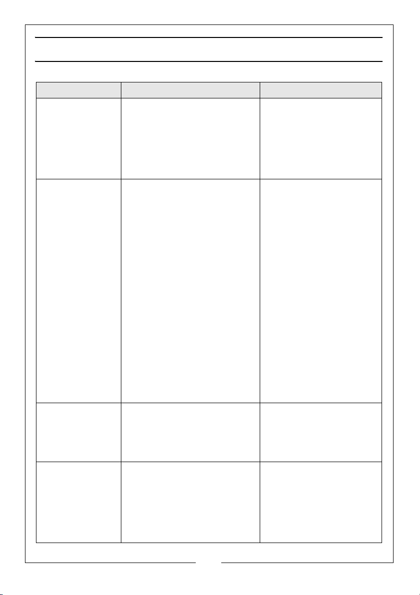
TROUBLESHOOTING
Problem Check Solution
The unit fails to
operate
Blade breaks 1. Faulty alignment (tracking)
Noise or vibration 1. Blade not correctly aligned.
Blade runs off the
cutting line
1. Check for power failure if
the unit is plugged in.
2. Check the switch is on and
that the fuse is not blown.
3. Upper or lower door
interlock switch not
engaged.
2. Blade guides incorrectly
adjusted.
3. Feeding the work too fast.
4. Forcing or twisting the blade
around a tight radius.
5. Blade too tight.
6. Blunt teeth.
7. Blade is badly welded or
brazed.
8. Wrong blade fitted.
9. Bandsaw left running when
not in use.
2. Guides not securely set.
1. Blade guides incorrectly
adjusted.
2. Blade tracking mal-adjusted
3. Blade tension too slack.
4. Wrong blade fitted (too
thin).
1. Plug the unit into the
socket.
2. Replace fuse or switch
on.
3. Check that upper/lower
doors are fully closed.
1. Carry out tracking
adjustments (p13).
2. Readjust blade guides
(p14/15)
3. Lower the feed rate
4. For tight curves, make
relief cuts fairly close
together at 90º to the
curve. A narrower blade
will make a tighter
curve.
5. Relieve blade tension
6. Renew blade
7. Renew blade
8. Fit only quality blades
supplied by your Clarke
dealer.
9. Always switch machine
off when not in use.
1. Carry out tracking
adjustments (p13).
2. Tighten the locking
knob. Check guides are
correctly set.
1. Re-adjust blade guides.
2. Carry out tracking.
adjustment (p13).
3. Re-tension blade.
4. Fit correct blade.
24
Parts & Service: 020 8988 7400 / E-mail: [email protected] or [email protected]
Page 25
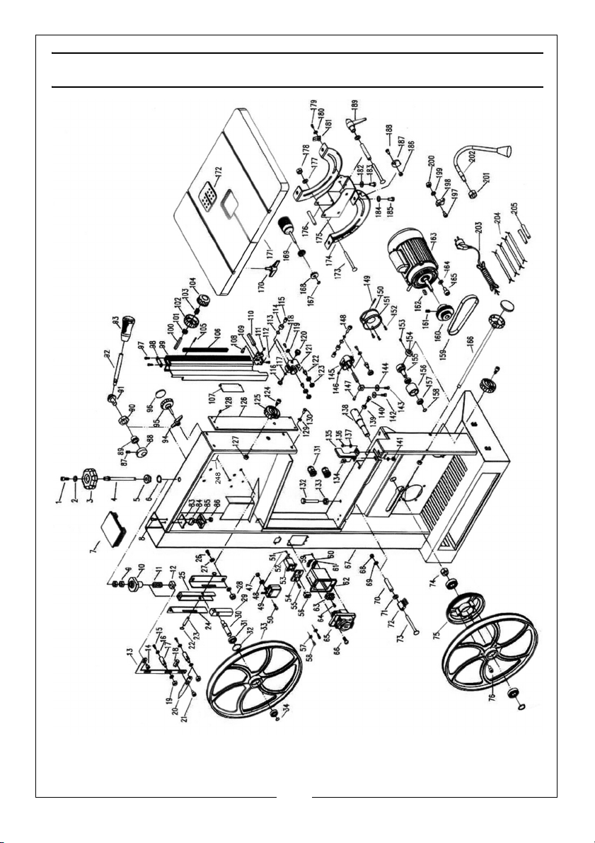
Page 26
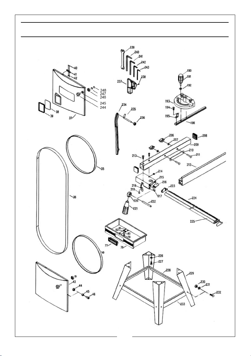
Page 27
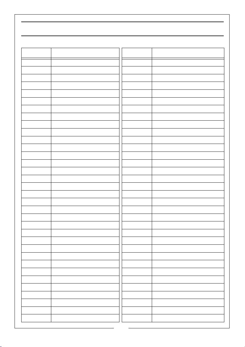
PARTS LIST
PART NO DESCRIPTION PART NO DESCRIPTION
1 5 x 12 socket head screw 35 ## Wheel Tread
2 5 mm Washer 36 ## Saw Blade
3 Blade Tension Knob 37 ## Upper Cover Panel
4 ## Blade Tensioner Screw 38 Window Glass
5Spacer 39Window Seal
6 3AMI-15 Circlip 40 4 x 10 X-head Screw
7 ## Frame End cap 41 Microswitch Actuating Clip
8 4 x 25 x-head s/t Screw 42 4 mm Nut
9 8 mm Nut 43 ## Lower Cover Panel
10 Cam 44 6 mm Locknut
11 Tension Coil Spring 45 Closing Spacer
12 Securing Nut 46 6 x 16 mm Socket Head Bolt
13 Pointer Support Plate 47 4 mm Cap Nut
14 Hex head bolt 48 4 mm Flat Washer
15 6 x 12 mm Set Screw 49 LED Worklight Switch
16 6 mm Flat Washer 50 4 x 12 mm Socket Head Screw
17 Stud Bolt 51 4.2 x 9.5 X-head Screw
18 Fixing Block 52 Cable Clamp
19 6 mm Locknut 53 LED Light Switch Box
20 ## Tension Pointer 54 LED Lamp Switch Face Plate
21 Hinge Bolt 55 4 x 12 mm X-head Screw
22 3AMI-8 Circlip 56 Switch
23 Adjusting Block Arbor 57 4 mm toothed Washer
24 Guide Rail Plate 58 4 x 8 mm X-head Screw
25 Tension Guide Block 59 2.9 x 9.5 x-head Screw
26 8 x 16 mm Set Screw 60 Cable Clamp
27 8 mm Flat Washer 61 Cable Clamp
28 8 mm Nut 62 Switch Box
29 Wheel Adjusting Block 63 Terminal Board
30 Upper Wheel Shaft 64 2.9 x 16 mm X-head Screw
31 Ball Bearing 65 Stop /Start Switch
32 3BMI-35 Circlip 66 4 x 12 mm X-head Screw
33 ## Bandsaw Pulley 67 ## Main Frame
34 3AMI-15 Circlip 68 8 mm Domed Nut
27
Parts & Service: 020 8988 7400 / E-mail: [email protected] or [email protected]
Page 28
PART NO DESCRIPTION PART NO DESCRIPTION
69 8 mm Flat Washer 106 Spring Pin
70 Brush Spacer 107 ## Guard Plate
71 8 mm Flat Washer 108 6 x 12 mm Socket Head Screw
72 Dust Brush 109 Connecting Block
73 8 x 90 mm Square Head Bolt 110 Connecting Shaft
74 20 x 1.5 mm Nut 111 6 x 8 mm Socket Set Screw
75 Spindle Pulley 112 4.8 x 13 mm X-Head Screw
76 6 x 10 mm Socket Head Bolt 113 10 mm Baffle Ring
77 Draw Handle 114 Needle Bearing
78 ## Dust Draw 115 Bearing Support
79 Steel Ball Spring 116 Finger Knob
80 8 mm Steel Ball 117 5 mm Flat Washer
81 2.9 x 9.5 mm X-head Screw 118 6 x 16 mm Socket Head Screw
82 Ball Fixing Sleeve 119 6mm Flat Washer
83 Microswitch Box Cover 120 Knob
84 Microswitch 121 Guide Block
85 Microswitch Box 122 Bearing Support
86 4 mm Nut 123 Ball Bearing
87 6 x 8 mm Socket Set Screw 124 6 x 16 mm Socket Head Screw
88 Quick Release Cam 125 Door Closing Handle
89 Cam Axis Guide 126 ## Guide Plate
90 20 x 1.5 mm Nut 127 6 mm Locknut
91 Cam Shaft 128 6 x 8 mm Socket Head Screw
92 Quick Release Arm 129 6 mm Flat Washer
93 Quick Release Handle 130 6 x 10 mm Socket Head Screw
94 Tracking Lock Knob 131 Cable Gland
95 Tracking Setting Knob 132 Table Stop Rod
96 Handle Cover 133 8 mm Nut
97 4.8 x 13 mm X-head Screw 134 Fixing Block
98 Locating Plate 135 Lower Blade Guide Plate
99 ## Blade Guard Cover 136 6 x 12 mm Set Screw
100 Spindle 137 6 mm Flat Washer
101 Guide Adjustment Pinion 138 Lower wheel spindle
102 Guide Adjustment Knob 139 6 mm Nut
103 Guide Adjustment Spring 140 6 x 16 mm Set Screw
104 Guide Locking Handle 141 6 mm Nut
105 Rack 142 6 x 8 mm Set Screw
28
Parts & Service: 020 8988 7400 / E-mail: [email protected] or [email protected]
Page 29
PART NO DESCRIPTION PART NO DESCRIPTION
143 6 x 10 mm Set Screw 180 4 mm Flat Washer
144 6 mm Flat Washer 181 Pointer
145 Lower Guide Block 182 6 mm Flat Washer
146 6 x 8 mm Socket Head Bolt 183 6 x 10 Bolt
147 5 x 10 mm Socket Head Bolt 184 8 mm Flat Washer
148 5 x 25 mm Socket Head Bolt 185 8 x 10 Socket Head Bolt
149 3 x 22 mm Pin 186 6 mm Nut
150 Dust Port Cover 187 Spacing Shim
151 Dust Port 188 6 x 10 Set Bolt
152 4.2 x 13 mm X-Head Screw 189 8mm Locking Handle
153 6 x 8 mm Socket Head Bolt 190 Knob Cap
154 Locating Ring 191 Mitre Lock Handle
155 Tensioner Pulley Spindle 192 Plastic Washer
156 Belt Tension Pulley 193 Mitre Gauge
157 Ball Bearing 194 4 x 8 mm X-Head Screw
158 3AMI-12 Circlip 195 Angle Pointer
159 ## Drive Belt 196 Mitre Guide Bar
160 Motor Drive Pulley 197 5 x 12 mm Socket Head Screw
161 8 x 8 mm Socket Grub Screw 198 Cable Clamp
162 Key 199 5 mm Flat Washer
163 ## Drive Motor 200 5 mm Cap Nut
164 6 mm Flat Washer 201 10 mm Retaining Nut
165 6 x 12 mm Socket Head Bolt 202 Flexible LED Lamp
166 Idler Tension Adjusting Rod 203 Power Cable
167 3AMI-18 Circlip 204 Small Cable
168 Table Tilting Pinion Gear 205 Insulator Sleeve
169 Table Tilting Lock Handle 206 Wing-nut
170 Tension Knob 207 6 mm Flat Washer
171 ## Work Table 208 Plastic End Cap
172 Table Insert 209 Fence Support Bar
173 Square Neck Bolt 210 Fence Securing Plate
174 Table Tilting Bracket 211 6 x 50 mm Coachbolt
175 Rotary Support Bracket 212 ## Parallel Fence
176 Spacer Sleeve 213 5 x 10 mm Socket Head Bolt
177 8 mm Washer 214 5mm Square Nut
178 8 mm Locknut 215 Fence Mounting Bracket
179 4 x 12 mm X-head screw 216 Plastic Pointer
29
Parts & Service: 020 8988 7400 / E-mail: [email protected] or [email protected]
Page 30
PART NO DESCRIPTION PART NO DESCRIPTION
217 2.9 x 9.5 mm X-head screw 233 Short Support Beam
218 Fence Locking Leaf Spring 234 Push Stick
219 5 x 8mm X-Head Screw 235 Push Stick Retaining Hook
220 Fence Locking Cam 236 6 mm Nut
221 Fence Locking Lever 237 Tool Holder
222 Fence Locking Spindle 238 4 x 10mm X-Head Screw
223 Guide End Closing Cap 239 8-10 mm Open Wrench
224 ## Guide Calibrated Scale 240 6 mm Hex (Allen) Key
225 Guide Rail 241 5 mm Hex (Allen) Key
226 8 mm Flat Washer 242 4 mm Hex (Allen) Key
227 8 x 10 Socket Head Bolt 243 3 mm Hex (Allen) Key
228 ## Long Support Beam 244 Cover Safety Latch Knob
229 Supporting Leg 245 Cover Safety Latch Bush
230 6 mm Nut 246 Cover Safety Latch Spacer
231 6 mm Flat Washer 247 Cover Safety Latch Nut
232 6 x 12 mm Square Head Bolt 248 Cover Safety Latch Circlip
Items marked ## must be specified according to whether CBS300 or 350 model.
30
Parts & Service: 020 8988 7400 / E-mail: [email protected] or [email protected]
Page 31
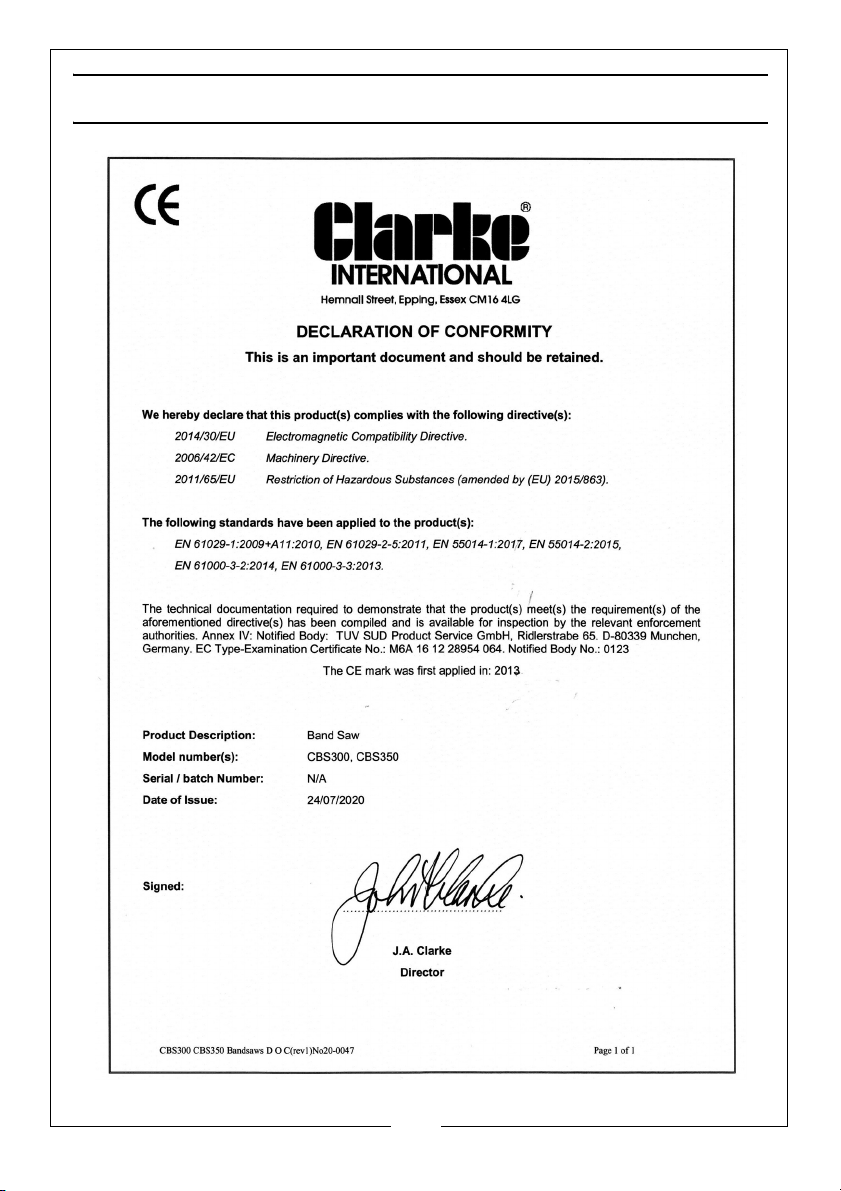
DECLARATION OF CONFORMITY
31
Parts & Service: 020 8988 7400 / E-mail: [email protected] or [email protected]
Page 32

 Loading...