


©
305mm (12”) Portable Bandsaw
305mm (12”) Portable Bandsaw
Model CBS12WV
Model CBS12WV
Part Number 6460030
OPERATING & MAINTENANCE
INSTRUCTIONS
0107

Spare Parts Diagram
©
Copyright Clarke International. October, 2000. All rights reserved
2
15
Spare Parts List
Specifications
No. Description Part No. No. Description Part No.
2 Wheel HT14600203
3 Hex Nut HT270100312
7 Mitre Shaft HT2601008112
11 Knob Screw HT14601101
12 Switch Box HT14601201
13 Machine Screw HT2651011112
15 Switch Cover HT14601501
16 Mitre Shaft HT2601057112
17 Knob Screw HT14601701
18 Hex. Screw HT2611105112
21 Screw HT775515
22 Guide Holder HT14602201
23 Blade Guard HT14602301
24 Ball Bearing HT280120635
25 Mitre Shaft HT2621013112
26 Hex. Nut HT270100312
28 Motor HT12056
29 Motor Cover HT14602901
30 Self-Tap Screw HT845519
31 Spring Seat HT14603101
33 Drive Gear HT14603301
34 Shaft HT14603401
35 Screw HT14603501
36 Washer HT2920073
37 C. S. Washer HT14603702
38 Set Screw HT2621031112
39 Washer HT254201322
40 Machine Screw HT2651104112
41 Spiral Spring HT14604101
42 Set Screw HT2621017112
43 Table Tilt Truss HT14604301
44 Square Nut HT397606
45 Machine Screw HT2641017112
46 Self-Tap Screw HT8453512
47 Speed Switch HT14604701
48 Machine Screw HT2651108112
50 Timing Belt HT301204
51 Hex. Nut HT270100412
53 Hex. Head Bolt HT2601023112
54 Drive Wheel HT14605402
55 Screw HT1460550
56 Front Cover HT14605601
57 Wheel Body HT14605601
58 Machine Screw HT2651047112
60 Angle Pointer HT14302401
61 Machine Screw HT2651010113
62 Insert Plate HT14606201
63 Table HT14606301
67 Base HT14606701
68 Electronic Switch HT286007
69 Wheel Support HT14606902
70 Saw Blade 6470031
71 Micro-Switch HT3013020
77 Machine Screw HT2641005112
78 Mitre Gauge HT14607801
79 Angle Pointer HT14302401
81 Machine Screw HT2651010113
83 Knob Screw HT14608301
85 Guide Bar HT14608502
86 Clamp HT10308202
89 Machine screw HT818850320
90 Hex Nut HT617003
92 Wire HT278035
95 Nameplate HT14609502
97 Nameplate HT14609701
98 Nameplate HT14609802
99 Knob HT301305
103 Machine Screw HT81885412
104 Earthplate HT30013
105 Washer HT958504
106 Spring Washer HT937604
107 I.G.Washer HT861760
108 Guide Holder HT300902
109 Washer HT300303
110 Hex. Nut HT617006
111 Washer HT958508
112 C. S. Washer HT89418606
113 Ball Bearing HT80029
114 H. S. Washer HT89318626
115 C. S. Washer HT89418609
116 Rubber Tyres HT300505
117 Motor Brush Set see dealer
Model No. ..................................................................................... CBS12WV
Part No. .......................................................................................... 6460030
Motor ............................................................................................. 230V 50Hz 1Ph
Power Rating ................................................................................. 550 Watts
Motor Speed ................................................................................. 1430rpm max.
Blade Speed .................................................................................
Max. Depth of Cut ........................................................................ 85mm (3 5/16”)
Max. Throat Width ......................................................................... 305mm (12”)
Table Tilt ......................................................................................... 0-45 Degrees
Table Size ...................................................................................... 345 x 345mm
Dust Port ......................................................................................... 41.5mm
Weight............................................................................................ 15.5kg
Noise Level .................................................................................... 90dB LWA*
*(Sound Power Level) Cutting 25mm soft wood at maximum speed
Do not dispose of this product with general waste. It must be disposed of according to law at an
approved disposal facility.
200-600 M/Min under Load
Restrictions of Use
This saw is NOT suitable for cutting:
•
Timber greater than 110mm in depth.
•
Metal, stone, rubber, plastic, bones, etc.
•
Logs or round timber.
Spare Parts & Service Contacts
For Spare Parts and Service, please contact your nearest dealer,
or CLARKE International, on one of the following numbers.
PARTS & SERVICE TEL: 020 8988 7400
PARTS & SERVICE FAX: 020 8558 3622
or e-mail as follows:
PARTS: Parts@clarkeinternational.com
SERVICE: Service@clarkeinternational.com
14
3

Thank you for purchasing this Clarke 12 inch Bandsaw. This machine is designed to rip and
cross cut wood exclusively and for DIY, and hobby use ONLY. Before attempting to operate
this machine, please read this instruction manual thoroughly and follow all directions carefully.
This is for your own safety and that of others around you, and to help you achieve long and
trouble free service from your bandsaw.
Guarantee
This product is guaranteed against faults in manufacture for 12 months from purchase date.
Please keep your receipt as proof of purchase.
This guarantee is invalid if the product has been abused or tampered with in any way, or
not used for the purpose for which it is intended. The reason for return must be clearly stated.
This guarantee does not affect your statutory rights.
For your own Safety
WARNING!
operating instructions, and before using the equipment.
✔ ALWAYS wear suitable safety goggles, manufactured to the latest European Safety
Standards, when using the bandsaw.
✔ ALWAYS keep your hands and fingers clear of the blade when sawing. Use a push stick
with small workpieces.
✔ ALWAYS set the blade guide/guard assembly as close as possible to the workpiece.
✔ ALWAYS switch off the saw, and make sure the blade has come to a complete stop
before clearing sawdust or off-cuts from the table.
✔ ALWAYS keep the saw properly adjusted, paying particular attention to the blade tension
and tracking, and the blade guides.
✔ ALWAYS disconnect the saw from the mains supply before removing the front cover.
✔ ALWAYS make sure ON/OFF switch is in ‘OFF’ position before plugging in. Avoid
accidental starting.
✔ ALWAYS keep children away. All visitors should be kept a safe distance from the work
area, especially while operating unit.
✔ ALWAYS use in a well ventilated area. Remove sawdust frequently. Clean out sawdust
from the interior of the saw to prevent a potential fire hazard.
✔ ALWAYS Wear proper apparel. Loose clothing or jewellery may get caught in moving
parts. Wear protective hair covering to contain long hair.
✘ NEVER leave this saw running unattended. Turn power OFF. Don’t leave tool until it
comes to a complete stop.
✘ NEVER operate this saw while under the influence of drugs, alcohol or any medication.
✘ NEVER attempt to free a stalled saw blade without first turning the saw OFF. Turn off `
power switch immediately to prevent motor damage.
Read these safety instructions in conjunction with the
Replacing the Saw Blade: (Ref: Fig.4)
The saw blade is not easy to sharpen, and we recommend fitting a replacement when the
blade becomes blunt, loses its set, or becomes bent or cracked. Replacement blades are
available from your local dealer or Clarke International Spare Parts Department.
1. Remove the table by first removing the table set screw then fully unscrewing the securing
knobs.
2. Back off all blade guides and blade supports as detailed under ‘Blade Guide
Adjustments’ on page 10.
3. Remove the front cover to gain access to the blade.
4. Turn the blade tension locking knob (25) one complete turn anticlockwise.
5. Turn the blade tension Hex. socket head adjuster screw (24) fully anticlockwise to relieve
all tension from the blade.
5. Carefully pull the blade from the wheels taking great care not to damage your hands
on the teeth. It is recommended that a pair of industrial gloves be worn for this task.
6. Position the new blade over the wheels, feeding it through the blade guides, ensuring
that the teeth point downwards toward the table. Position it as close to the centre of
each wheel as possible.
7. Turn the blade tension locking knob clockwise and correctly tension the blade.
8. Carry out tracking checks and adjust if necessary.
9. Readjust all blade guides and blade supports as detailed under ‘Blade Guide
Adjustment’ on page 10.
10. Replace the table and the front cover.
11. Plug the machine into the mains supply and with a slow speed selection, push the ON
(I) button. Gradually build up the speed and allow to run for 10 - 15 minutes at a moderate
speed in order to settle the blade. (Essential when running the blade for the first time).
Before use, check blade tension and adjust if required.
NOTE: It is strongly advised that for the first few cuts, the cutting pressure exerted on the
workpiece should be minimised in order to allow time for the blade to ‘run in’.
Fault Finding
The bandsaw is fitted with a microswitch to prevent the saw from operating if the cover is
opened whilst the saw is running. If the saw does not start, check the microswitch to ensure
it operates correctly when the cover is closed. An audible click should be heard, when the
cover is fitted, denoting the switch has closed. It may be necessary to adjust the mounting
in order to achieve this.
Most operational problems with the saw can be corrected by adjusting blade tension, the
blade guides or tracking. Poor adjustment will lead to the blade wandering, or not cutting
in a straight line, or slipping from the wheels. It can even result in the blade breaking. Make
sure the machine is always correctly set up and adjusted, and that the blade teeth are
pointing downward toward the table. Similarly, if the blade is blunt or has lost its set, or is
bent or cracked, it will not cut easily or in a straight line. A damaged or blunt blade must be
replaced.
4
13

IMPORTANT: Before plugging in to the mains supply, the blade guard MUST be adjusted so
that a minimum amount of blade is visible when cutting takes place. This is achieved as
follows:
Offer the workpiece up to the blade, then lower the Upper Blade Guard by slackening the
locking knob, (23, Fig.4) and tightening it again when the guard is as close to the workpiece
as possible without interference.
When satisfied, plug the machine into the mains supply and observing all safety precautions
previously stated, switch ON the machine by pushing the Green Knob on the control panel,
marked ‘I’. Turn the white speed control knob to select the appropriate speed.
Feed the workpiece slowly into the blade, with a light pressure. Pushing too hard will cause
the blade to twist, resulting in a poor cut, or even cause the blade to stall or break. Thicker
or hardwood workpieces will need to be fed more slowly than thin, softer stock.
Keep your hands and fingers well clear of the blade when cutting.
Always use a push stick or piece of scrap to push the work when the cut line is close to the
edge of the workpiece, or when cutting small workpieces.
When cutting curves with the bandsaw, make relief cuts to allow the blade to follow the
cutting line. Do not try to cut to too small a radius as you can twist and break the blade.
If you want to back the blade out of a cut, stop the saw and wait for the blade to come to
a halt before backing the workpiece gently off the blade.
Always switch the bandsaw off after use. NEVER leave the bandsaw running unattended.
Maintenance
WARNING!
removing the front cover.
The bandsaw requires very little maintenance other than routine adjustment and cleaning,
and occasional inspection of the blade guides, blade and motor brushes.
Keep the saw clean, by clearing away sawdust and scrap frequently whilst working. When
you have finished using the saw, remove the front cover and clear sawdust from inside the
machine and around the motor vents using a vacuum cleaner or brush. Inspect the blade
guides occasionally and replace them if they become worn.
Motor Brush Replacement (Ref: Fig.2)
WARNING!
checking or replacing motor brushes.
Disconnect the bandsaw from the mains supply before
Disconnect the bandsaw from the mains supply before
Electrical Connections
WARNING!
IMPORTANT:
As the colours of the flexible cord of this appliance may not correspond with the coloured
markings identifying terminals in your plug proceed as follows:
• Connect GREEN & YELLOW coloured cord to plug terminal marked with a letter E or
Earth symbol “ ” or coloured GREEN or GREEN & YELLOW.
• Connect BROWN coloured cord to plug terminal marked with a letter L or coloured RED
• Connect BLUE coloured cord to plug terminal marked with a letter N or coloured BLACK
IMPORTANT!
(i.e. non- re-wireable) please note:
1. The plug must be thrown away if it is cut from the electric cable. There is a danger
2. Never use the plug without the fuse cover fitted.
3. Should you wish to replace a detachable fuse carrier, ensure that the correct
4. Replacement fuse covers can be obtained from your local dealer or most electrical
The wires in the mains lead are coloured in accordance with the following code:
Green & Yellow - Earth
If this appliance is fitted with a plug which is moulded onto the electric cable
of electric shock if it is subsequently inserted into a socket outlet.
replacement is used (as indicated by marking or colour code).
stockists.
Fuse Rating
The fuse in the plug must be replaced with one of the same rating (13 amps) and this
replacement must be ASTA approved to BS1362.
THIS APPLIANCE MUST BE EARTHED
Blue - Neutral
Brown - Live
Assembly and Installation
Upon unpacking the contents of the carton you will note that some assembly work is
necessary before the Bandsaw can be Installed. The Feet (12, Fig.1) and the Table Assembly
must be fitted before the Bandsaw may be attached to a suitable workbench.
The motor brushes must be checked after every 100 hours of use.
1. Remove the front cover to gain access to the two screws securing the motor cover
(18, Fig.2).
2. Remove the motor cover (22 Fig. 3). The brush housings are each secured by two
screws. Remove the screws and withdraw the brushes from the holders. The brushes
must be replaced when they are worn down to 6mm in length.
3. Take care to avoid damaging the springs and wires when replacing the brushes.
12
WARNING!
Disconnect the bandsaw from the mains supply before
removing the front cover.
Note: The bandsaw is provided with a microswitch to prevent the saw from operating if the
cover is left open or is opened whilst the saw is running. If the saw does not operate when
the cover is replaced it may be because the microswitch is not closed. Check that the
microswitch will operate when replacing the cover.
5
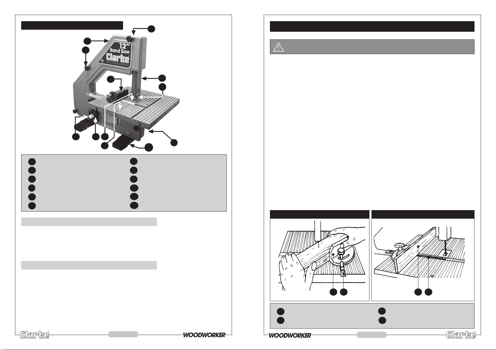
Fig. (1) Main Components
8
OPERATION
1
2
3
5 6
7
4
1 Front Cover
2 Front Cover Securing Knob (x4)
3 Rip Fence/ Mitre Gauge
4 Table Set Screw
5 Control Panel (ON/OFF)
6 Speed Control Knob
7 Table Insert
8 Blade Tensioning Screw
9 Blade Guard
10
11
12
9
10
12
Upper Blade Guide
Dust Extraction Port
Feet
11
(1) Attach the Feet (Ref: fig 1)
1. Unscrew the fours securing knobs (2) and remove the front cover. (see WARNING above)
2. Attach the feet (12) to the underside of the machine using the nuts and screws
supplied, two for each foot (13, Fig.2).
3. Replace the front cover.
WARNING!
Make sure the bandsaw is correctly assembled and adjusted
before use. Read and follow all safety instructions (see page 3)
• The blade supplied with the saw is suitable for general purpose cutting of hard and soft
woods . It is not suitable for cutting metals (See restrictions of use, page 3). The speed of
the bandsaw can be adjusted to suit the material by using the control knob below the
on/off switch. Use slower speeds for harder materials.
• A dust extractor may be used during use. Simply connect a suitable hose (not supplied),
from the dust extractor, to the dust extractor port (23, Fig.3). Dust Extractors are available
from your Clarke dealer.
• The saw is supplied with a mitre gauge to allow mitre cuts to be made.
Set the gauge to the desired angle, and use the guide slot in the table to
gauge with the workpiece across the table, into the blade as shown in Fig. 6 .
run the mitre
• The mitre gauge can also be used as a rip fence by placing it in the slot at right angles
to the blade. Fix it into place at the desired distance from the blade by using the
countersunk screw in the slot. When using the mitre gauge as a rip fence you may wish
to screw a suitable piece of hardwood or plywood (approximately 300 x 75 x 12 mm) to
the face of the gauge to extend its length (fig 7).
• The saw table can be tilted up to 45 degrees to allow you to cut bevels and compound
mitres. Slacken the table securing knobs, position the table to the desired angle, as
shown on the scale beneath the table, and tighten the knobs (see fig 3).
NOTE: If accurate mitres are required, check the table angle using a suitable gauge between
the table and blade. When adjusted, check to ensure the pointer is indicating the correct
angle and adjust if necessary.
Fig. (6) Using the Mitre Gauge
Figure (7) Using as a Rip Fence
(2) Attach the Table (Ref: fig 3)
1. Attach the table tilt bracket (19) to the underside of the table, using the four
screws and nuts supplied, as shown in fig. 3.
2. Remove the table insert (7, Fig. 1) and the counter sunk screw (4, Fig. 1) from the
table slot. (This set screw locks the two sides of the slot together, preventing the
table from flexing during use.)
3. Place the table into position from the motor side of the saw, taking care when
passing the blade through the slot, then secure the table using the washers and
adjusting knobs (18) supplied.
4. Replace the set screw (4, Fig. 1) , and fit the table insert (7, Fig. 1).
6
31 Mitre Gauge
32 Mitre Gauge Slot
31 32 33 34
33 Option Rip Fence Extension
34 Rip Fence Fixing Screw
11

(d) Blade Guide Adjustments (Ref: fig 5)
NOTE: These adjustment are carried out at the factory. It is not therefore necessary to check
or make readjustments before using for the first time.
These adjustments MUST be carried out periodically or whenever replacing a saw blade or
whenever blade tracking adjustment is carried out.
The lower guide is located beneath the table as shown at 17, Fig.2; The upper guide is
within the blade guard assembly shown at 18, Fig.2.
NOTE: It simplifies the procedure if the table is removed in order to gain easy access to the
lower blade guides.
1. Slacken the guide lock nuts (28) and back off the guides, so that there is clearance
between the guide and blade, and the support bearing locknut and back off the
support bearing. (Support bearings are shown at 29, Fig.5)
NOTE: This procedure would have been carried out previously if a new blade is being installed,
or if tracking has been reset.
2. Slacken the Guide Bracket securing screws (27) sufficiently to move the bracket laterally
so that the guides are positioned approximately in the centre of the blade. They must
not touch the teeth of the blade. When satisfied tighten the securing screws.
3. Screw in each guide until it makes light contact with the blade, then back off so that a
clearance of not more than 0.5mm is achieved, then tighten the locknut. An ideal
method of obtaining the correct clearance is to place a piece of paper between the
guide and blade then screw in the guide until the paper is just nipped.
4. Screw in the Blade Support Bearings (shown at 29) until they make light contact with the
back edge of the blade, then back off until a clearance of 0.5mm is obtained and
tighten the locknut.
Fig. (2) Cover Removed
18
15 18 16
14
13 Foot Securing screw (x4)
14 Control Panel (On/Off/Speed)
15 Microswitch
Fig. (3) Rear View
17
13
16 Drive Wheel
17 Lower Blade Guide
18 Motor Cover Securing Screws
Fig. (5) Blade Guides
29
28
27 Guide Bracket Securing Screws
28 Guide Lock Nuts (x4)
29 Blade Support Bearings
10
27
27
28
21
19
18
23
18 Table Securing Knobs (x2)
19 Table Tilt Bracket
20 Table Tilt Indicator (Degrees)
20
21 Table Adjusting Screw
22 Motor Cover
23 Dust Extraction Outlet
7
22

(3) Attach the Bandsaw to a Workbench
Fix the bandsaw to a suitable Workbench using screws or bolts (not supplied), through the
holes in the feet with washers under the screw heads. Do not overtighten the securing screws.
1. Remove the table by fully unscrewing the two securing knobs, then slacken off all upper
and lower blade guides as described under ‘Blade Guide Adjustments’ on page 10.
2. Correctly tension the blade as described under ‘Blade Tension’ on page 8.
3. Remove the front cover in order to gain access to the blade and wheels.
Adjustments
IMPORTANT: To achieve the best performance and maintain the maximum level of safety,
certain adjustments must be made, BEFORE use.
WARNING! The machine MUST be disconnected from the mains supply
before any adjustments are made.
(a) Table Adjustment (Ref: Fig. 3)
The screw (21) allows the table to be adjusted so that it is square to the blade.
With the table securing knobs (18) slackened, slide a small square across the table so that
it contacts the side of the blade, then check to ensure the angle made is a right angle. If
necessary turn the adjuster screw (21) clockwise or anticlockwise, whilst maintaining a slight
pressure on the adjusting screw side of the table top, until the table is at 90 degrees to the
blade. Tighten the table securing knobs, then check the table angle Indictor (20). If
necessary, reposition the pointer so that it points to zero on the scale.
(b) Blade Tension (Ref: fig 4)
1. Slacken the blade tension locking knob (25) one full turn.
2. Adjust the blade tension Hex. socket head adjuster screw (24) a little at a time:
clockwise to tighten increase tension, anticlockwise to decrease.
3. When correct tension has been achieved tighten the blade tension locking knob (25).
The blade needs to be tight enough to give a straight cut without allowing it to wander
or slip or lose its tracking, but must not be so tight that it is rigid, there must be a certain
degree of flexibility.
A few minutes using the machine will allow you to get a feel for correct blade tension.
If the saw is not to be used for some time we recommend that you release the tension on
the blade. REMEMBER therefore to ALWAYS check blade tension before use.
WARNING!
Disconnect the bandsaw from the mains supply before
removing the front cover.
4. Carefully turn the driving wheel (16, Fig. 2) by hand to check blade tracking, taking
care to keep fingers well clear of the blade, and not trapping them between the blade
and the wheel. The blade must run true, as close to the centre of the rim of each wheel
as possible.
5. Adjust the tracking by turning the Hex. socket head adjuster screw (26) a little at a
time....clockwise to move the blade inwards towards the motor side of the machine,
and anticlockwise to move it outwards. Turn the driving wheel by hand as you turn the
adjuster screw.
6. Check blade tension once again after completing the tracking adjustment and adjust
if necessary.
7. Replace the front cover (1), then adjust the Blade Guides as described in the following
paragraphs.
Fig, (4)
24
25
23
26
(c) Blade Tracking (Ref: fig 4)
NOTE: This adjustment is carried out at the factory. It is not therefore necessary to check or
readjust before use for the first time.
The adjustment MUST be made whenever replacing a saw blade or if the saw blade runs off
the wheels.
The blade must ‘track’ correctly otherwise it will continually run off the drive and idler wheels.
The blade should run in the middle of the wheels rims, and the procedure for checking and
adjusting is as follows:
8
23 Blade Guard Locking Knob
24 Blade Tension Adjuster Screw
25 Blade Tension Locking Knob
26 Blade Tracking Adjust Screw
9
 Loading...