

Page 1
WARNING: Read these instructions before using the product
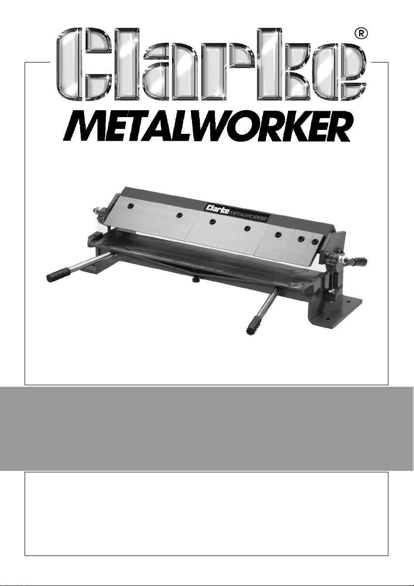
BOX & PAN FOLDER
MODEL NO: CBPF1
PART NO: 7627906
OPERATION & MAINTENANCE
INSTRUCTIONS
ORIGINAL INSTRUCTIONS GC09/23
Page 2
INTRODUCTION
Thank you for purchasing this CLARKE product. Before attempting to use it
please read this manual and carefully follow all instructions given. In doing so
you will ensure the safety of yourself and that of others around you, and you
can also look forward to the product giving you long and satisfactory service.
Ensure the product suffered no damage during transit and that all items are
present. Should any loss or damage become apparent, please contact your
CLARKE dealer immediately.
PRODUCT SPECIFICATIONS
Dimensions L x W x H 760 x 230 x 220mm Length with handles = 460mm
Net Weight 27kg
Clamping finger
dimensions
Max Bending
Capacity Thickness -1.2mm Width 730mm
GUARANTEE
This CLARKE product is guaranteed against faulty manufacture for a period of
12 months from the date of purchase. Please keep your receipt as proof of
purchase.
This guarantee is invalid if the product is found to have been abused or
tampered with in any way, or not used for the purpose for which it was
intended. Faulty goods should be returned to their place of purchase, no
product can be returned to us without prior permission.
This guarantee does not effect your statutory rights.
25mm (1”)
51mm (2”)
77mm (3”)
203mm (8”)
255mm (10”)
Angle - 0-90
o
ENVIRONMENTAL PROTECTION
Recycle unwanted materials instead of disposing of them as waste.
All unwanted accessories and packaging should be sorted and
taken to a recycling centre for disposal in a manner which is
compatible with the environment.
2
Parts & Service: 020 8988 7400 / E-mail: [email protected] or [email protected]
Page 3

SAFETY PRECAUTIONS
As with all tools and workshop equipment it is necessary to exercise caution
when it is put to use, being aware of any associated or inherent dangers.
• Due to the weight of the product, the help of an assistant may be
beneficial during unpacking and mounting.
• ALWAYS operate on a suitably strong bench with adequate light.
• This equipment must be firmly secured to a firm and level bench using
suitable bolts (not supplied).
• Leave adequate working space around the equipment for safer and
convenient operation.
• ALWAYS check for signs of structural damage before starting work. DO NOT
use if damage is found. Have repairs made only by a CLARKE service
centre.
• ALWAYS ensure the workpiece is secure and properly positioned before
applying pressure.
• ALWAYS keep hands and fingers away from moving parts that may pinch.
• NEVER use extension tubes to increase the length of the handles. Excessive
effort can cause damage and/or accidents.
• NEVER attempt to bend materials which exceed the sizes stated above.
Failure to heed these warnings may result in damage to the equipment or
personal injury.
3
Parts & Service: 020 8988 7400 / E-mail: [email protected] or [email protected]
Page 4
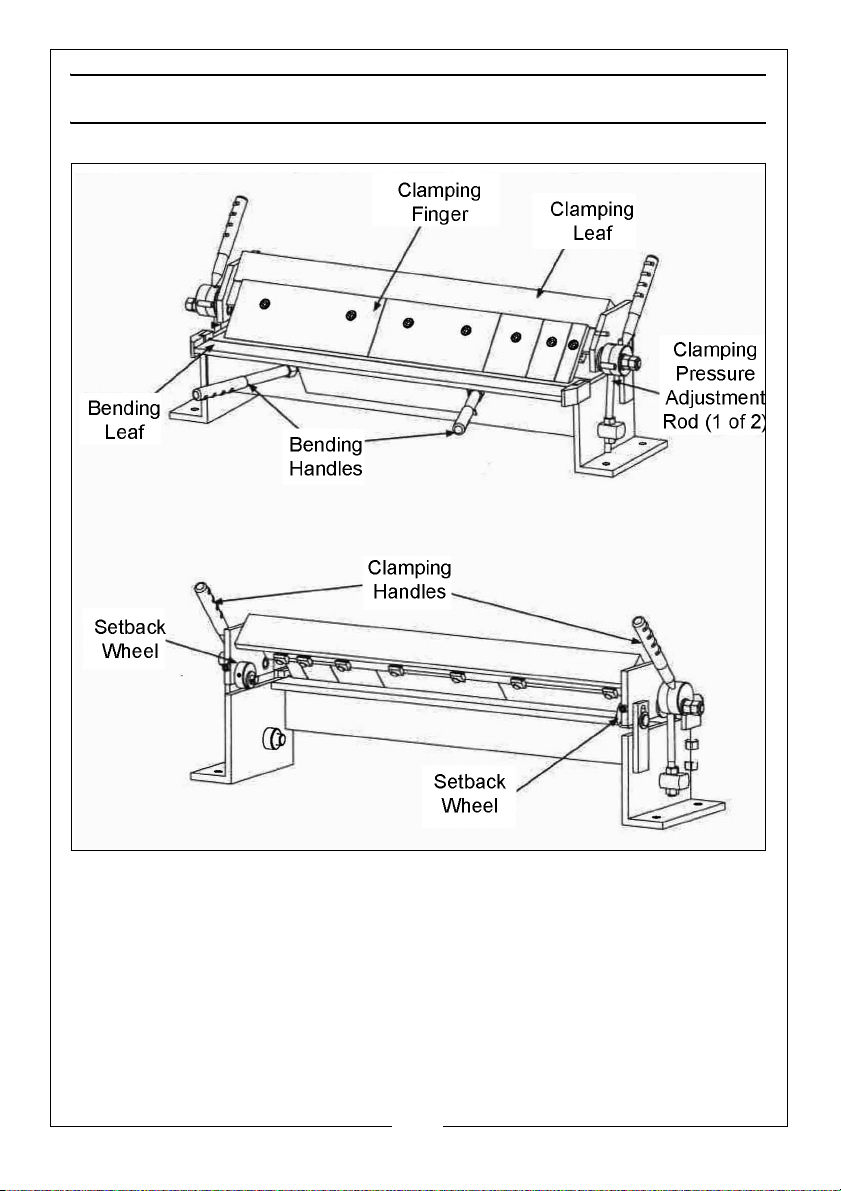
PARTS IDENTIFICATION
CONTENTS
• 1 x Box & Pan Folder
• 2 x Handles
• 1 x 17mm /19mm spanner
• 1 x 5mm hex key
• 1 x 8mm hex key
If any items are missing contact your Clarke dealer.
4
Parts & Service: 020 8988 7400 / E-mail: [email protected] or [email protected]
Page 5
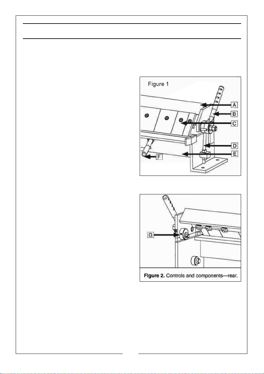
WORKING COMPONENTS
Refer to the following figures and descriptions to become familiar with the
components of this device. Understanding these items and how they work will
help you understand the rest of the manual and minimize your risk of injury
when using this product.
A: Clamping Leaf: Holds and positions
the clamping fingers.
B. Clamping Handle (pair): Used to
raise and lower the clamping leaf.
C. Clamping Finger: Holds the
workpiece in place while the bending
block produces the bend. Fingers can
be individually removed or
repositioned to allow clearance for the
workpiece.
D: Clamping Pressure Adjustment Rod
(pair): Move up or down to set the
cIamping pressure on the workpiece
according to the workpiece gauge.
Lock the rod in place with jam nuts.
E: Bending Leaf: Swivels up to bend the
workpiece.
F: Bending Handle (pair): Use to raise
the bending leaf and produce a bend
in the workpiece.
G. Setback Wheel (pair): Use to adjust
the distance between the clamping
fingers and the bending block. Moves
the clamping leaf forward and
backward.
5
Parts & Service: 020 8988 7400 / E-mail: [email protected] or [email protected]
Page 6

PREPARATION/CLEANING
The unpainted surfaces of your machine are coated with a heavy-duty rust
preventative that prevents corrosion during shipment and storage. This rust
preventative works extremely well but it will take a little time to clean.
Be patient and clean the machine thoroughly. The time you spend doing this
now will give you a better appreciation for the proper care of your machine's
unpainted surfaces.
There are many ways to remove this rust preventative but the following steps
work well in a wide variety of situations. Always follow the manufacturer's
instructions with any cleaning product you use and make sure you work in a
well-ventilated area to minimize exposure to toxic fumes.
Before cleaning, gather the following:
• Disposable rags
• Cleaner/degreaser
• Safety glasses &disposable gloves
• Plastic paint scraper (optional)
Basic steps for removing rust preventative
1. Coat the rust preventative with a liberal amount of cleaner/degreaser,
then let it soak for 5-10 minutes.
2. Wipe the surfaces. If your degreaser is effective, the rust preventative will
wipe off easily. If you have a plastic paint scraper, scrape off as much as
you can first, then wipe off the rest with the rag.
3. Repeat Steps 2-3 as necessary until clean, then coat all unpainted surfaces
with a quality metal protectant to prevent rust such as light oil.
6
Parts & Service: 020 8988 7400 / E-mail: [email protected] or [email protected]
Page 7
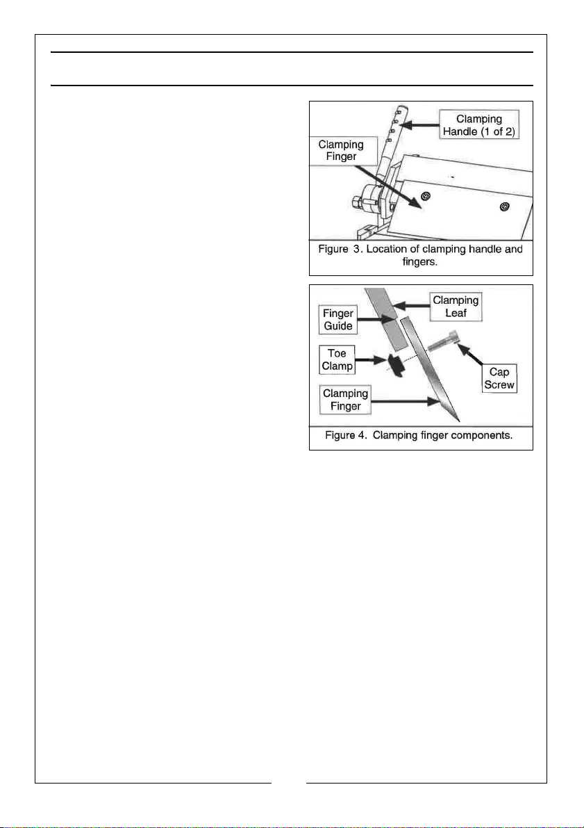
CLEANING THE FINGERS
Although rust preventative was applied
only to the visible surfaces of the
clamping fingers (see Figure 3), some
may have worked in between and
underneath them. We recommend you
remove all clamping fingers and
thoroughly clean them.
To remove the clamping fingers, move
the clamping handles toward back of
the machine to raise the clamping leaf,
then loosen the cap screws and
remove the clamping fingers and toe
clamps (see Figure 4).
After all the fingers have been
cleaned, coat them liberally with a
metal protectant and clean the finger guide on the clamping leaf.
Place the fingers along the guide on the clamping leaf, align the toe clamps
to catch the bottom of the clamping leaf and tighten the cap screws enough
so the fingers will not fall off. When done, make sure fingers are properly
aligned (refer to Aligning Fingers on page 11).
7
Parts & Service: 020 8988 7400 / E-mail: [email protected] or [email protected]
Page 8
BENCH MOUNTING
WORKBENCH LOAD
Refer to the product specification on
page 2 for the weight and footprint
specifications of your machine. Some
workbenches may require additional
reinforcement to support the weight of
the machine and workpiece materials.
PLACEMENT LOCATION
Consider anticipated workpiece sizes
and additional space needed for
auxiliary stands, work tables, or other
machinery when establishing a
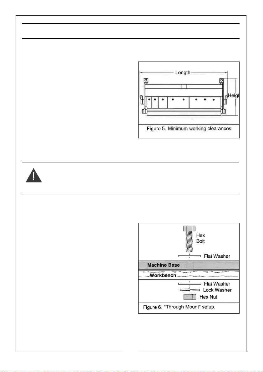
location for this machine in the workshop. Below is the minimum amount of
space needed for the machine.
WARNING: LIFTING HEAVY MACHINERY OR PARTS WITHOUT PROPER
ASSISTANCE OR EQUIPMENT MAY RESULT IN STRAINS, BACK INJURIES,
CRUSHING INJURIES OR PROPERTY DAMAGE.
The base of this machine has mounting holes that allow it to be fastened to a
workbench or other mounting surface to prevent it from moving during
operation and causing accidental injury or damage.
The strongest mounting option is a
"Through Mount" (see example below)
where holes are drilled all the way
through the workbench-and hex bolts,
washers, and hex nuts are used to
secure the machine in place.
• Number of mounting holes = 4
• Diameter of mounting hardware
needed. 3/8”.
8
Parts & Service: 020 8988 7400 / E-mail: [email protected] or [email protected]
Page 9
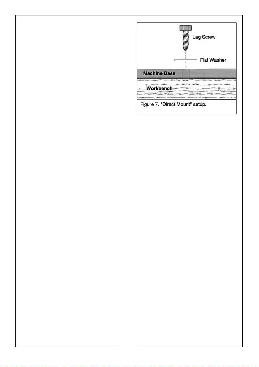
Another option is a "direct mount" (see
example) where the machine is
secured directly to the workbench with
lag screws and washers.
9
Parts & Service: 020 8988 7400 / E-mail: [email protected] or [email protected]
Page 10
SPACING THE FINGERS
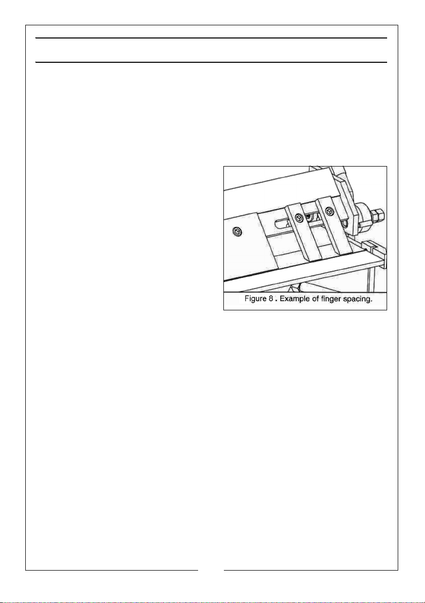
The clamping fingers can be spaced apart for clearance when making pans
or boxes. This requires removing one or more of the fingers so that you can
space the others to match the inside width of your pan or box.
TOOLS NEEDED
Hex wrench 8mm
TO SPACE CLAMPING FINGERS:
1. Loosen the cap screws from each
finger you need to remove.
2. Remove the fingers and toe clamps
from the clamping leaf, as shown in
Figure 8, and set them aside.
NOTE: You may need to mix and
match finger widths to match
the inside width of your pan or
box.
3. Align the remaining fingers and
tighten the cap screws.
10
Parts & Service: 020 8988 7400 / E-mail: [email protected] or [email protected]
Page 11
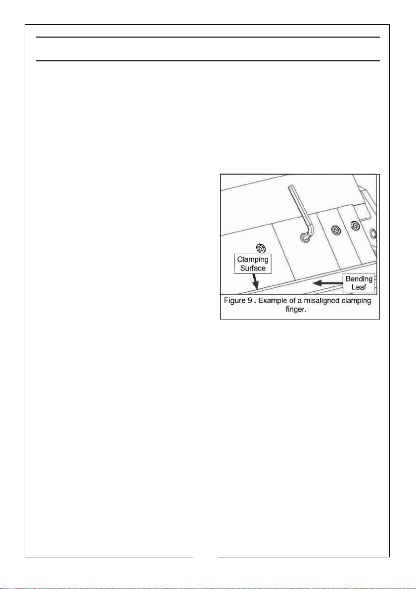
ALIGNING THE CLAMPING FINGERS
To help ensure the bend is even along its length, the clamping fingers must be
parallel with the clamping surface and bending block.
TOOLS NEEDED
Hex wrench 8mm
TO ALIGN CLAMPING FINGERS:
1. Lower the clamping leaf until the clamping fingers are just touch the
clamping surface (see Figure 9)
2. Look closely along the bottom
edge of each finger to determine if
any are out of alignment with the
clamping surface and bending
leaf, as shown in Figure 9.
3. Loosen the cap screw on a
misaligned finger just enough to
move it up or down.
4. Align the finger parallel with the
clamping surface and bending
block and then tighten the cap
screw.
11
Parts & Service: 020 8988 7400 / E-mail: [email protected] or [email protected]
Page 12
ADJUSTING SETBACK
NOTE: Include the thickness of folded edges or joints when determining
the proper setback or the equipment may be damaged.
Before you begin any bending operation, consider the differences of sheet
metal gauges when trying to achieve either sharp or rounded bends and
allow for the differences by adjusting the setback.
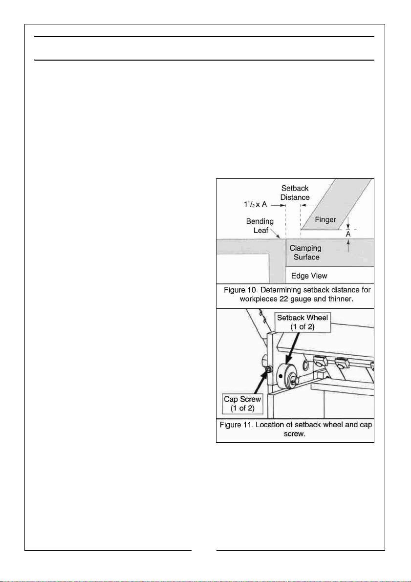
Setback is the distance from the forward edge of the fingers to the edge of
the bending leaf, as shown in Figure 10. The setback distance is determined by
the gauge of the workpiece material and the desired radius of the bend.
Setback is normally adjusted 150% the
thickness of 22 gauge and thinner
workpieces, and 200% the thickness of
a workpieces thicker than 22 gauge.
TO ADJUST SETBACK
1. Determine setback required for
bend.
2. Raise the clamping fingers about
12mm off the clamping surface.
3. Loosen the cap screws that secure
the setback wheels (see Figure 11).
4. Rotate both setback wheels until
the desired setback distance is
achieved.
NOTE: Setback wheels are eccentric.
Turning them one full turn will
bring the clamping leaf back
to its original position.
If you find it hard to turn the setback
wheels with your fingers, insert a hex
wrench into the holes on the edges of
the wheels to gain leverage.
5. Lower the clamping fingers onto the clamping surface and check the
setback distance.
6. If necessary, repeat Steps 1-4 until the desired setback is achieved.
7. Check the finger alignment (refer to Aligning Fingers on Page 11).
12
Parts & Service: 020 8988 7400 / E-mail: [email protected] or [email protected]
Page 13
ADJUSTING CLAMPING PRESSURE
Clamping pressure must be properly
adjusted for different workpiece
thicknesses. The ideal pressure will have
medium resistance at the clamping
handles and will lock the workpiece
into position easily.
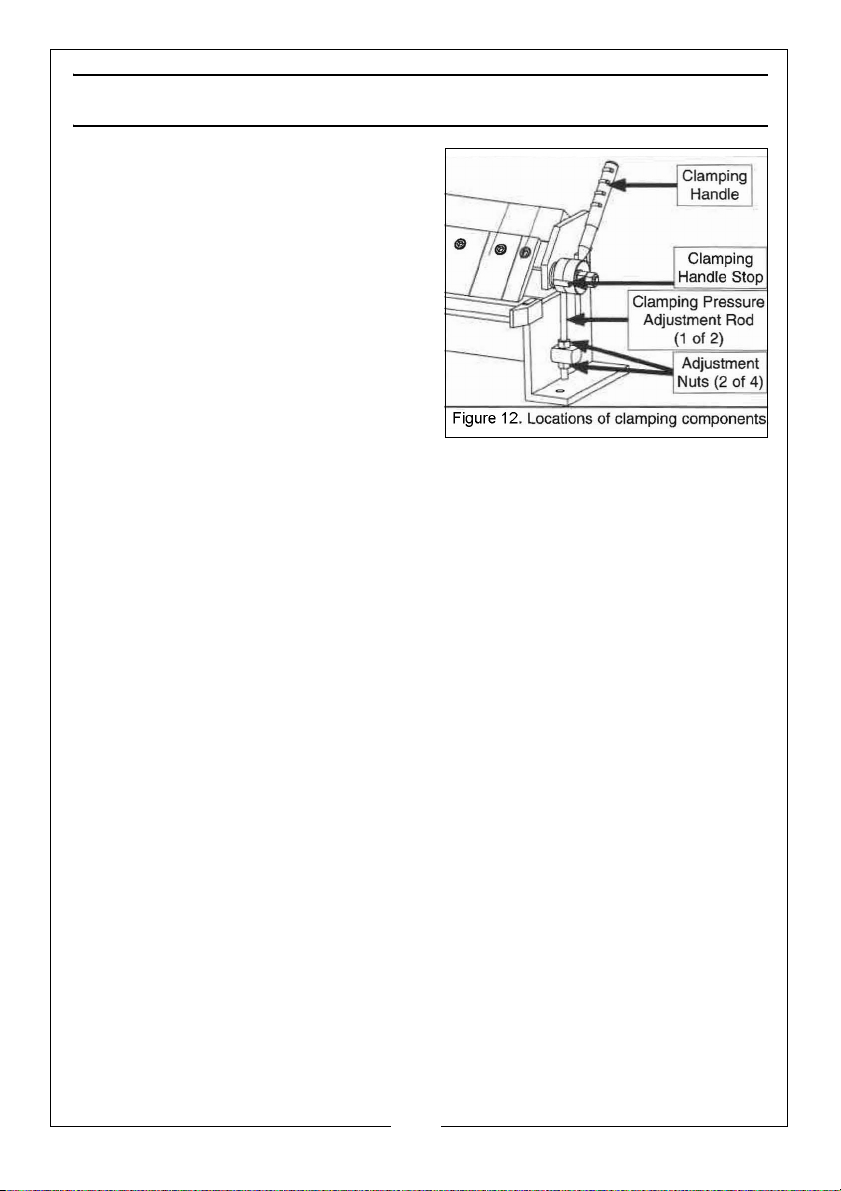
Pressure is adjusted by rotating the
adjustment nuts on the clamping
pressure adjustment rods (see Figure
12). These are located on both ends of
the machine.
TOOLS NEEDED
Open ended wrench 17/19mm
1. Lower the clamping leaf so the clamping fingers just touch the workpiece.
It is best if the workpiece used in this procedure is same width as the machine.
If not, place two pieces of metal of the same thickness as the workpiece on
each end of machine.
NOTE: If the clamping handles are at 10 o'clock (viewed from the right
end) and 2 o'clock (viewed from left end) position, then the
clamping pressure is suitable for the workpiece. Proceed to Step
4.
NOTE: If the clamping handles are not at 10 o'clock (viewed from right
end of brake) and 2 o'clock (viewed from left end of brake)
position, then the clamping pressure is not suitable for the
workpiece. Proceed to Step 2.
2. Loosen the adjustment nuts (see Figure 12) and turn both sets up or down
until the clamping handles are in the 10 and 2 o'clock position when the
clamping fingers just touch the workpiece.
3. Tighten the adjustment nuts to secure in position.
4. Make sure the clamping pressure is even on both ends of the machine by
raising one end and testing the clamping action of other end. The
clamping action should be same on both ends.
5. If necessary, repeat Steps 1-4 until proper clamping pressure is achieved.
NOTE: Proper clamping pressure is achieved when the clamping handle
snaps (or locks) into position against the handle stop (see Figure
12).
13
Parts & Service: 020 8988 7400 / E-mail: [email protected] or [email protected]
Page 14
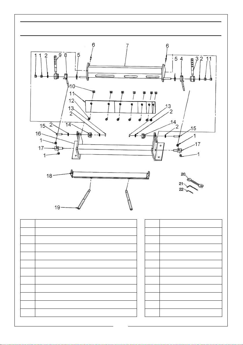
COMPONENT PARTS
Part Description Part Description
1 Hex nut M12 12 Cap screw M10
2 Flat washer 12mm 13 Roll Pin
3 Clamping handle (right) 14 Setback Wheel
4 Clamping pressure adjusting rod (right) 15 Pivot shaft
5 Flat washer 12mm 16 Stand
6 Cap screw M6 17 Swivel rod block
7 Clamping leaf 18 Bending leaf
8 Clamping pressure adjusting rod (left) 19 Bending handle
9 Clamping handle (left) 20 Wrench 17 x 19mm
10 Toe clamp M10 21 Hex wrench 8mm
11 Clamping finger 22 Hex wrench 8mm
14
Parts & Service: 020 8988 7400 / E-mail: [email protected] or [email protected]
Page 15
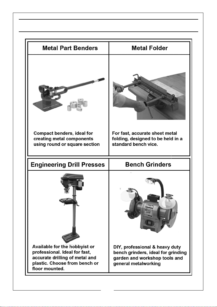
SHEET METALWORKING FROM THE CLARKE RANGE
15
Parts & Service: 020 8988 7400 / E-mail: [email protected] or [email protected]
Page 16

 Loading...