

Page 1
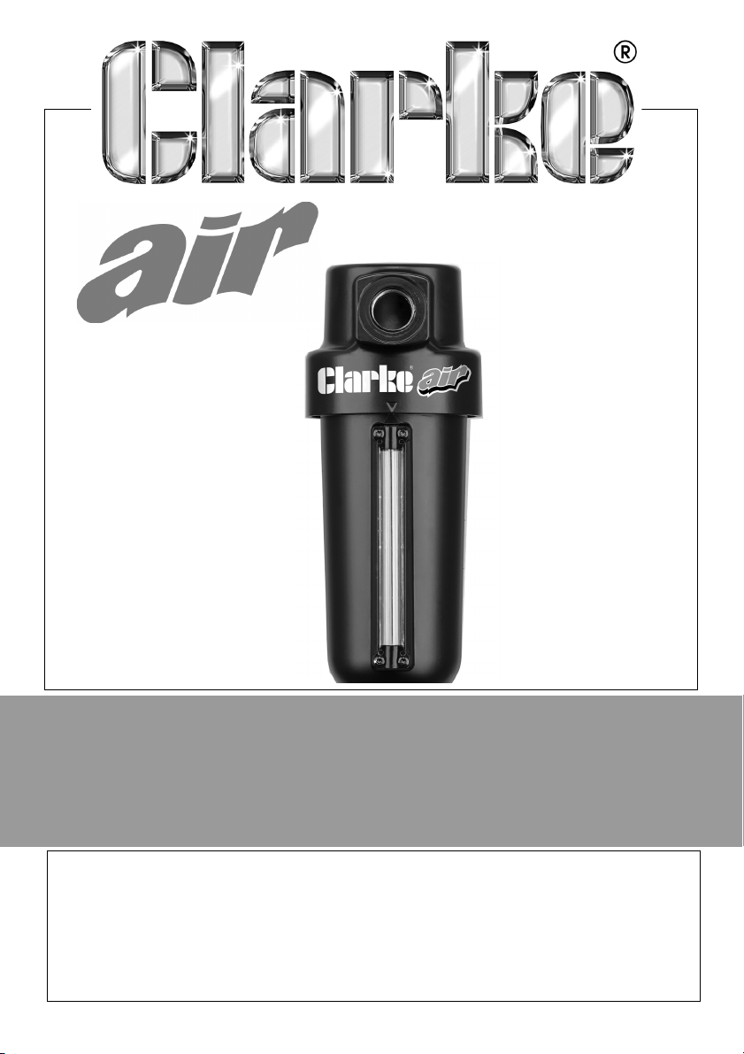
AIRLINE FILTER
MODEL NO: CAT187
PART NO: 3120504
OPERATING & MAINTENANCE
INSTRUCTIONS
ORIGINAL INSTRUCTIONS GC0122 - Rev 1
Page 2
INTRODUCTION
Thank you for purchasing this CLARKE Airline Filter.
Before attempting to use this product, please read this manual thoroughly and
follow the instructions carefully. In doing so you will ensure the safety of yourself
and that of others around you, and you can look forward to your purchase
giving you long and satisfactory service.
Your filter has been designed to give long and trouble free service. If, however,
having followed the instructions in this booklet carefully, you encounter
problems, take the unit to your local CLARKE dealer.
SPECIFICATIONS
CAT187
Dimensions (D x W x H) 110 x 120 x 302 mm
Air Inlet /Outlet Size 3/4“BSP (female)
Max Flow 325 CFM
Max Inlet Pressure 250 psi
Element Micron Rating
Max working Temperature 175 deg F
5
μ
GENERAL SAFETY RULES
CAUTION: FAILURE TO FOLLOW THESE PRECAUTIONS COULD RESULT IN
PERSONAL INJURY, AND/OR DAMAGE TO PROPERTY.
WORK ENVIRONMENT
1. Keep the work area clean and tidy.
2. Dress appropriately - do not wear loose clothing or jewellery. Tie long hair
out of the way.
3. Keep children and visitors away - do not let children handle the tools.
4. Do not operate air tools where there are flammable liquids or gases.
2
Parts & Service: 020 8988 7400 / E-mail: [email protected] or [email protected]
Page 3
USE OF AIRLINE EQUIPMENT
1. Stay alert and use common sense - do not operate an air tool when you
are tired or under the influence of alcohol, drugs or medication.
2. Do not overreach - Keep proper footing and balance at all times.
3. Never use oxygen, CO
source of power for air tools.
4. Do not exceed the maximum pressure for the airline component stated in
the specification.
5. Check airline hoses for leaks or worn condition before use and ensure that
all connections are secure.
6. Keep the air supply hose away from heat, oil and sharp edges.
7. Avoid damaging the component for example by applying excessive force
of any kind.
8. Always maintain the air tool with care. Keep it clean for the best and safest
performance.
, combustible gases or any type of bottled gas as a
2
COMPRESSED AIRLINE REQUIREMENTS
WARNING: COMPRESSED AIR CAN BE DANGEROUS. ENSURE THAT YOU
ARE FAMILIAR WITH ALL PRECAUTIONS RELATING TO THE USE OF
COMPRESSORS AND COMPRESSED AIR SUPPLY.
• Use only clean, dry, regulated compressed air as a power source.
• Air compressors must comply with the appropriate European
Community Safety Directives.
• A build-up of moisture in the air compressor will accelerate wear
and corrosion in the air tool. Ensure any moisture is drained from the
compressor daily and the airline filter is kept clean.
• If an unusually long air hose is required, (over 8 metres), the line
pressure or the hose inside diameter may need to be increased.
• The air hose must be rated at least 150% of the maximum operating
pressure of the air tool.
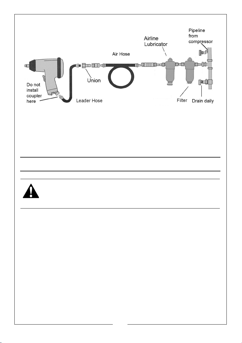
• A typical air line layout is shown below. If an automatic in-line filter/
regulator is used it will keep the tool in good condition. The lubricator
should be adjusted to approx 2 drops per minute and SAE 10 oil
should be used.
3
Parts & Service: 020 8988 7400 / E-mail: [email protected] or [email protected]
Page 4
.
• Never exceed the maximum operating pressure for the air tool.
Ensure that air pressure does not exceed that stated in the
specification for the tool when running. Higher pressures and
contaminated air will shorten the life of the air tool due to faster
wear and is a possible safety hazard.
INSTALLATION
WARNING: COMPRESSED AIR CAN BE DANGEROUS. ENSURE THAT YOU
ARE FAMILIAR WITH ALL PRECAUTIONS RELATING TO THE USE OF AIR
COMPRESSORS AND COMPRESSED AIR SYSTEMS.
1. Ensure the compressor is turned off. Before using the airline, drain water
from the air reservoir at the compressor.
• The filter should be installed with reasonable accessibility for service
whenever possible.
2. Keep pipe or tubing lengths to a minimum with the inside clean and free of
dirt. Pipe joint compound should be used sparingly and applied only to the
male pipe — never into the female port.
3. Take care using PTFE tape to seal pipe joints — pieces have a tendency to
break off and lodge inside the unit, possibly causing malfunction.
4. Install the filter so that air flows as marked by the arrow on the filter body.
5. Installation should be downstream of the regulator but upstream of any
lubricator.
4
Parts & Service: 020 8988 7400 / E-mail: [email protected] or [email protected]
Page 5
6. Install the filter vertically with the bowl drain mechanism at the bottom.
ensuring there is sufficient free space below the filter for future access.
7. Remove the blanking plugs from the connection ports and connect to the
supply and delivery hoses.
8. A drain hose can be screwed to the drain port or the filter bowl drained
manually.
9. Your filter is now ready for use.
USE AND CARE IN SERVICE
1. Let the filter run with the air supply on. Ensure that the pressure to the air
inlet of the filter from air line does not exceed the maximum pressure
specified.
2. The filter is equipped with a manual drain valve. Turn the drain valve to
expel accumulated liquid inside the bowl whenever necessary and always
keep the liquid below the filter element.
3. The filter element should be replaced when the pressure drop across the
element exceeds 15 psi. When an excessive pressure drop across a
saturated but uncontaminated element occurs, it may indicate that the
tool being operated exceeds the maximum flow rate (CFM) of the filter
(See Specification). Refer to the maximum flow rate of your filter and make
sure that the required CFM of the tool is within the maximum flow rate of
your filter for best tool operation.
4. Check the visual indicator and drain the filter bowl when required using the
drain tap. A hose may be connected to drain the condensate into a
suitable container.
MAINTENANCE
DISASSEMBLY
1. The filter can be disassembled without removal from the air line.
2. Shut off inlet pressure. Reduce pressure in the inlet and outlet lines to zero.
3. Unscrew the bowl.
4. Disassemble in accordance with the parts illustrated on page 7. Do not
remove the drain unless replacement is necessary. Remove and replace
only when the drain malfunctions or is being replaced with an optional
automatic drain.
5
Parts & Service: 020 8988 7400 / E-mail: [email protected] or [email protected]
Page 6
CLEANING
1. Clean all parts with warm water and soap.
CAUTION: Some components may be made from polycarbonate which can
be severely damaged if it comes into contact with some chemicals. These
include acetone, benzene, carbon tetrachloride, ethylene di-chloride,
gasolene or synthetic fire resistant lubricants.
2. Rinse and dry the parts. Blow out internal passages in the body with clean,
dry, compressed air. Blow air through the filter element from inside to
outside to remove surface contaminants.
3. Inspect all parts and replace any found to be damaged.
ASSEMBLY
1. Lubricate the O-rings, the portion of the manual drain body that contacts
the bowl, and the hole in the manual drain body that accommodates the
stem of the drain valve with O-ring grease.
2. Assemble the filter as shown on page 7. Place the O-ring on the louver,
then press into place in the body. Screw the baffle on the center post until
contact is made with the filter element, then tighten an additional 1/4 turn.
3. Assemble the Sight glass kit (Ref. No.6) to the bowl. Apply a gentle
clamping force to the upper and lower sigh glass brackets to pull the
brackets together, then tighten the screws per the table below.
4. Tighten these parts listed in Torque Settings table.
5. Twist the bowl into the body until the arrowhead is in line with or to the right
of the arrowhead on the body.
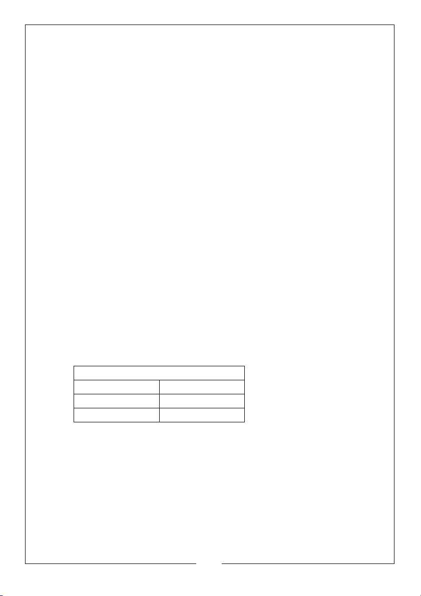
Torque Settings
Part Inch Pounds (N-m)
Screw 8 to 10 (0.9 to 1.13)
Nut 20 to 25 (2.3 to 2.8)
ACCESSORIES
A wide range of accessories is available including filter/regulators, lubricators,
high-pressure hoses (5 to 50 metres) etc.
Contact your CLARKE dealer for further information or CLARKE International
Service Department.
6
Parts & Service: 020 8988 7400 / E-mail: [email protected] or [email protected]
Page 7
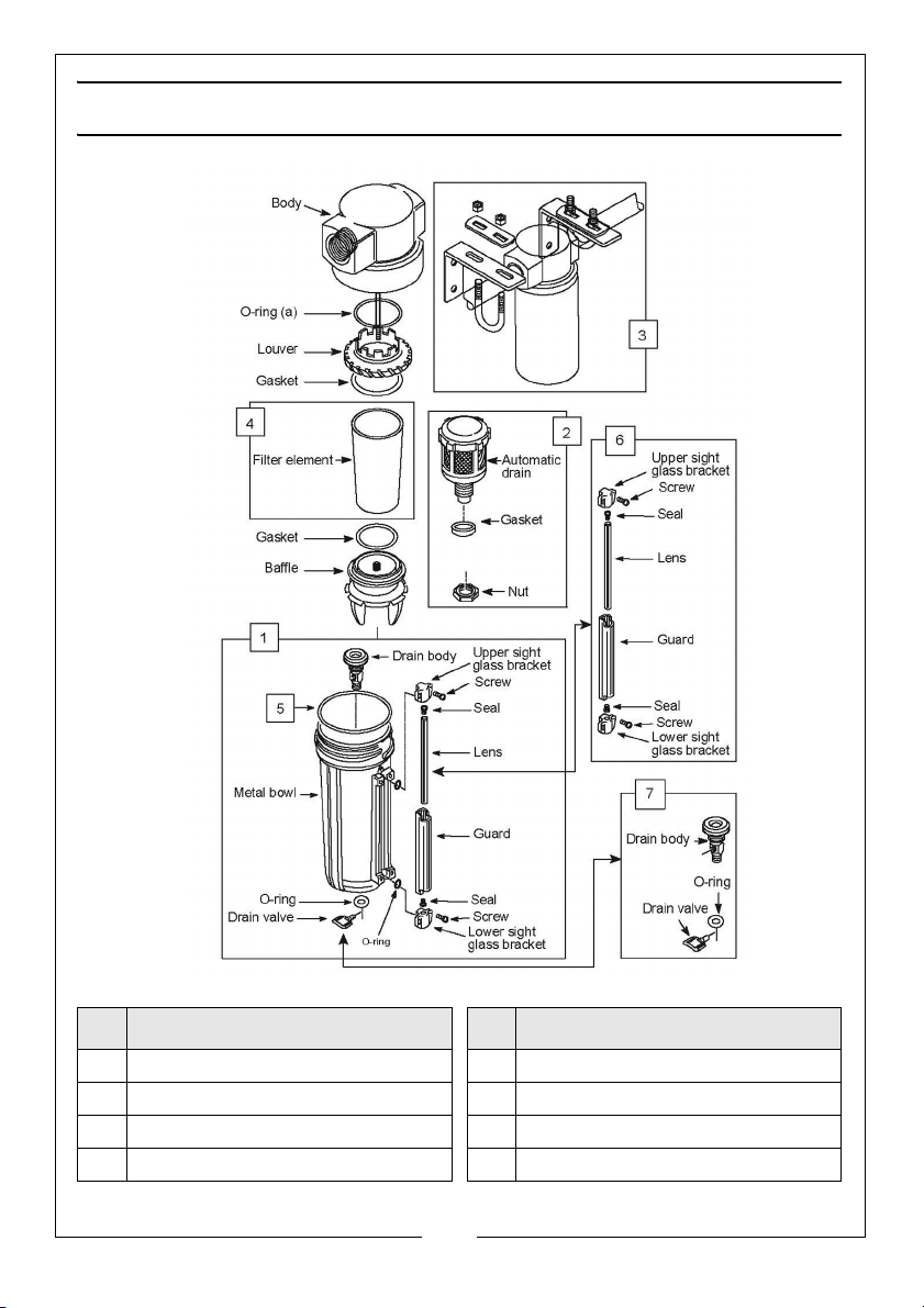
PARTS LIST & DIAGRAM
No Description No Description
1 Metal bowl and O-ring 5 O-Ring
2 Auto drain kit 6 Sight glass kit
3 Wall bracket 7 Manual drain kit
4 5 micron filter element
7
Parts & Service: 020 8988 7400 / E-mail: [email protected] or [email protected]
Page 8
 Loading...