

Page 1
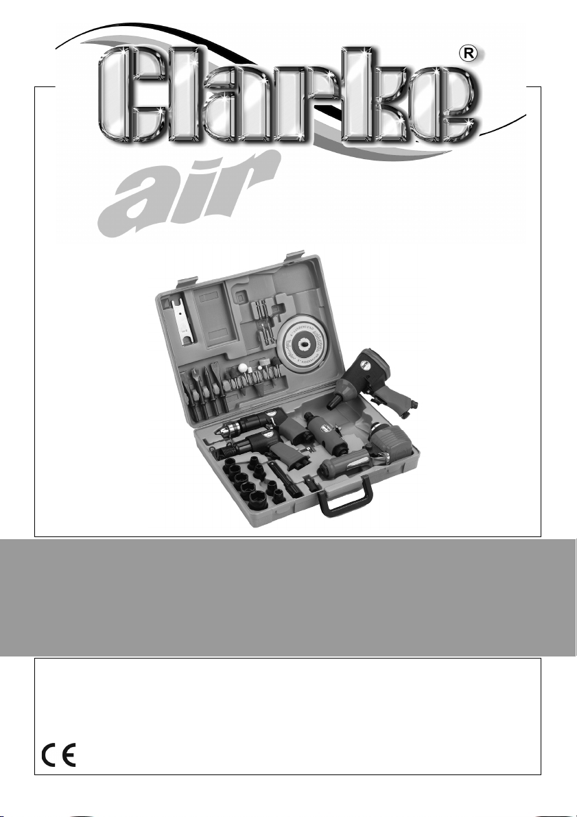
43 PIECE AIR TOOL KIT
MODEL NO: CAT120
PART NO: 3110876
OPERATION & MAINTENANCE
INSTRUCTIONS
ORIGINAL INSTRUCTIONS GC 0520 - ISS 3
Page 2

INTRODUCTION
Thank you for purchasing this CLARKE product.
Before attempting to use this product, please read this manual thoroughly and
follow the instructions carefully. In doing so you will ensure the safety of yourself
and that of others around you, and you can look forward to your purchase
giving you long and satisfactory service.
GUARANTEE
This product is guaranteed against faulty manufacture for a period of 12
months from the date of purchase. Please keep your receipt which will be
required as proof of purchase.
This guarantee is invalid if the product is found to have been abused or
tampered with in any way, or not used for the purpose for which it was
intended.
Faulty goods should be returned to their place of purchase, no product can
be returned to us without prior permission.
This guarantee does not effect your statutory rights.
ENVIRONMENTAL PROTECTION
Recycle unwanted materials instead of disposing of them as
waste. All tools, accessories and packaging should be sorted,
taken to a recycling centre and disposed of in a manner which is
compatible with the environment.
2
Parts & Service: 020 8988 7400 / E-mail: [email protected] or [email protected]
Page 3

TABLE OF CONTENTS
INTRODUCTION ......................................................................... 2
GUARANTEE ............................................................................... 2
ENVIRONMENTAL PROTECTION ................................................ 2
TABLE OF CONTENTS ................................................................. 3
GENERAL SAFETY RULES ............................................................ 4
LIST OF CONTENTS ..................................................................... 6
Accessories ...................................................................................................... 6
AIR SUPPLY ................................................................................. 7
Recommended Air Supply Connection ...................................................... 7
THE IMPACT WRENCH ............................................................... 8
Before Use ........................................................................................................ 9
Using The Forward/reverse Button ................................................................ 10
Fitting the Impact Socket ............................................................................... 10
Adjusting the Power ....................................................................................... 11
Operating The Impact Wrench ..................................................................... 11
Disconnecting the air supply ......................................................................... 11
THE DUAL ACTION SANDER ...................................................... 12
Before Use ........................................................................................................ 13
Fitting The backing pad ................................................................................. 13
Fitting The Sanding Sheet ............................................................................... 13
Adjusting The Speed ....................................................................................... 14
Using The Sander ............................................................................................. 14
THE CHIPPING HAMMER ........................................................... 15
Before Use ........................................................................................................ 16
Fitting the chisel .............................................................................................. 16
Adjusting the force ......................................................................................... 17
Using the Chipping Hammer ......................................................................... 17
THE DIE GRINDER ....................................................................... 18
Before Use ........................................................................................................ 19
Collets ............................................................................................................... 19
Fitting the grinding point or stone ................................................................. 20
Using the Die Grinder ...................................................................................... 20
THE REVERSIBLE DRILL ............................................................... 21
Before Use ........................................................................................................ 22
Inserting/Removing the Drill Bit ...................................................................... 22
Direction Control Switch ................................................................................ 23
Using The Reversible Drill ................................................................................ 23
AFTER USE .................................................................................. 24
Disconnecting The Air Supply ........................................................................ 24
Storage ............................................................................................................. 24
MAINTENANCE .......................................................................... 25
SPECIFICATIONS - GENERAL ................................................... 26
SPECIFICATIONS - MODEL SPECIFIC ........................................ 27
VIBRATION EMISSIONS ............................................................. 28
DECLARATION OF CONFORMITY ............................................. 30
NOTES ........................................................................................ 31
3
Parts & Service: 020 8988 7400 / E-mail: [email protected] or [email protected]
Page 4

GENERAL SAFETY RULES
CAUTION: FAILURE TO FOLLOW THESE PRECAUTIONS COULD RESULT IN
PERSONAL INJURY, AND/OR DAMAGE TO PROPERTY.
CAUTION: THESE RULES APPLY TO ALL TOOLS IN THIS KIT.
WORK ENVIRONMENT
1. Keep the work area clean and tidy.
2. Dress appropriately - Do not wear loose clothing or jewellery. Tie long hair
out of the way.
3. Keep children and visitors away - Do not let children handle the tool.
4. Do not operate the tool where there are flammable liquids or gases.
5. Keep the air supply hose away from heat, oil and sharp edges.
6. Do not fit the tool to any stand or clamping device that may damage the
tool.
USE
1. Stay alert and use common sense - Do not operate the tool when you are
tired or under the influence of alcohol, drugs or medication.
2. Always wear eye protectors when using the tool - Eye protectors must
provide protection from flying particles from the front and the side.
3. Always wear ear protectors when using the tool.
4. Do not overreach - Keep proper footing and balance at all times.
5. Never use any type of bottled gas as a source of power for the tool.
6. Do not connect the air supply hose with your finger on the trigger of the
tool.
7. Do not exceed the operating pressure for the tool: 90 psi / 6.2 bar.
8. Check hoses for leaks or worn condition before use, and ensure that all
connections are secure.
9. Do not use the tool for any other purpose than that described in this book.
10. Do not carry out any alterations or modifications to the tool.
11. Always disconnect from the air supply when:
• Performing any maintenance
• The tool is not in use.
4
Parts & Service: 020 8988 7400 / E-mail: [email protected] or [email protected]
Page 5

• The tool will be left unattended.
• Moving to another work area.
• Passing the tool to another person.
12. Never use the tool if it is defective or operating abnormally.
13. The tool should be serviced at regular intervals by qualified service
personnel.
14. Avoid damaging the tool for example by applying excessive force of any
kind.
15. ALWAYS maintain the tool with care. Keep it clean for best and safest
performance.
16. Quick change couplings should not be located at the tool. They add
weight and could fail due to vibration.
17. DO NOT force or misuse the tool. It will do a better and safer job at the rate
for which it was designed.
18. Do not remove any labels. Damaged labels should be replaced.
19. This tool vibrates with use. Vibration may be harmful to your hands or arms.
Stop using the tool if discomfort, a tingling feeling or pain occurs. Seek
medical advice before resuming use.
20. NEVER use standard sockets. These may shatter with serious consequences.
Use ONLY Impact sockets.
TRANSPORTATION
1. Never carry the tool by the air supply hose.
2. Never carry the tool with your finger on the trigger.
STORAGE
1. When not in use the tool must be disconnected from the air supply and
stored in a dry place out of the reach of children (preferably in a locked
cabinet).
2. Avoid storing the tool in environments where the temperature is below 0
o
C.
5
Parts & Service: 020 8988 7400 / E-mail: [email protected] or [email protected]
Page 6

LIST OF CONTENTS
1 x 3/8” Reversible Drill
1 x Die Grinder c/w 1/8” & 1/4” Collets
1 x Chipping Hammer
1 x Dual Action Sander
1 x ½” Drive Impact Wrench
ACCESSORIES
1 x Air Inlet Adaptor
1 x Oil Bottle
1 x Hex Key, 4 mm
FOR THE DRILL:
2 x 6.35mm Slotted Screw Driver Bits: 4 & 6 mm
2 x 6.35mm Philips Screw Driver Bits: 2 & 3
1 x Chuck Key
FOR THE DIE GRINDER:
5 x Assorted Mounted Points, 6.35 (1/4") mm Shank:
5 x Assorted Mounted Points, 3.175mm (1/8")Shank:
2 x Spanners
FOR THE CHIPPING HAMMER:
1 x Flat Chisel
1 x Flat Chisel, Inverted V
1 x Flat Chisel, Inverted C
1 x Pointed
10.2 mm dia shank x 125 mm length
1 Chisel Retaining Clip
FOR THE DUAL ACTION SANDER:
1 x 150 mm Backing Pad (Accepts 150 mm self-adhesive sanding discs)
FOR THE IMPACT WRENCH:
10 x Impact Sockets, ½” Square Drive Sizes: 9 mm, 10 mm, 11 mm,13 mm,
14 mm, 17 mm, 19 mm, 22 mm, 24 mm, 27 mm
Extension Bar
6
Parts & Service: 020 8988 7400 / E-mail: [email protected] or [email protected]
Page 7
AIR SUPPLY
WARNING: COMPRESSED AIR CAN BE DANGEROUS. ENSURE THAT YOU
ARE FAMILIAR WITH ALL PRECAUTIONS RELATING TO THE USE OF
COMPRESSORS AND COMPRESSED AIR SUPPLY.
• Use only clean, dry, regulated compressed air as a power source for
the tool.
• Air compressors used with the tool must comply with the appropriate
European Community safety directives.
• A build up of moisture or oil in the air compressor will accelerate
wear and corrosion in the tool.
• Never exceed the operating pressure for the tool.
AIR HOSE
• The air hose must be rated at least 150% of the operating pressure of
the tool.
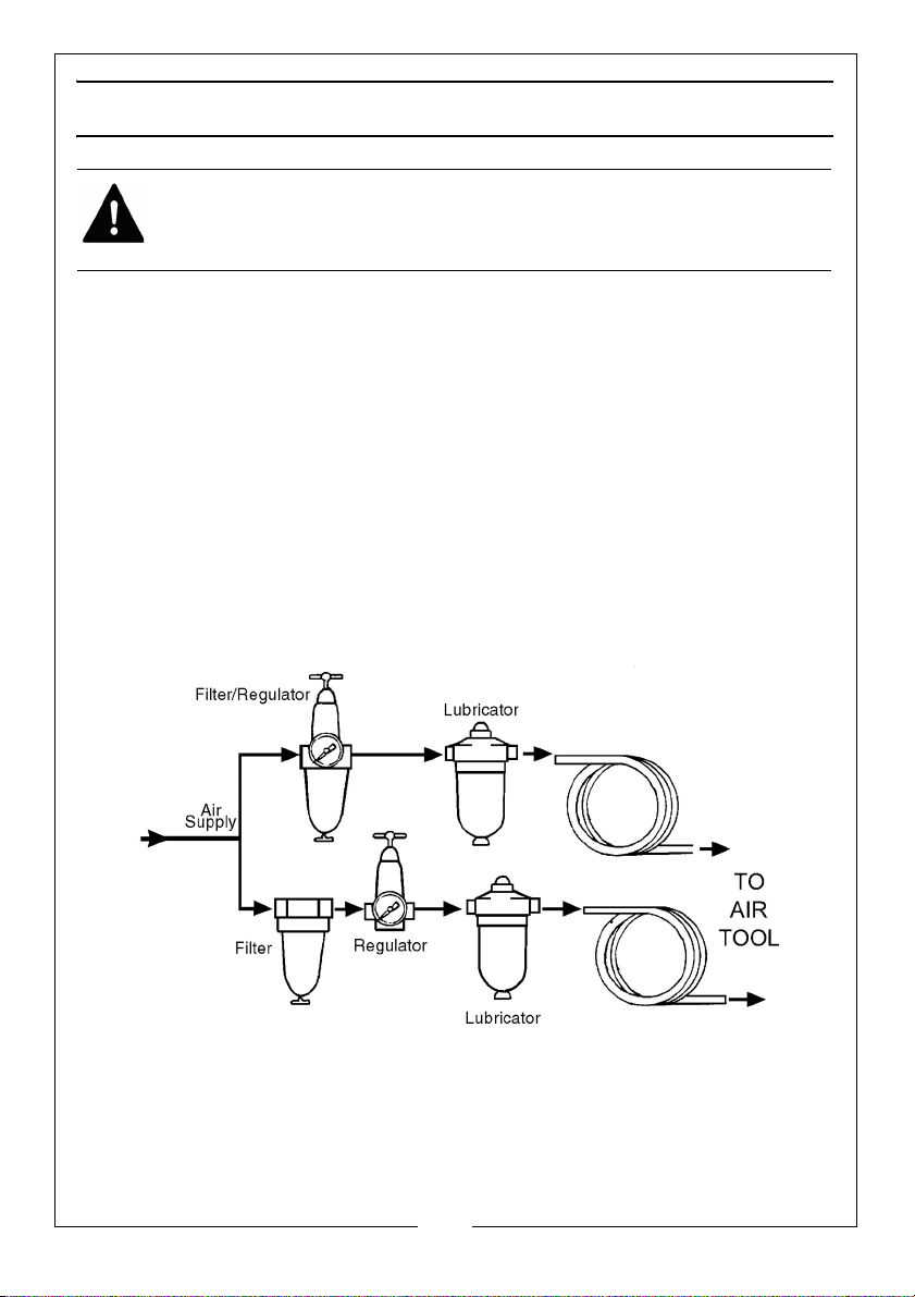
RECOMMENDED AIR SUPPLY CONNECTION
7
Parts & Service: 020 8988 7400 / E-mail: [email protected] or [email protected]
Page 8
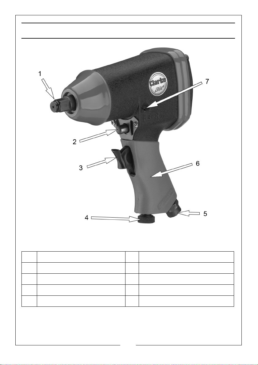
THE IMPACT WRENCH
1
2
3
4
5
6
7
NO DESCRIPTION NO DESCRIPTION
1 1/2” Square Drive Anvil 5 1/4” BSP (Female Air Inlet)
2 Forward / Reverse Button 6 Handle
3 Trigger 7 Oil Port
4 Speed Control
Parts & Service: 020 8988 7400 / E-mail: [email protected] or [email protected]
8
Page 9
BEFORE USE
WARNING: COMPRESSED AIR CAN BE DANGEROUS. ENSURE THAT YOU
ARE FAMILIAR WITH ALL PRECAUTIONS RELATING TO THE USE OF
COMPRESSORS AND COMPRESSED AIR SUPPLY.
NOTE: Ensure the compressor is turned off.
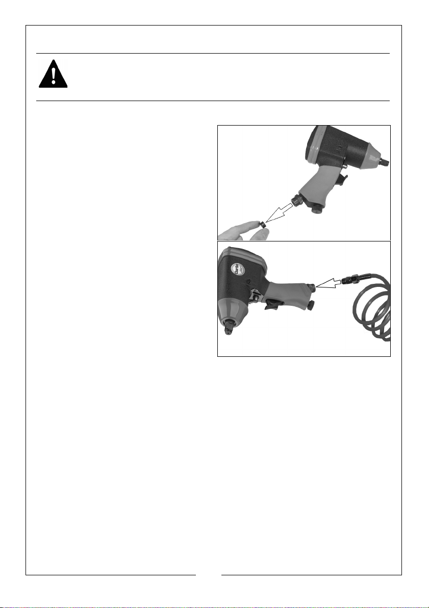
1. Remove the travel plug from the 1/
4” BSP (Female Air Inlet) as shown.
2. Pour 2-3 drops of CLARKE airline oil
into the air inlet. This should be
done regardless of whether or not
a lubricated air supply is to be
used.
3. Connect a suitable hose to the
impact wrench as shown.
• Use the adapter supplied if
required.
4. Connect the other end of the hose
to the compressor.
5. Your impact wrench is now ready
for use.
You can fit a whip hose with a quick fit
coupling if required (available from your Clarke dealer.)
9
Parts & Service: 020 8988 7400 / E-mail: [email protected] or [email protected]
Page 10
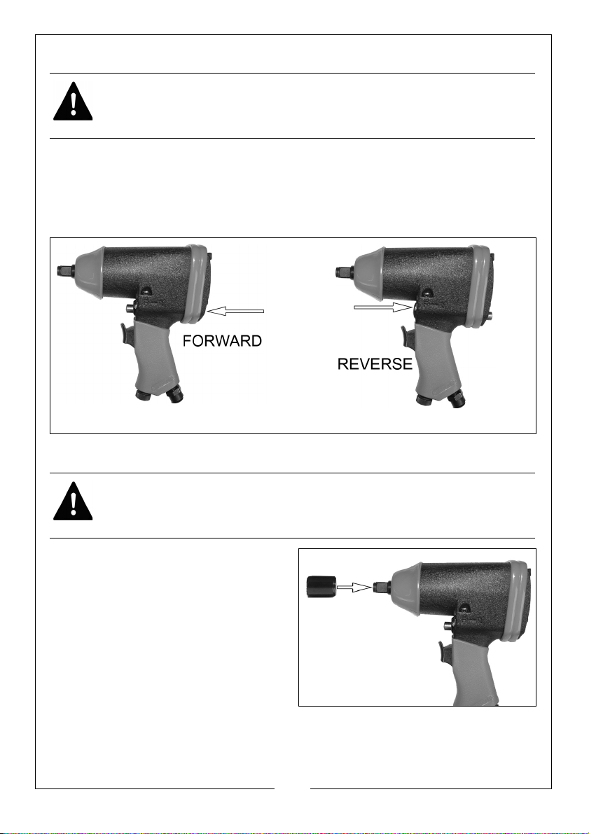
USING THE FORWARD/REVERSE BUTTON
FORWARD
REVERSE
WARNING: WAIT UNTIL THE ANVIL HAS STOPPED ROTATING BEFORE
OPERATING THE FORWARD/REVERSE BUTTON.
The Forward/Reverse button should be used as follows.
1. For normal tightening, the impact wrench should be operated in the
forward (F) direction.
2. For loosening, the impact wrench should be operated in the reverse (R)
direction.
FITTING THE IMPACT SOCKET
WARNING: NEVER USE STANDARD SOCKETS. THESE MAY SHATTER WITH
SERIOUS CONSEQUENCES. ONLY USE ACCESSORIES DESIGNED FOR USE
WITH IMPACT TOOLS.
1. Select the impact socket you
require.
2. Push the impact socket onto the
anvil as shown.
10
Parts & Service: 020 8988 7400 / E-mail: [email protected] or [email protected]
Page 11
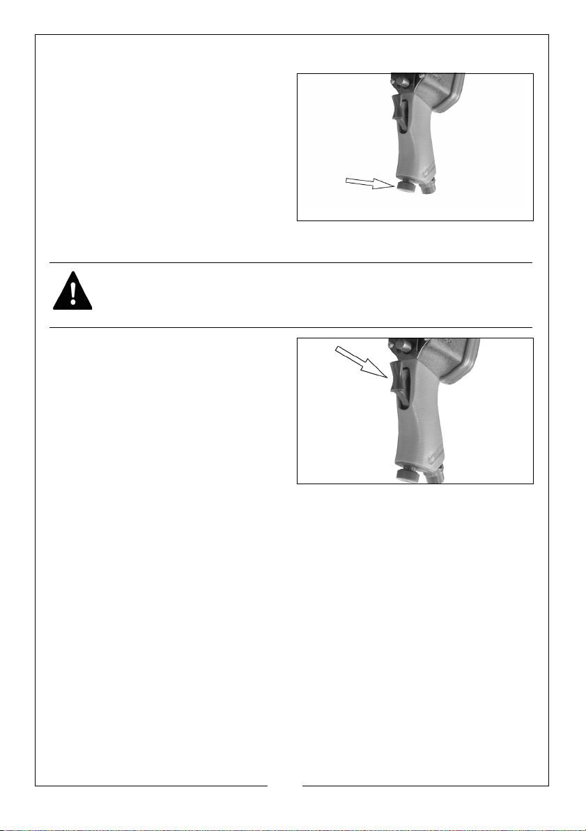
ADJUSTING THE POWER
To adjust the power, set the air regulator
to one of the 4 settings available.
1 (Low) - 4 (High).
OPERATING THE IMPACT WRENCH
WARNING: MAKE SURE THAT THE CHUCK KEY HAS BEEN REMOVED
BEFORE USING THE DRILL.
1. Locate the socket over the nut to
be tightened or loosened.
2. Squeeze the trigger to start the
impact wrench.
3. Release the trigger switch to stop
the Impact Wrench.
• The anvil will continue to rotate
briefly after the trigger has been
released.
DISCONNECTING THE AIR SUPPLY
Do not disconnect the air supply hose until the compressor has been shut
down and the compressed air released.
1. Refer to the compressor instruction book for the procedures to shut down
and release the compressed air.
2. Once the pressure has been released, disconnect the air supply hose from
the Impact Wrench.
3. Store the Impact Wrench safely in its box in a dry, secure environment.
11
Parts & Service: 020 8988 7400 / E-mail: [email protected] or [email protected]
Page 12
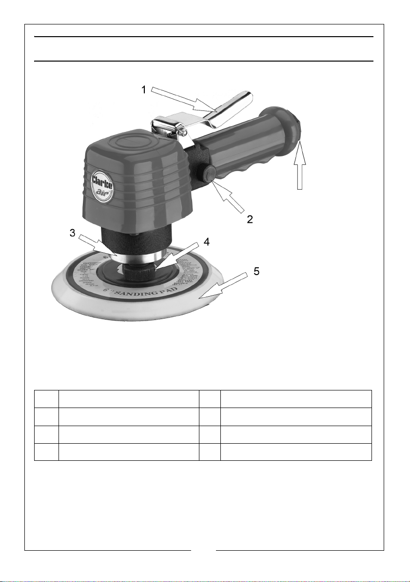
THE DUAL ACTION SANDER
1
2
3
4
5
6
NO DESCRIPTION NO DESCRIPTION
1Trigger 4Locking Nut
2 Speed Control 5 Backing Pad
3 Balancer 6 1/4” BSP (Female Air Inlet)
12
Parts & Service: 020 8988 7400 / E-mail: [email protected] or [email protected]
Page 13
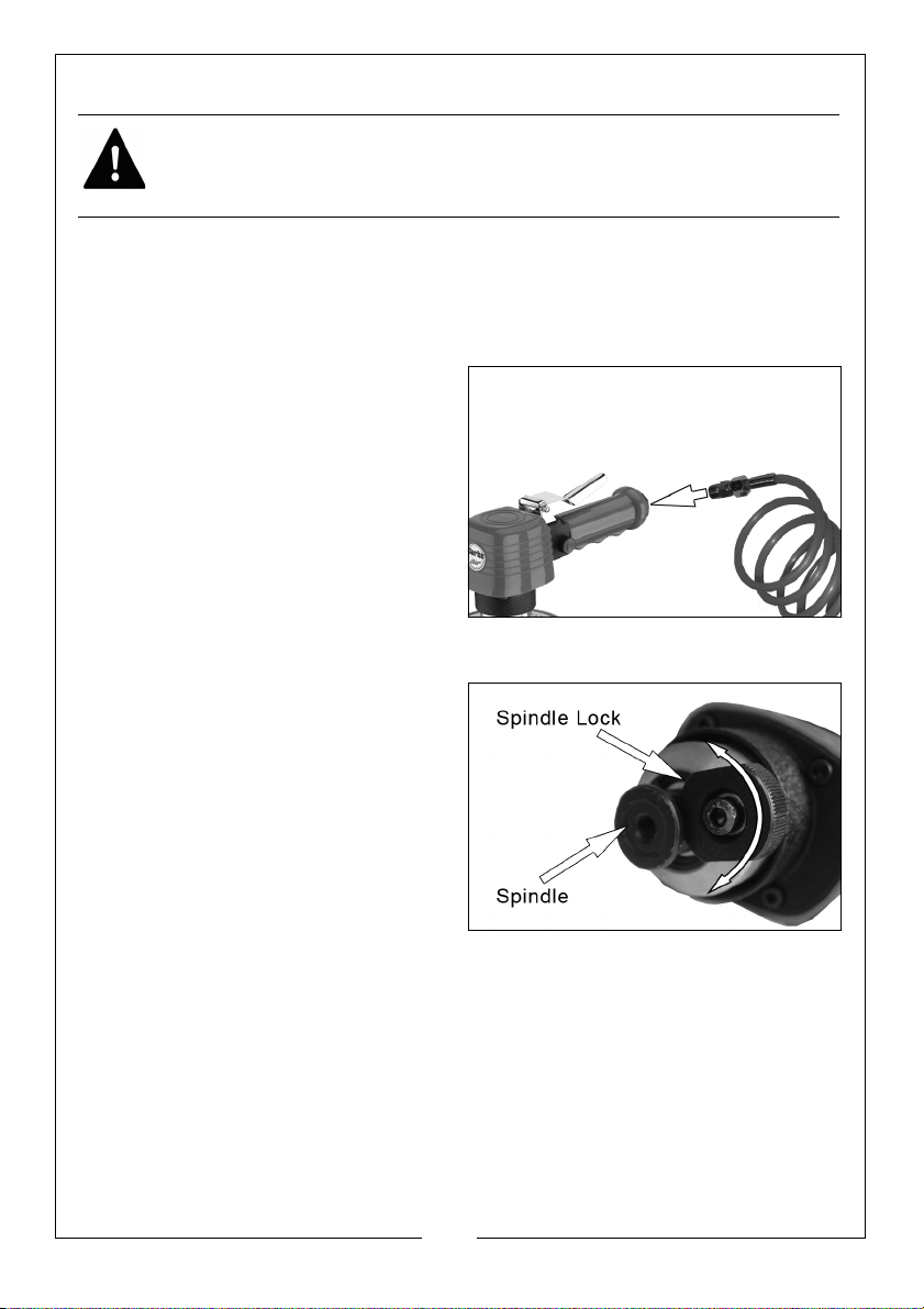
BEFORE USE
WARNING: COMPRESSED AIR CAN BE DANGEROUS. ENSURE THAT YOU
ARE FAMILIAR WITH ALL PRECAUTIONS RELATING TO THE USE OF
COMPRESSORS AND COMPRESSED AIR SUPPLY.
NOTE: Ensure the compressor is turned off.
1. Remove the travel plug from the bottom of the tool.
2. Pour 2-3 drops of CLARKE airline oil into the air inlet. This should be done
regardless of whether or not a lubricated air supply is to be used.
3. Connect a suitable hose to the
tool as shown.
• Use the adapter supplied if
required.
4. Connect the other end of the hose
to the compressor.
You can fit a whip hose with a quick fit
coupling if required (available from
your Clarke dealer.)
FITTING THE BACKING PAD
1. Turn spindle lock until the knurled
portion contacts the flat surface
on the Spindle.
2. Thread the backing pad into the
spindle, by grasping the balancer,
with one hand and the pad with
the other. Do not over tighten.
3. Now turn the spindle lock so that
the knurled portion is away from
the flat on the spindle, and the
spindle turns freely.
4. DO NOT operate tool with spindle in locked mode as performance would
be severely affected, and a hazardous situation may result.
FITTING THE SANDING SHEET
1. Peel off the back of the self adhesive sanding sheet and stick it to the
backing pad.
13
Parts & Service: 020 8988 7400 / E-mail: [email protected] or [email protected]
Page 14
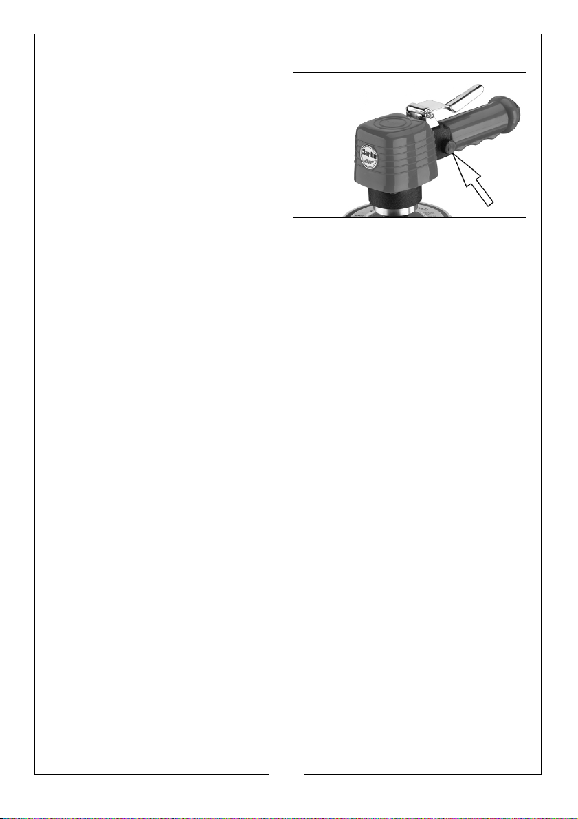
ADJUSTING THE SPEED
Adjust the operating speed if
required, by twisting the speed
control.
• Clockwise to increase the
sanding speed.
• Anticlockwise to decrease the
sanding speed.
USING THE SANDER
1. Place the sander on the workpiece and press down on the trigger to start
the sander.
2. Release pressure from the trigger to stop the sander.
3. Always ensure the sander has stopped before putting it down on any
surface after use.
14
Parts & Service: 020 8988 7400 / E-mail: [email protected] or [email protected]
Page 15
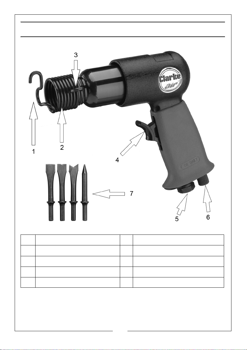
THE CHIPPING HAMMER
1
2
3
4
5
6
7
8
NO DESCRIPTION NO DESCRIPTION
1 Retainer spring 5 Speed controller/air regulator
2 Main body 6 Outboard lug
3 Trigger 7 Inboard lug
4 1/4” BSP (Female Air Inlet) 8 Chisel set
15
Parts & Service: 020 8988 7400 / E-mail: [email protected] or [email protected]
Page 16
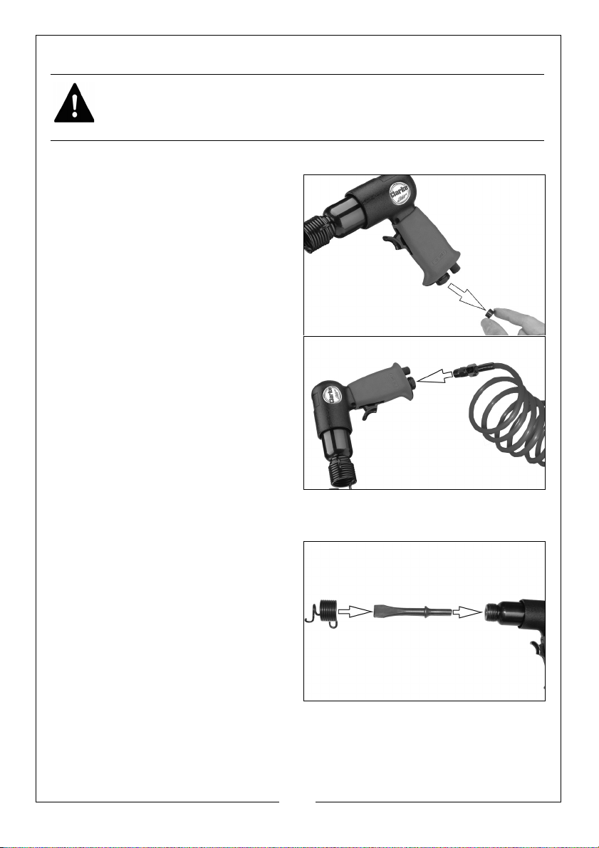
BEFORE USE
WARNING: COMPRESSED AIR CAN BE DANGEROUS. ENSURE THAT YOU
ARE FAMILIAR WITH ALL PRECAUTIONS RELATING TO THE USE OF
COMPRESSORS AND COMPRESSED AIR SUPPLY.
NOTE: Ensure the compressor is turned off.
1. Remove the travel plug from the
bottom of the tool as shown.
2. Pour 2-3 drops of CLARKE airline oil
into the air inlet. This should be
done regardless of whether or not
a lubricated air supply is to be
used.
3. Connect a suitable hose to the
tool as shown.
• Use the adapter supplied if
required.
4. Connect the other end of the hose
to the compressor.
You can fit a whip hose with a quick fit
coupling if required (available from
your Clarke dealer.)
FITTING THE CHISEL
1. First remove the spring from the
nose by unscrewing it.
• Use the inboard lug to gain
purchase.
2. Insert the end of the chisel into the
chipping hammer.
3. Replace the spring, as shown.
• Use the outboard lug to tighten.
16
Parts & Service: 020 8988 7400 / E-mail: [email protected] or [email protected]
Page 17
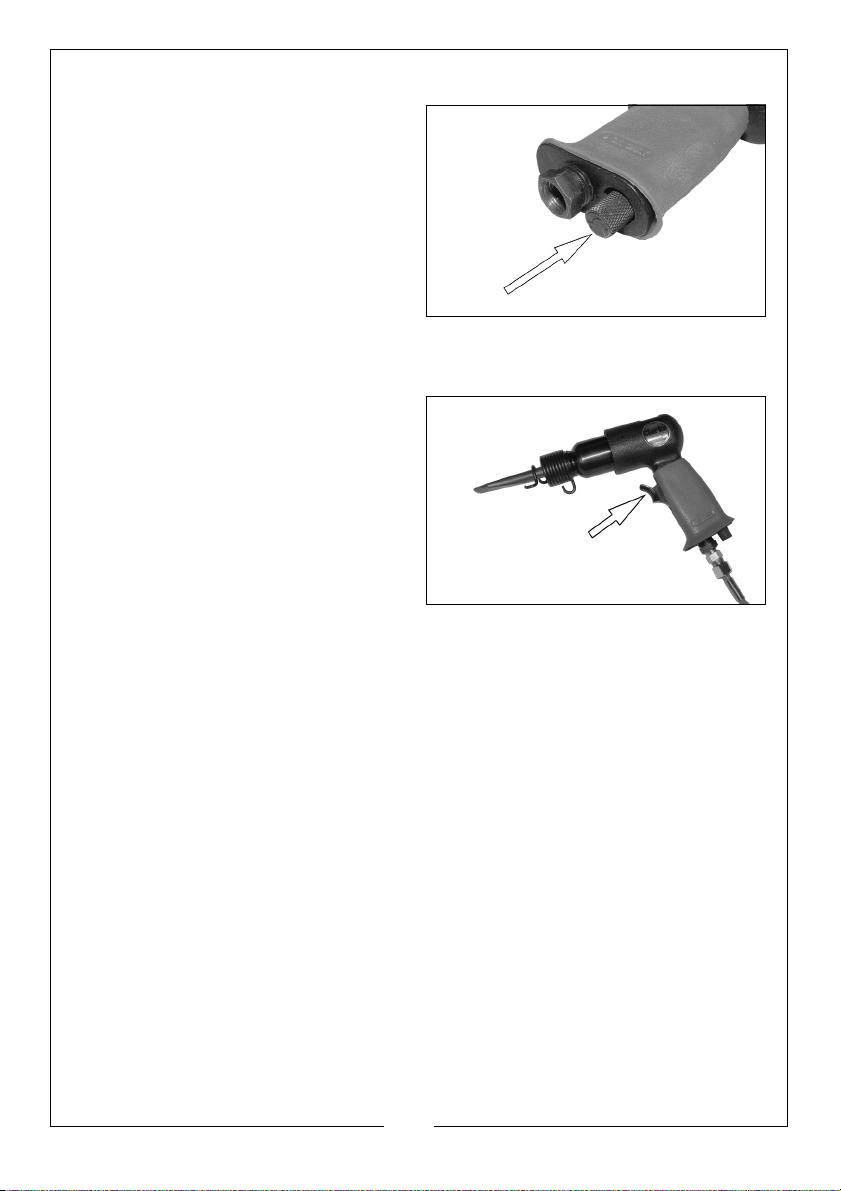
ADJUSTING THE FORCE
Chisel force may be adjusted by
turning the Speed controller/air
regulator located at the base of the
handle grip.
• Turn anticlockwise to increase
force.
• Turn clockwise to reducethe
force.
USING THE CHIPPING HAMMER
1. Hold the tool with one hand
around the handle and one hand
around the barrel, then bring the
tool towards the work at an angle
of approximately 60-70 degrees.
2. Pull the trigger with the chisel in
light contact with the work.
3. Move slowly across the work
surface and proceed to remove
scale, rust or other contaminants, a light force only should be required.
4. Release the trigger to stop operation, whilst maintaining contact with the
work, noting that the tool may impact briefly after the trigger is released.
NOTE: The Retaining Spring has a life expectancy, depending upon the
intensity of usage. It is strongly recommended that you obtain one
or two spare springs, for use in the event of failure occurring
during use. These are available from the Clarke Spares
department.
17
Parts & Service: 020 8988 7400 / E-mail: [email protected] or [email protected]
Page 18
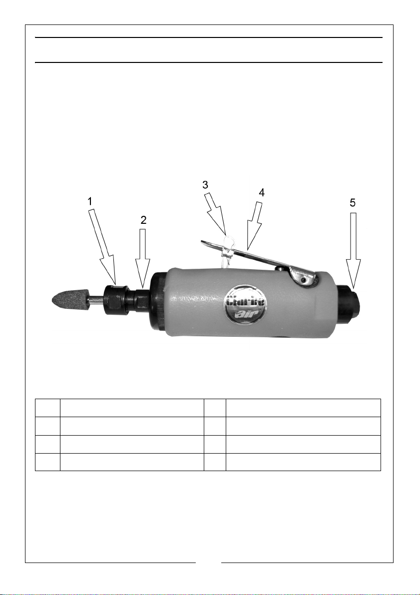
THE DIE GRINDER
1
2
3
4
5
NO DESCRIPTION NO DESCRIPTION
1 Collet nut 4 Trigger
2Spindle 51/4” BSP (Female Air Inlet)
3Trigger Lock
Parts & Service: 020 8988 7400 / E-mail: [email protected] or [email protected]
18
Page 19
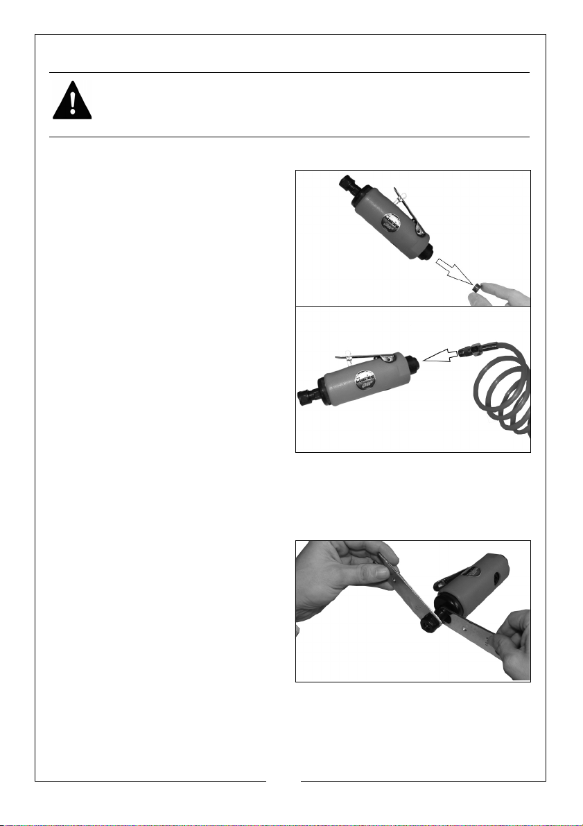
BEFORE USE
WARNING: COMPRESSED AIR CAN BE DANGEROUS. ENSURE THAT YOU
ARE FAMILIAR WITH ALL PRECAUTIONS RELATING TO THE USE OF
COMPRESSORS AND COMPRESSED AIR SUPPLY.
NOTE: Ensure the compressor is turned off.
1. Remove the travel plug from the
bottom of the tool as shown.
2. Pour 2-3 drops of CLARKE airline oil
into the air inlet. This should be
done regardless of whether or not
a lubricated air supply is to be
used.
3. Connect a suitable hose to the
tool as shown.
• Use the adapter supplied if
required.
4. Connect the other end of the hose
to the compressor.
You can fit a whip hose with a quick fit
coupling if required (available from
your Clarke dealer.)
COLLETS
Two collets of different sizes are provided (1/8” and 1/4”). Select whichever fits
the shank of the stone you have chosen to use.
If you need to change the collet,
follow instructions below.
1. Hold motor spindle from turning
with spanners supplied.
19
Parts & Service: 020 8988 7400 / E-mail: [email protected] or [email protected]
Page 20
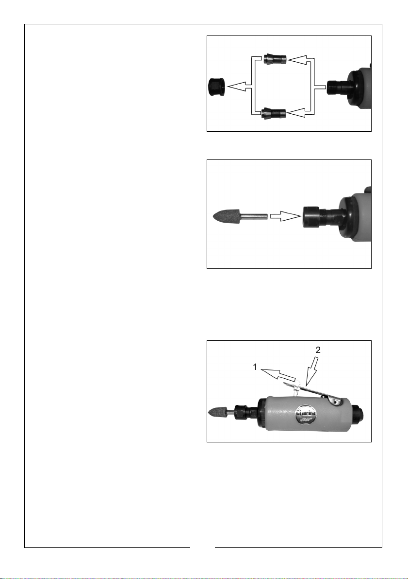
2. Remove collet nut and withdraw
collet.
3. Install new collet and re-fit collet
nut, (finger-tight only).
FITTING THE GRINDING POINT OR STONE
1. Loosen collet nut using the
spanners supplied.
2. Insert appropriate die grinding
point or stone.
IMPORTANT: You MUST have at least
half of the length of the spindle inside
the collet before use.
3. Tighten the collet using spanners
supplied
IMPORTANT: Never use chipped or cracked points or stones, always inspect
before fitting.
USING THE DIE GRINDER
1. Slide and hold the safety lever
forward (1) and depress throttle
lever (2).
• Wait until the die grinder is
running at full speed.
2. Cautiously offer stone to
workpiece.
• DO NOT APPLY EXCESS FORCE,
too much pressure could cause
stone to shatter resulting in personal injury.
3. When finished grinding, allow the tool to stop completely before putting it
down.
20
Parts & Service: 020 8988 7400 / E-mail: [email protected] or [email protected]
Page 21
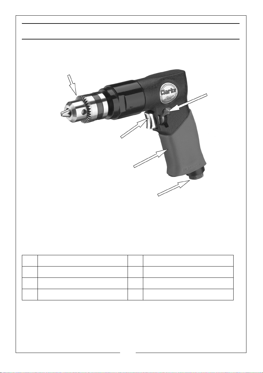
THE REVERSIBLE DRILL
1
2
3
4
5
NO DESCRIPTION NO DESCRIPTION
1Chuck 4Handle
2 Trigger 5 1/4” BSP (Female Air Inlet)
3 Direction control switch
21
Parts & Service: 020 8988 7400 / E-mail: [email protected] or [email protected]
Page 22
BEFORE USE
Drill bit
Chuck jaws
Cog
Close
Open
Chuck
key
jaws
jaws
barrel
WARNING: COMPRESSED AIR CAN BE DANGEROUS. ENSURE THAT YOU
ARE FAMILIAR WITH ALL PRECAUTIONS RELATING TO THE USE OF
COMPRESSORS AND COMPRESSED AIR SUPPLY.
NOTE: Ensure the compressor is turned off.
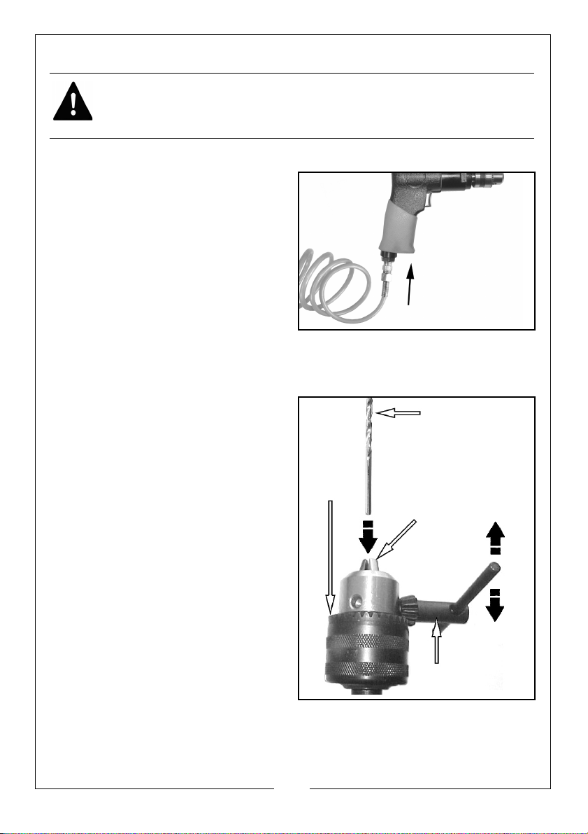
1. Remove the travel plug from the
air hose socket.
2. Connect a suitable hose to the air
drill as shown, use the adapter
supplied if required.
3. Connect the other end of the hose
to the compressor.
4. Your air drill is now ready for use.
You can fit a whip hose with a quick fit
coupling if required (available from your Clarke dealer.)
INSERTING/REMOVING THE DRILL BIT
1. Open the chuck jaws by inserting
the chuck key in one of the holes
in the chuck and turning it as
shown.
• Make sure that the head of the
chuck key is located on the cog
barrel of the chuck.
2. Open sufficiently to take the drill
bit.
3. Place the drill bit in the jaws of the
chuck as far as it will go.
4. Close the chuck jaws and tighten
to grip the drill bit by turning the
chuck key as shown.
5. Make sure that the chuck jaws are
fully closed and that the drill bit is
firmly held.
Parts & Service: 020 8988 7400 / E-mail: [email protected] or [email protected]
22
Page 23
DIRECTION CONTROL SWITCH
WARNING: WAIT UNTIL THE CHUCK HAS STOPPED ROTATING BEFORE
OPERATING THE DIRECTION CONTROL SWITCH.
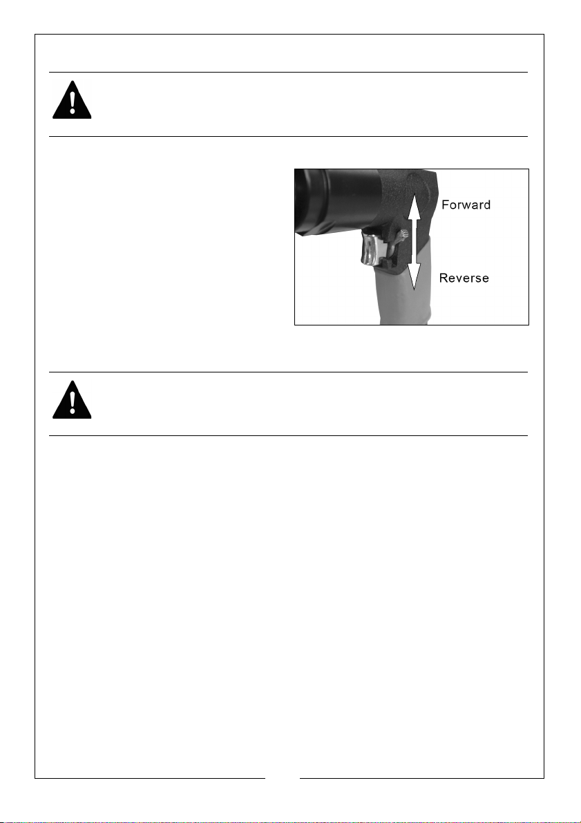
The direction control switch should be used as follows.
1. For normal drilling into wood,
metal and masonry, the drill should
be operated in the forward (F)
direction.
2. If the drill bit jams whilst drilling,
release the trigger switch.
3. When the drill has come to a
complete stop, move the direction
control switch to the reverse (R)
position.
USING THE REVERSIBLE DRILL
WARNING: MAKE SURE THAT THE CHUCK KEY HAS BEEN REMOVED
BEFORE USING THE DRILL.
1. Squeeze the trigger switch to start the air drill.
2. Wait until the air drill is running at its maximum speed before applying it
carefully to the workpiece.
3. Release the trigger switch to stop the air drill.
23
Parts & Service: 020 8988 7400 / E-mail: [email protected] or [email protected]
Page 24

AFTER USE
DISCONNECTING THE AIR SUPPLY
Do not disconnect the air supply hose until the compressor has been shut
down and the compressed air released.
1. Refer to the compressor instruction book for the procedures to shut down
and release the compressed air.
2. Once the pressure has been released, disconnect the air supply hose from
the tool.
3. Store the tool safely in its box in a dry, secure environment.
STORAGE
• If the tool is to be stored, or is idle for longer than 24 hours, run a few
drops of Clarke air line oil into the air inlet, and run the tool for 5
seconds in order to lubricate the internal parts.
• When not in use, disconnect from air supply, clean tool and store in
a safe, dry place.
24
Parts & Service: 020 8988 7400 / E-mail: [email protected] or [email protected]
Page 25

MAINTENANCE
WARNING: MAKE SURE THAT THE TOOL IS DISCONNECTED FROM THE AIR
SUPPLY BEFORE STARTING ANY CLEANING, OR MAINTENANCE
PROCEDURES.
DAILY
• Drain water from air tank, air line and compressor.
• Pour a few drops of CLARKE Air Line Oil, into the air inlet. This should
be carried out regardless of whether or not the inline mini oiler is
used. If the inline mini oiler is not used, this procedure should be
repeated after every two to three hours of use.
NOTE: **Clarke Air Line Oil (part no. 3050825) is available from your
CLARKE dealer.
WEEKLY
• Remove the grub screw from the oil port on the side of the impact
wrench and insert a few drops of oil.
CLEANING
• Keep the body of the tool clean and free from debris, grit or gum
deposits in the tool which may reduce efficiency.
SERVICE AND REPAIR
All servicing and repair must be carried out by qualified service technicians.
NOTE: Please note that factors other than the tool may effect its
operation and efficiency such as reduced compressor output,
excessive drain on the airline, moisture or restrictions in the line, or
the use of connectors of improper size or poor condition which will
reduce air supply.
25
Parts & Service: 020 8988 7400 / E-mail: [email protected] or [email protected]
Page 26

SPECIFICATIONS - GENERAL
Air
Consumption
Operating
Pressure
Air Inlet Size
Sound
Pressure Level
(L
pA dB)
Guaranteed
Sound Power
(L
wA dB)
Vibration
Levels
Dimensions
(L x W x H)
mm
Weight
6 cfm
(170 l/min)
90 psi
(6.2 bar)
1.2 m/s
Main Handle
2
K = 1.25 m/s
Reversible
Drill
2
at
Impact
Wrench
8 cfm
(226 l/min)
90 psi
(6.2 bar)
1/4 inch BSP 1/4 inch BSP 1/4 inch BSP 1/4 inch BSP 1/4 inch BSP
84.4 dB(A) 87.2 dB(A) 84 dB(A) 83.5 dB(A) 87dB(A)
95.4 dB(A) 98.2 dB(A) 95 dB(A) 94.5 dB(A) 98 dB(A)
2.6 m/s2 at
Main Handle
K = 0.72 m/s
220 x 75 x 180 223 x 73 x 123 153 x 48 x 152 173 x 100 x 46 200 x 42 x 144
2.2 kg 1.81 Kg 1.09 Kg 0.64 kg 1.15 kg
Dual Action
Sander
2-16 cfm
(56 - 452 l/min)
90 psi
(6.2 bar)
2.5 m/s
Main Handle
2
K = 1.25 m/s
2
at the
3 - 16 cfm
(84 - 452 l/min)
90 psi
(6.2 bar)
14.6 m/s
Main Handle
2
K = 0.99 m/s
Chipping
Hammer
2
at the
2
Die Grinder
14 cfm
(396 l/min)
90 psi
(6.2 bar)
2
1.2 m/s
at
Main Handle
K = 0.35 m/s
2
26
Parts & Service: 020 8988 7400 / E-mail: [email protected] or [email protected]
Page 27
SPECIFICATIONS - MODEL SPECIFIC
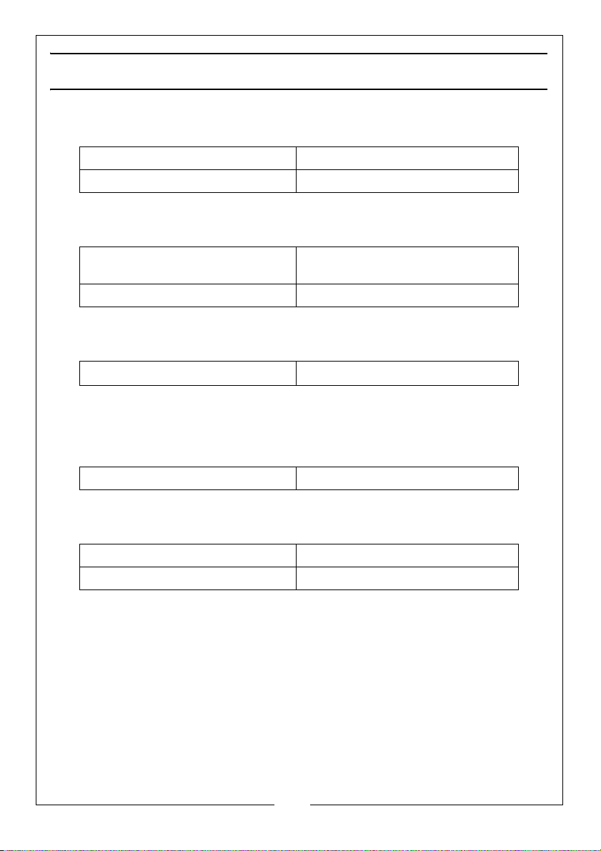
IMPACT WRENCH
No Load Speed 7000 rpm
Maximum Torque 230 ft/lb
DUAL ACTION SANDER
Pad Size 143 mm To be fitted with 150mm
Maximum Speed 10000 rpm
sanding disc'
CHIPPING HAMMER
Maximum Speed
4500 Blows per Min.
DIE GRINDER
Maximum Speed 22000 rpm
AIR DRILL
Chuck Size 1.5 - 10 mm
Maximum Speed 1770 rpm
Please note that the details and specifications contained herein, are correct at
the time of going to print. However CLARKE International reserve the right to
change specifications at any time without prior notice. Always consult the
machine’s data plate
27
Parts & Service: 020 8988 7400 / E-mail: [email protected] or [email protected]
Page 28
VIBRATION EMISSIONS
Employers are advised to refer to the HSE publication “Guide for Employers”.
All hand held power tools vibrate to some extent, and this vibration is
transmitted to the operator via the handle, or hand used to steady the tool.
Vibration from about 2 to 1500 hertz is potentially damaging and is most
hazardous in the range from about 5 to 20 hertz.
Operators who are regularly exposed to vibration may suffer from Hand Arm
Vibration Syndrome (HAVS), which includes ‘dead hand’, ‘dead finger’, and
‘white finger’. These are painful conditions and are widespread in industries
where vibrating tools are used.
The health risk depends upon the vibration level and the length of time of
exposure to it……in effect, a daily vibration dose.
Tools are tested using specialised equipment, to approximate the vibration
level generated under normal, acceptable operating conditions for the tool in
question. For example, a grinder used at 45° on mild steel plate, or a sander on
soft wood in a horizontal plane etc.
These tests produce a value ‘a’, expressed in metres per second per second,
which represents the average vibration level of all tests taken, in three axes
where necessary, and a second figure ‘K’, which represents the uncertainty
factor, i.e. a value in excess of ‘a’, to which the tool could vibrate under
normal conditions. These values appear in “Specifications - General” on
page 26.
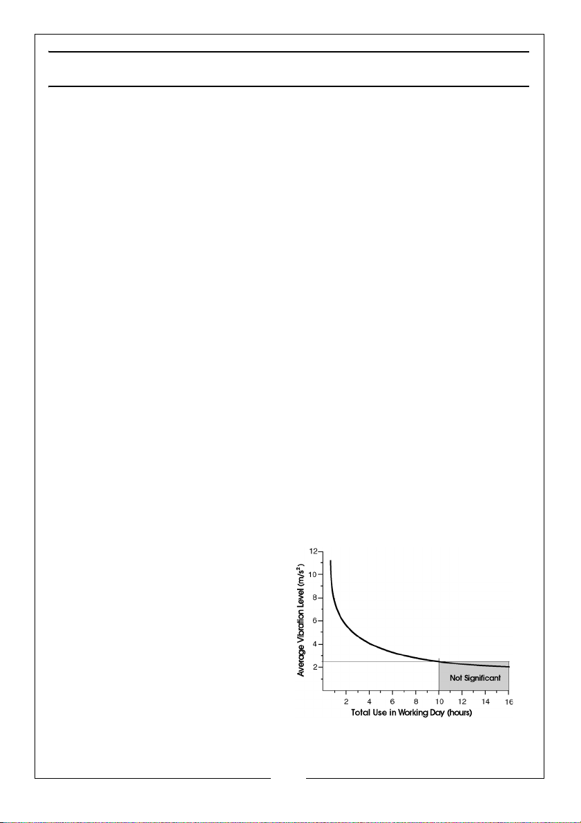
‘a’ values in excess of 2.5 m/s
prolonged periods. A tool with a vibration value of 2.8 m/s
to 8 hours (cumulative) per day, whereas a tool with a value of 11.2 m/s
be used for ½ hour per day only.
The graph on the right shows the
vibration value against the maximum
time the respective tool may be
used, per day.
The uncertainty factor should also be
taken into account when assessing a
risk. The two figures ‘a’ and ‘K’ may
be added together and the resultant
value used to assess the risk.
It should be noted that if a tool is
used under abnormal, or unusual
conditions, then the vibration level
2
are considered hazardous when used for
2
may be used for up
2
may
28
Parts & Service: 020 8988 7400 / E-mail: [email protected] or [email protected]
Page 29

could possibly increase significantly. Users must always take this into account
and make their own risk assessment, using the graph above as a reference.
Some tools with a high vibration value, such as impact wrenches, are
generally used for a few seconds at a time, therefore the cumulative time
may only be in the order of a few minutes per day. Nevertheless, the
cumulative effect, particularly when added to that of other hand held power
tools that may be used, must always be taken into account when the total
daily dose rate is determined.
29
Parts & Service: 020 8988 7400 / E-mail: [email protected] or [email protected]
Page 30
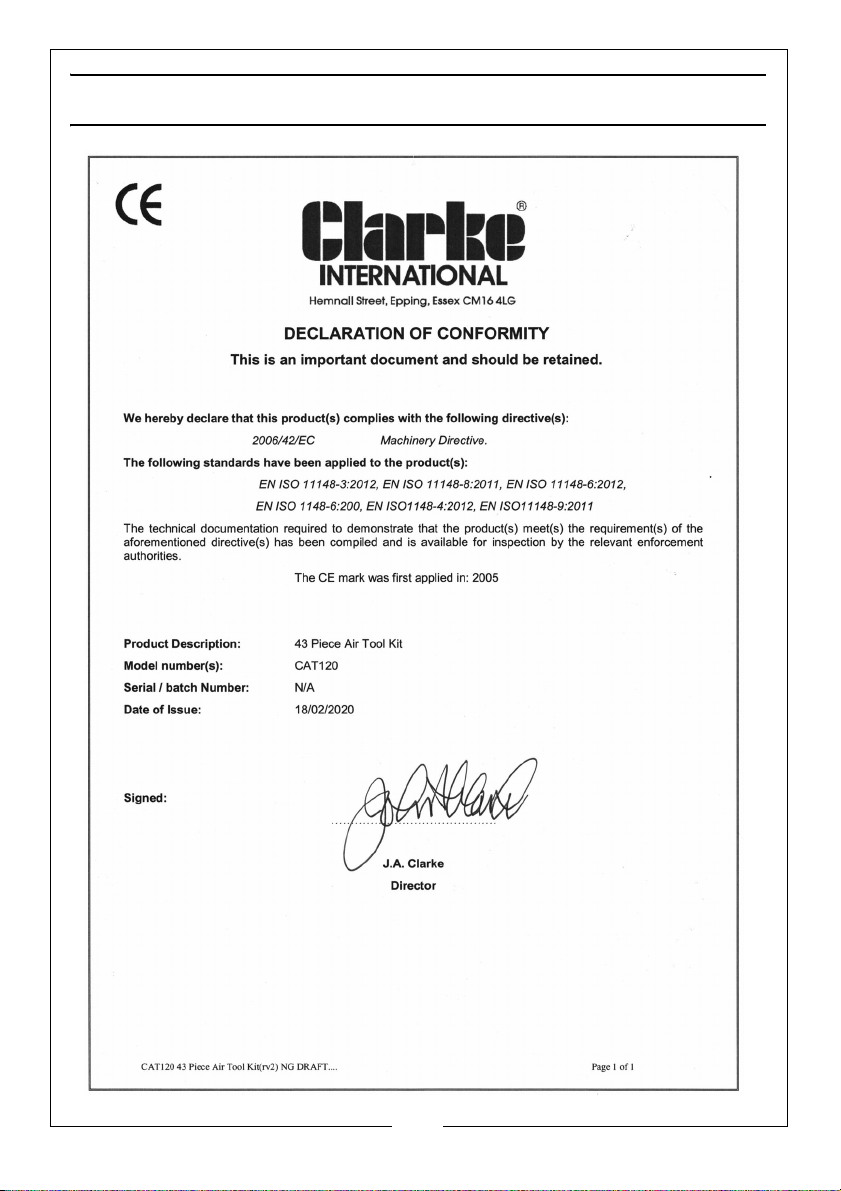
DECLARATION OF CONFORMITY
30
Parts & Service: 020 8988 7400 / E-mail: [email protected] or [email protected]
Page 31

Page 32

 Loading...