

Page 1

14 PIECE DIE GRINDER KIT
MODEL No: CAT112
Part No: 3120132
OPERATING & MAINTENANCE
INSTRUCTIONS
GC0409
Page 2

INTRODUCTION
Thank you for purchasing this CLARKE product.
Before attempting to use the tool, please read this manual thoroughly and
follow the instructions carefully. In doing so you will ensure the safety of
yourself and that of others around you, and you can look forward to the tool
giving you long and satisfactory service.
GUARANTEE
This CLARKE product is guaranteed against faulty manufacture for a period of
12 months from the date of purchase. Please keep your receipt as proof of
purchase.
This guarantee is invalid if the product is found to have been abused or
tampered with in any way, or not used for the purpose for which it was
intended.
Faulty goods should be returned to their place of purchase, no product can
be returned to us without prior permission.
This guarantee does not effect your statutory rights.
ENVIRONMENTAL PROTECTION
Do not dispose of this product with general household waste. All tools,
accessories and packaging should be sorted, taken to a recycling
centre and disposed of appropriately.
PARTS & SERVICING
For parts & Servicing, please contact your nearest dealer, or
CLARKE International, on one of the following numbers.
PARTS & SERVICE TEL: 020 8988 7400
PARTS & SERVICE FAX: 020 8558 3622
or e-mail as follows:
PARTS: Parts@clarkeinternational.com
SERVICE: Service@clarkeinternational.com
2
Page 3

CONTENTS
Introduction ............................................................................................ 2
Guarantee .............................................................................................. 2
Environmental Protection ...................................................................... 2
Parts & Service Contacts ....................................................................... 2
Table of Contents ................................................................................... 3
Technical Specification......................................................................... 3
Overview ................................................................................................ 4
General Safety Precautions .................................................................. 5
Air Supply Requirements ....................................................................... 7
Assembly & Operation .......................................................................... 8
Troubleshooting.................................................................................... 10
Maintenance ........................................................................................ 11
Parts Lists and Diagrams ..................................................................... 12
Vibration Emissions .............................................................................. 13
Declaration of Conformity .................................................................. 15
TECHNICAL SPECIFICATION
erutaeF noitacificepS
thgieWgk1.1
)hxwxl(snoisnemiDmm86x64x371
MPRxaM000,22
erusserPriAgnikroW)rab2.6(isp09
CriApmoC)nim/l1511(mfc4
Please note that the details and specifications contained herein, are correct at the
time of going to print. However, CLARKE International reserve the right to change
specifications at any time without prior notice.
noitpmusno
deriuqeRnoitcennoCPSB"4/1
levelerusserpdnuosdethgiew/A)A(Bd8.28
levelrewopdnuoS)A(Bd
eldnahehttanoitarbiVs/m9.0
3
8.39
2
Page 4

OVERVIEW
The CAT112 Die Grinder is ideal for light tasks such as automotive porting &
polishing applications. The lightweight composite housing also helps to
reduce vibration & a lever lock throttle is provided for extra safety.
Unpack and lay out the components, checking against the following list. Any
damage or deficiency should be reported to your CLARKE dealer
immediately.
1. Die Grinder
2. Moulded Storage Case
3. Male Snap Connector
4. 2 x Collets
5. 2 x Collet Wrenches
6. 10 Grinding Stones
7. Operators Manual (this document)
Your Die Grinder has been designed to give long and trouble free service. If,
however, having followed the instructions in this booklet carefully, you
encounter problems, take the unit to your local CLARKE dealer.
1 2 3 6 4 5
4
Page 5

GENERAL SAFETY PRECAUTIONS
WORK ENVIRONMENT
• Keep the work area clean and tidy.
• Dress appropriately - Do not wear loose clothing or jewellery. Tie long hair
out of the way.
• Keep children and visitors away - Do not let children handle the die
grinder. Make sure that any other persons in the work area are dressed
suitably and are wearing eye and ear protectors.
• Do not operate the die grinder where there are flammable liquids or
gases.
• Keep the air supply hose away from heat, oil and sharp edges.
• Do not fit the die grinder to any stand or clamping device that may
damage the tool.
GENERAL USE
• Stay alert and use common sense - do not operate the die grinder when
you are tired or under the influence of alcohol, drugs or medication.
• Always wear eye protection when using the die grinder - eye protection
must provide protection from flying particles from the front and the side.
• When grinding, always wear an appropriate face mask or respiratory
equipment to prevent inhalation of airborne dust.
• Always wear ear protectors when using the die grinder.
• Do not over-reach - Keep proper footing and balance at all times.
• Never use any type of bottled gas as a source of power for the die
grinder.
• Do not connect the air supply hose with your finger on the trigger of the
die grinder.
• Do not exceed the maximum pressure for the die grinder: 90 psi / 6.2 bar.
• Check hoses for leaks or worn condition before use and ensure that all
connections are secure.
• Do not use the die grinder for any other purpose than that described in
this booklet.
• Do not carry out any alterations or modifications to the die grinder.
• The die grinder should be serviced as required by your CLARKE dealer.
• Never use the grinder if it is defective or operating abnormally.
5
Page 6

• Always disconnect from the air supply when:
a) Performing any maintenance.
b) The grinder is not in use.
c) The grinder will be left unattended.
d) Moving to another work area.
• Avoid damaging the die grinder for example by applying excessive force.
• ALWAYS maintain the tool with care. Keep it clean for best and safest
performance.
• Quick change air-line couplings should not be located at the tool. They
add weight and could fail due to vibration.
• DO NOT force or misuse the tool. It will do a better and safer job at the
rate for which it was designed.
• This tool vibrates during use. Vibration may be harmful to your hands or
arms. Stop using the tool if discomfort, a tingling feeling or pain occurs and
seek medical advice before resuming use.
• ALWAYS use only the grinding tools supplied with the machine. Nonstandard attachments could become detached during use with serious
consequences.
• ALWAYS ensure that any attachments are correctly fastened before
connecting the tool to the power supply.
• ALWAYS ensure the workpiece is firmly secured leaving both hands free to
control the tool.
• ALWAYS ensure the tool has stopped before putting it down after use.
TRANSPORTATION
• Never carry the die grinder by the air supply hose.
• Never carry the die grinder with your finger on the trigger.
STORAGE
• When not in use the die grinder must be disconnected from the air supply
and stored in a dry place out of the reach of children (preferably in a
locked cabinet).
• Avoid storing the die grinder in environments where the temperature is
below 0
o
C.
6
Page 7

AIR SUPPLY REQUIREMENTS
WARNING: COMPRESSED AIR CAN BE DANGEROUS. ENSURE THAT YOU
ARE THOROUGHLY FAMILIAR WITH ALL PRECAUTIONS RELATING TO THE
USE OF COMPRESSORS AND COMPRESSED AIR SUPPLY.
• Air compressors used with the grinder must comply with the appropriate
European Community safety directives.
• Use only clean, dry, regulated compressed air.
• A build up of moisture in the air compressor will accelerate wear and
corrosion in the grinder. Ensure any moisture is drained from the
compressor daily and the inlet filter is kept clean.
• If an unusually long air hose is required,(over 8 metres), line pressure may
need to be increased.
A typical airline
arrangement is shown
on the right. If an
automatic in-line filter/
regulator/lubricator
unit is used it will keep
the tool in good
condition but should
be regularly checked
and topped up with oil.
IMPORTANT: If a filter/lubricator unit is not used, the grinder should be
lubricated with 2 to 6 drops of oil, at least once a day or after 2 hours work,
depending upon the working environment. The oil can be inserted through
the airline connection point.
AIRLINE SAFETY
• Never exceed the maximum operating pressure for the grinder. A pressure
of 90psi with a flow of 4 cfm is required. Too high an air pressure will shorten
the life of the tool due to excessive wear.
• The air hose must be rated at least 150% of the maximum operating
pressure of the tool.
• Ensure the trigger is OFF before connection the tool to the air supply.
7
Page 8

ASSEMBLY & OPERATION
CONNECTION TO THE AIRLINE
1. Remove the plastic blanking plug
from the connection port of the die
grinder as in Fig 1.
2. Pour 2-3 drops of CLARKE airline oil
into the air inlet. This should be done
regardless of whether or not a
lubricated air supply is to be used.
NOTE: Ensure the airline is turned OFF.
3. Connect a suitable hose to the die
grinder as shown. Use the screw-in
adapter supplied if required.
4. Connect the other end of the hose to
the compressor.
(A whip hose with a quick fit coupling is available from your CLARKE dealer).
5. Turn on the air supply and check for air leaks. Rectify any found before
proceding.
Your die grinder is now ready for use.
INSTALLING THE COLLET
FIG 1
1 Select the grinding stone you
require.
Two collets of different sizes are
provided. Select whichever fits
the shank of the stone you have
chosen. (The larger collet is
probably already installed in the
grinder)
2. If the other collet is to be used,
undo the screw cap completely
and pull out the collet from the
collet seat. Replace it with the
new collet and screw the cap
loosely back on as in Fig 2.
FIG 2
8
Page 9

FITTING THE GRINDING STONE
IMPORTANT: Never use chipped or
cracked grind stones.
1. Slip the shank of the chosen
stone into the collet and
tighten the screw cap finger
tight.
2. Place the smaller of the two
wrenches over the collet seat
to stop the grinder from
rotating.
3. Use the larger wrench to fully
tighten the collet and grip the
stone in position as in Fig 3.
ADJUSTING THE SPEED
1. Regulate the flow of air as
required by adjusting the air
regulator on the body of the
die grinder.
2. To adjust the speed, turn the
air regulator as required using
a screwdriver as in Fig 4.
FIG 3
Air Regulator
OPERATING THE DIE GRINDER
1. Use your thumb to slide the
throttle lock forward at the
same time as squeezing the
trigger against the body of the
tool.
2. Do not use excess pressure on
the grinding stone as this will
shorten its life.
3. Release the trigger to stop the
grinder.
4. Always ensure the grinder has
stopped before putting it down.
FIG 4
FIG 5
9
Page 10

DISCONNECTING THE AIR SUPPLY
1. Do not disconnect the air supply hose until the compressor has been shut
down and the compressed air released from the air line.
2. Once the pressure has been released, disconnect the air line from the die
grinder.
STORAGE
1. Store the die grinder safely in its box in a dry, secure environment.
2. If the grinder is not to be used for longer than 24 hours, run a few drops of
CLARKE airline oil into the air inlet and run the tool for a few seconds to
ensure that the oil has been well distributed throughout the die grinder.
3. When storing, ensure the blanking plug is replaced on the airline
connector once the airline is disconnected.
TROUBLESHOOTING
MOTMYS MELBORP NOITULOS
snurlooTlamronta
rednudaol.
.tsuahxe
.tsuahxe
In the event that any of the above situations occurs that requires dismantling
and overhaul of the tool, contact your CLARKE International Service
Department on 020-8988-7400.
rfylthgilswolf
swolstubdeeps
mo
morfyleerfswolf
riA.ylwolssnurlooT
riA.nurtonlliwlooT
.ffotuhstonlliwlooTsgnir-Oeltt
.noitisop
.laretam
orhT.1
.taesni
.nrowstraprotoM.1
gnikcitsronroW.2
.tnacirbulfo
wolfrialareneG.3
.
tridybdekcolb
10
kcaloteudmsinahcem
demmajstraprotoM.1
.tridro/&mughtiw
desolcnirotalugeR.2
.3
.stsrub
eudkcutssenavrotoM.1
ngieroffopudliubot
.stsrub
.3yltneggnisuohrotompaT
degdolsidrodegamad
.strapgnivom
.ssenilnaelc
.noitisop
trohsnilootetarepO
usriatcennocsiD.1
.yllaunam
ylbmessalootetator
.te
llamrebburhtiw
.strapgnivom
gnir-OecalpeR.1
ri
aperrofrelaedotnruteR.1
liognitacirbullootriapirD.2
kaosdnatelniriaotni
rofretlifriatelnienimaxE.1
nepootrotalugertsujdA.2
&ylpp
trohsnilootgnitarepoyrT.2
liognitacirbullootriapirD.4
kaosdnatelniriaotni
Page 11

MAINTENANCE
WARNING! Make sure that the die grinder is disconnected from the air supply
before starting any cleaning or maintenance procedures.
DAILY
• Drain water from the compressor air
tank and air-line.
• Pour a few drops of CLARKE air line
oil, into the air inlet. This should be
carried out regardless of whether or
not an air line lubricator is used. If an
air-line lubricator is not used, this
procedure should be repeated after
every two to three hours of use.
WEEKLY
• Check the air inlet screen filter and
clean if necessary.
Air Inlet Screen
Filter (located
here)
CLEANING
• Keep the body of the die grinder clean and free from debris, Grit or gum
deposits in the tool may reduce efficiency.
• After extensive use, remove the screen filter and flush out the grinder with
gum solvent oil or an equal mixture of SAE No10 oil and paraffin. Allow to
dry before use.
SERVICE AND REPAIR
• Major servicing and repair must be carried out by your local CLARKE
dealer.
AIRLINE PERFORMANCE
Please note that factors other than the tool may effect its operation and
efficiency such as reduced compressor output, excessive drain on the airline,
moisture or restrictions in the line, or the use of connectors of improper size or
poor condition which will reduce air supply.
**Clarke Air Line Oil is available from your CLARKE dealer part no. 3050825.
ACCESSORIES
A wide range of accessories are available including filter/regulators,
lubricators, high pressure hoses, etc. Contact your CLARKE dealer for further
information, or call CLARKE International on 01992 565333.
11
Page 12

PARTS LIST AND DIAGRAM
oN noitpircseD oNtraP oN noitpircseD oNtraP
1gnisuoH10211TACNOR02niP02211TACNOR
2taeSmetSevlaV20211TACNOR
3reggirT30211TACNOR22edalBrotoR2221
4reggirTelttorhT40211TACNOR32rednilyC32211TACNOR
5gnirpS50211TACNOR42rehsaW42211TACNOR
6niPegniH60211TACNOR52g
7niPegniH70211TACNOR62etalPtnorF62211TACNOR
8gniR-O80211TACNOR72niP72211TACNOR
9gniR-O90211TACNOR82gn
01metSevlaV01211TACNOR92taeStelloC92211TACNOR
11gnirpS11211TACNOR03gniRkcoL03211TACNOR
21rotalugeRr
iA21211TACNOR13paCtnorF13211TACNOR
31gniR-O31211TACNOR23)llams(telloC23211TACNOR
41gniR-O41211TACNOR)egral(telloC332
51paCwercS51211TACNOR33paCwercStelloC43211TACNOR
61revoCelffuM61211TACNOR43)llams(hcnerW53211TACNOR
71gulP
81gniraeB81211TACNOR53rotcennoCelaM73211TACNOR
91etalPdnE91211TACNOR63)
telnIriA71211TACNOR)egral(hcnerW63211TACNOR
12
rotoR
nihsuB52211TACNOR
iraeB82211TACNOR
1TACNOR
11TACNOR
01fotes(srednirG83211TACNOR
12211TACNOR
12
Page 13

VIBRATION EMISSIONS
HAND-ARM VIBRATION
Employers are advised to refer to the HSE publication “Guide for Employers”.
All hand held power tools vibrate to some extent, and this vibration is
transmitted to the operator via the handle, or hand used to steady the tool.
Vibration from about 2 to 1500 herz is potentially damaging and is most
hazardous in the range from about 5 to 20 herz.
Operators who are regularly exposed to vibration may suffer from Hand Arm
Vibration Syndrome (HAVS), which includes ‘dead hand’, ‘dead finger’, and
‘white finger’. These are painful conditions and are widespread in industries
where vibrating tools are used.
The health risk depends upon the vibration level and the length of time of
exposure to it……in effect, a daily vibration dose.
Tools are tested using specialised equipment, to approximate the vibration
level generated under normal, acceptable operating conditions for the tool
in question. For example, a grinder used at 45° on mild steel plate, or a
sander on softwood in a horizontal plane etc.
’
These tests produce a value ‘a
which represents the average vibration level of all tests taken, in three axes
where necessary, and a second figure ‘K’, which represents the uncertainty
factor, i.e. a value in excess of ‘a’, to which the tool could vibrate under
normal conditions. These values appear in the specification panel below.
, expressed in metres per second per second,
MODEL No: CAT112
DESCRIPTION: DIE GRINDER
Declared vibration emission value in accordance
with EN12096
Measured vibration emission value -
2.5m/s
2
a:
less than
Values determined according to EN28662-1
13
Page 14
You will note that a third value is given in the specification - the highest
measured reading in a single plane. This is the maximum level of vibration
measured during testing in one of the axes, and this should also be taken into
account when making a risk assessment.
a
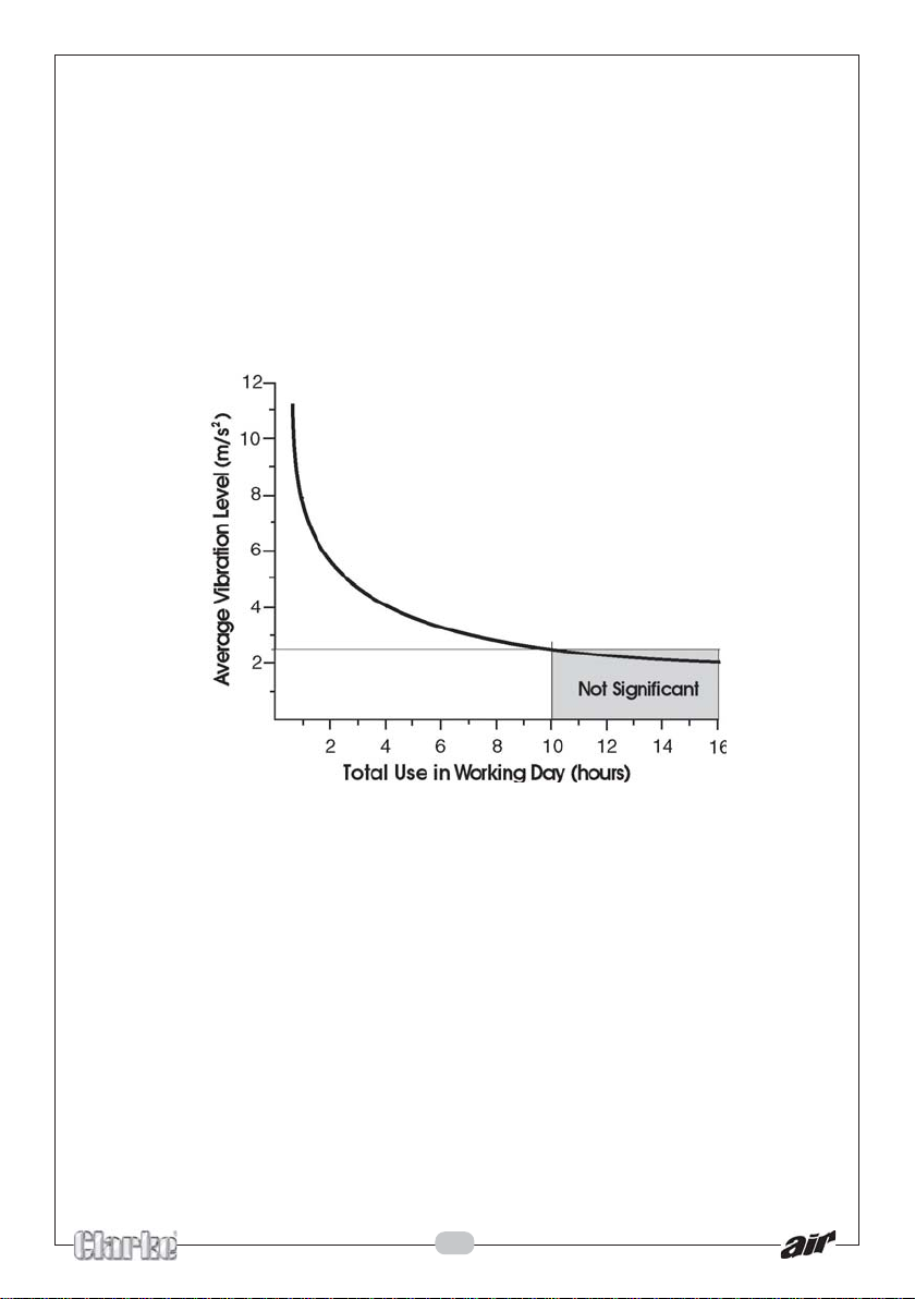
’ values in excess of 2.5 m/s2 are considered hazardous when used for
‘
prolonged periods. A tool with a vibration value of 2.8 m/s2 may be used for
up to 8 hours (cumulative) per day, whereas a tool with a value of 11.2 m/s
2
may be used for ½ hour per day only.
The graph below shows the vibration value against the maximum time the
respective tool may be used, per day.
The uncertainty factor should also be taken into account when assessing a
risk. The two figures ‘a’ and ‘K’may be added together and the resultant
value used to assess the risk.
It should be noted that if a tool is used under abnormal, or unusual conditions,
then the vibration level could possibly increase significantly. Users must always
take this into account and make their own risk assessment, using the graph
above as a reference.
Some tools with a high vibration value, such as impact wrenches, are
generally used for a few seconds at a time, therefore the cumulative time
may only be in the order of a few minutes per day. Nevertheless, the
cumulative effect, particularly when added to that of other hand held power
tools that may be used, must always be taken into account when the total
daily dose rate is determined.
14
Page 15

DECLARATION OF CONFORMITY
15
Page 16

 Loading...