

Page 1

HOSE REEL
MODEL No: CAR8M
Part No: 3120265
INSTRUCTIONS FOR USE
0405
Page 2

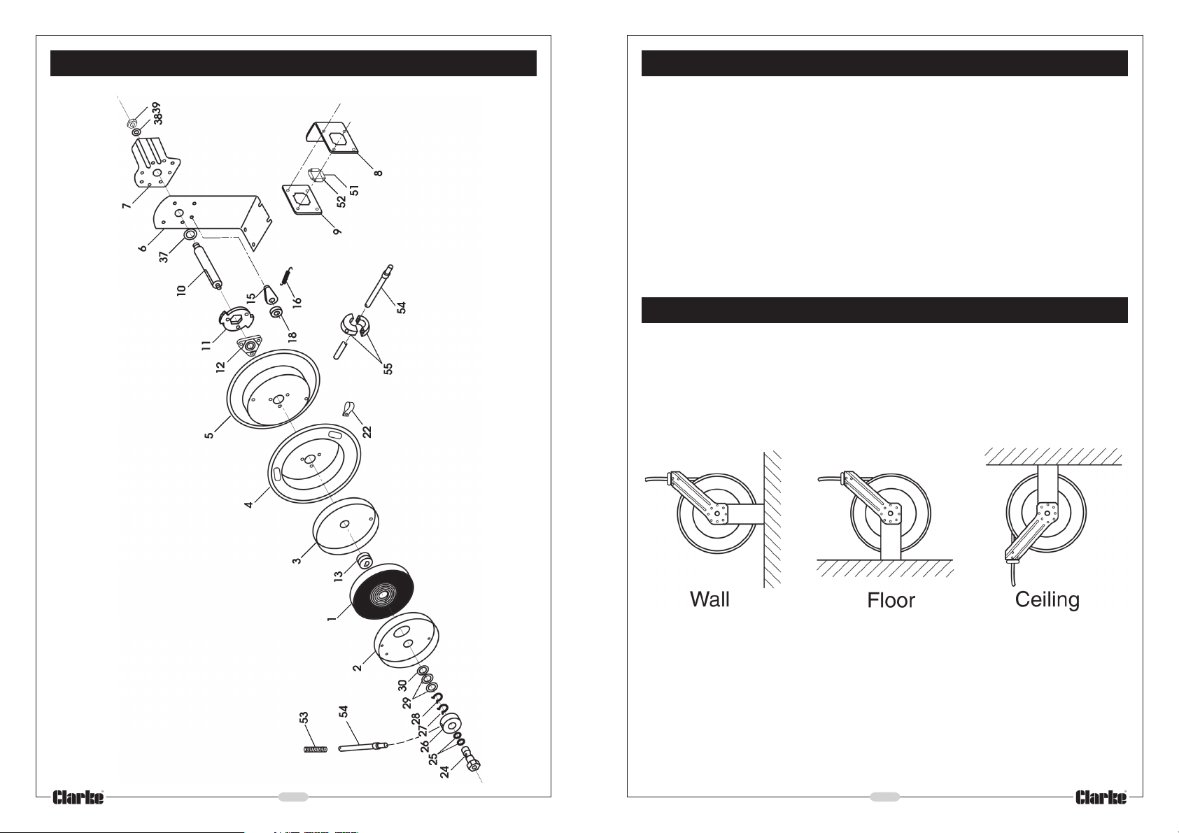
PARTS LIST
Thank you for purchasing this Clarke Hose Reel.
Please read this instruction leaflet carefully before installation, and ensure it is
maintained according to this schedule. In doing so, the Reel will provide you with
many years of satisfactory service.
GUARANTEE
This CLARKE product is guaranteed against faulty manufacture for a period of
12 months from the date of purchase. Please keep your receipt as proof of
purchase.
This guarantee is invalid if the product is found to have been abused or
tampered with in any way, or not used for the purpose for which it was
intended.
Faulty goods should be returned to their place of purchase, no product can
be returned to us without prior permission.
This guarantee does not effect your statutory rights.
Please Note: Seals, Plastic Rollers and rubber Stopper are considered
to be normal wear items and as such are not covered by this warranty
No. Description Part No.
1 Spring CAR8M01
2 Spring Drum Inner CAR8M02
3 Spring Drum Outer CAR8M03
4 Hose Drum Inner CAR8M04
5 Hose Drum Outer CAR8M05
6 Base CAR8M06
7 Arm CAR8M07
8 Guide Plate CAR8M08
9 Guide Sub-Plate CAR8M09
10 Shaft CAR8M10
11 Locking Ring CAR8M11
12 Hub Bearing CAR8M12
13 Spring Core CAR8M13
15 Cam, Locking CAR8M15
16 Cam Spring CAR8M16
18 Spacer (6.6mm) CAR8M18
No. Description Part No.
PARTS & SERVICE CONTACTS
For Spare Parts and Service, please contact your nearest dealer,
or CLARKE International, on one of the following numbers.
22 Hose Clamp CAR8M22
24 Swivel Connector CAR8M24
25 O-Ring CAR8M25
26 Air Manifold CAR8M26
27 Circlip (18.5x1mm) CAR8M27
28 Circlip (19x2mm) CAR8M28
29 Spacer (19.5x1.5mm) CAR8M29
30 Spacer (25.5x1.5mm) CAR8M30
37 Spacer (19.5x2.5mm) CAR8M37
38 Washer M16 CAR8M38
39 Nut M16 CAR8M39
51 Roller CAR8M51
52 Roller axle CAR8M52
53 Guard Hose CAR8M53
54 Hose CAR8M54
55 Rubber Stop Block CAR8M55
- 2 -
PARTS & SERVICE TEL: 020 8988 7400
PARTS & SERVICE FAX: 020 8558 3622
or e-mail as follows:
PARTS: Parts@clarkeinternational.com
SERVICE: Service@clarkeinternational.com
- 7 -
Page 3
PARTS DIAGRAM
SAFETY PRECAUTIONS
• Never exceed the rated operating pressure for this device - 20bar (300psi)
• Eye protection should be used when assembling and using the hose reel.
• Take ALL precautions with respect to the use of compressed air.
Remember....compressed air can kill.
• Ensure all air connections are properly sealed using teflon tape or pipe sealant.
• Never allow the hose to retract freely, It should always be restrained to prevent
the air tool from whipping, with resultant damage to persons or property.
INSTALLATION
The Hose Reel may be mounted to a wall, floor or ceiling , as required. Ensure the
mounting hardware (not supplied) is of sufficient strength to support the hose and
Reel plus the force required to extend the hose.
The position of the Hose Guide bracket, (containing the roller supports), may be
changed depending upon the mounting position, as illustrated below.
- 6 -
To change the position of the Roller bracket, proceed as follows:
1. Pull out the hose a short distance and allow it to ‘latch’.
2. Remove the 4 nuts securing the Arm and Roller bracket to the hub, noting that
the bolts used are ‘coach bolts’.
3. Position the Arm with Roller bracket, as required, and reassemble to the hub.
NOTE: This may be a little tricky if the coach bolts fall out. By inserting one bolt and
securing with a washer and nut first, then turning the drum whilst inserting the
remaining bolts, will simplify the operation.
- 3 -
Page 4

OPERATION
B. Hose Replacement
Check Reel for correct operation, as follows:
Gently pull out the hose - a series of clicks will be heard, every half revolution of
the drum.
When a click is heard, release the hose. It should be held by the latch. Continue
to pull out the hose, and after a series of clicks, at various lengths, release it to
check the operation of the latch.
To release the latch, give the hose a brief tug, and allow the hose to retract,
under control, until the stopper rests on the hose guide.
MAINTENANCE
WARNING: Whenever servicing or carrying out maintenance tasks, ALWAYS
turn OFF the air supply to the Hose Reel and release any pressure in the line.
Periodically, check the hose for wear and damage, and the swivel fitting for leakage
using soapy water. Any damage or leaks should be repaired before further use. Swivel
seal and hose replacement tasks are carried out as follows:
A. Swivel Seal Replacement
Periodically, it will be necessary to
replace the swivel seals. This is
accomplished as follows:
1. Disconnect air inlet hose, then
undo and remove the hose swivel
connector (A).
2. Unscrew the two hose securing clips
(B).
3. Pull out the hose until the first set of
clicks is heard, and allow it to latch.
4. Remove the hose stop (C), then
gently unwind the hose from the
reel and thread through the hole in
the side of the drum .
NOTE: As the hose connector to the manifold is very tight, and held with teflon
tape, it is preferable to disassemble the connector block, i.e. remove the swivel
connector, as detailed in swivel seal replacement above. The manifold may then
be held in a vice in order to disconnect the hose.
Reassemble in reverse order, using teflon tape or a suitable sealer at the hose
connection.
IMPORTANT! If the rewind spring fails for any reason, it is strongly
recommended that, for safety reasons, it is replaced by a trained technician,
or returned to your Clarke dealer for repair.
1. Remove the air inlet connection,
if fitted, then undo the swivel
connector - ‘A’.
C. Hose Tension Adjustment
Increasing or decreasing hose tension is achieved by simply adding or taking off
wraps of hose from the reel. To do this, simply pull out the hose by approx. 2 metres
and allow to ‘latch’, then wrap the hose around the drum to increase tension.
Alternatively, remove a wrap to decrease tension.
2. Remove the circlip (C), which
secures the swivel connector (A)
to the manifold (B) and pull the
out the connector.
3. Replace the seals (O-Rings) on
the swivel connector, then
reassemble in reverse order.
- 5 -- 4 -
 Loading...