

Page 1
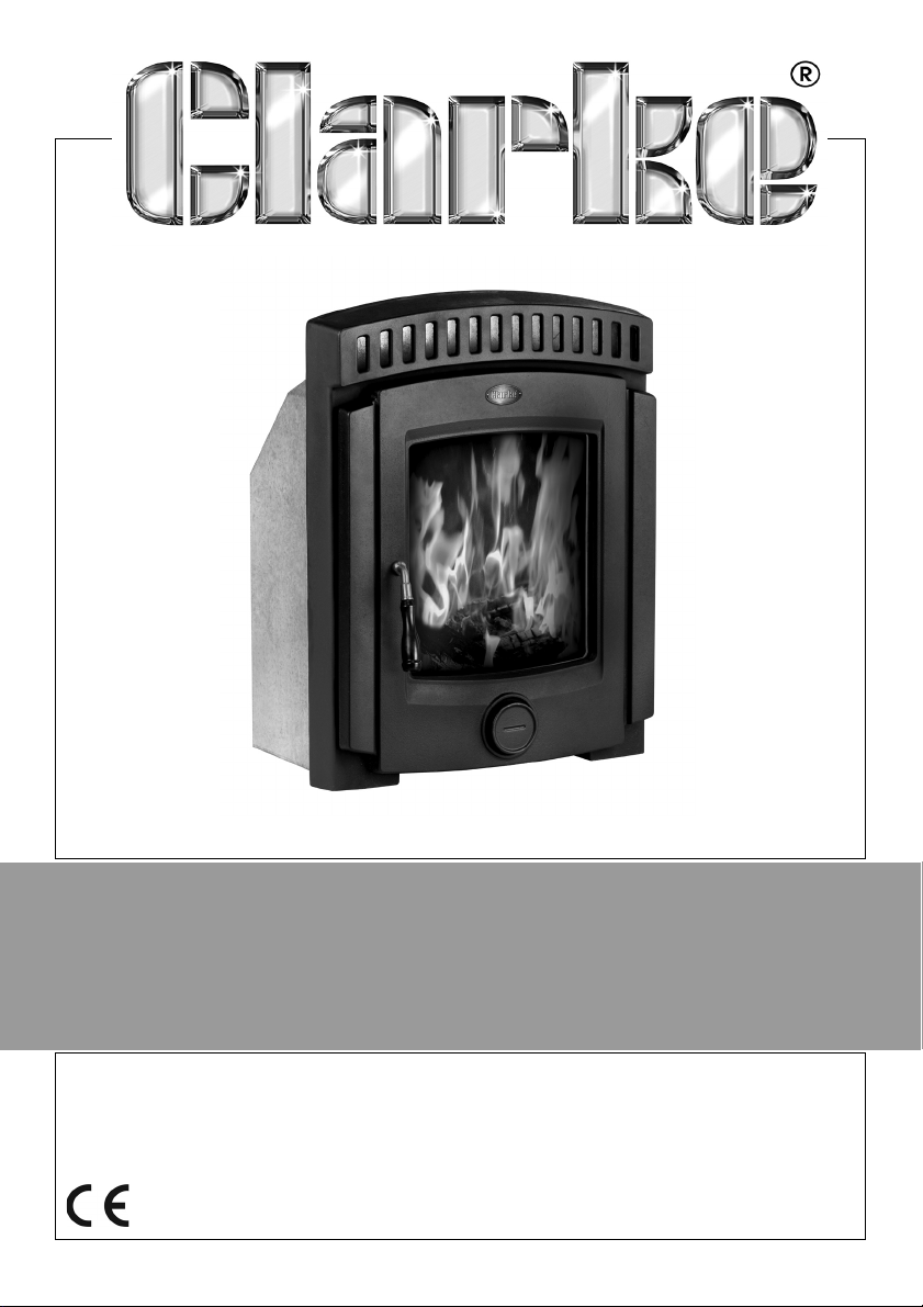
WARNING: Do not install the stove without reading this manual
INSERT STOVE
MODEL NO: BEAULIEU
PART NO: 6909915
INSTALLATION & MAINTENANCE
INSTRUCTIONS
ORIGINAL INSTRUCTIONS GC0917
Page 2
INTRODUCTION
Thank you for purchasing this CLARKE Stove.
Before attempting to use this product, please read this manual thoroughly and
follow the instructions carefully. In doing so you will ensure the safety of yourself
and that of others around you, and you can look forward to your purchase
giving you long and satisfactory service.
GUARANTEE
This product is guaranteed against faulty manufacture for a period of 12
months from the date of purchase. Please keep your receipt which will be
required as proof of purchase.
This guarantee is invalid if the product is found to have been abused or
tampered with in any way, or not used for the purpose for which it was
intended.
Faulty goods should be returned to their place of purchase, no product can
be returned to us without prior permission. This guarantee does not effect your
statutory rights.
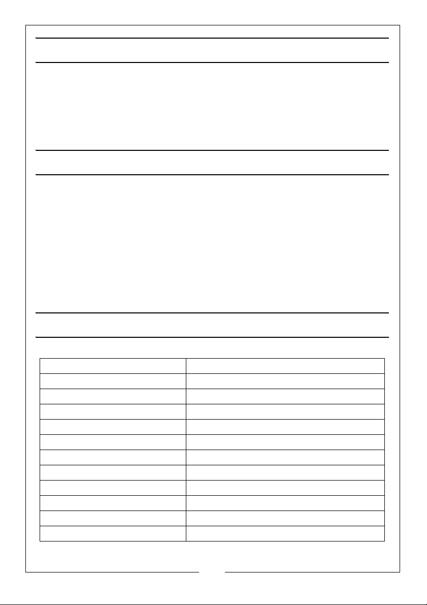
TECHNICAL SPECIFICATIONS
Weight 77.8 kg
Dimensions Front Surround 625 x 488 x 90 mm (H x W x D)
Dimensions of Rear Casing 513 x 397 x 267 mm (H x W x D)
Door Opening 287 x 318 mm
Fuel Wood or solid fuel (Ancit)
Nominal Heat Output 4.7 kw (16000 BTU) wood/5.0 (17000 ancit)
Space Heating Output 4.7 kw (16000 BTU) wood/5.0 (17000 ancit)
Energy Efficiency 78.5% (wood) 75.7%% (ancit)
Measured CO@13% Oxygen 0.28% (wood) / 0.18% (ancit)
Flue Diameter 125 mm
Flue Mass Flow 3.6 g/sec (wood) / 4.0 g/sec (ancit)
Recommended chimney draft 12 Pa
2
Parts & Service: 020 8988 7400 / E-mail: [email protected] or [email protected]
Page 3
INSTALLATION OF THIS PRODUCT
READ ALL THE INSTRUCTIONS CAREFULLY BEFORE INSTALLATION
WARNING: AN ACCREDITED HEATING ENGINEER MUST CARRY OUT THE
INSTALLATION OF THIS STOVE. ALTERNATIVELY, SHOULD A NONACCREDITED ENGINEER UNDERTAKE THE INSTALLATION, YOUR LOCAL
BUILDING CONTROL OFFICER WILL BE REQUIRED TO APPROVE THE
COMPLETED INSTALLATION UNDER BUILDING REGULATION “J”. IT IS AN
OFFENCE UNDER UK LAW, NOT TO COMPLY WITH THIS MANDATORY
REQUIREMENT.IF THE STOVE IS NOT FITTED CORRECTLY BY AN APPROVED
PERSON, IT COULD RESULT IN A HOUSE FIRE OR CARBON MONOXIDE
POISONING.
CAUTION: The instructions cover the basic principles to ensure
satisfactory installation of the stove, although detail may need slight
modification to suit particular site conditions. In all cases the installation
must comply with current Building Regulation ‘J’, Local Authority Byelaws, European and National standards and any other specifications or
regulations as they affect the installation of the stove.
CAUTION: The information contained in this manual includes extracts
from the Building Regulations 2000 “Approved Document J”
(Combustion Appliances and Fuel Storage Systems), updated October
2010. This guidance information in no way replaces your responsibility
as an installer or end user to comply with the appropriate standards.
CAUTION: THIS STOVE MUST BE CONNECTED TO A SUITABLE FLUE OUTLET.
Due to high temperature this stove should be located well away from
furniture and curtains. Children and adults should be alerted to the
hazards of hot surfaces. Young children should be carefully supervised
when they are in the same room as the stove. Do not place clothing or
other flammable material on or near the stove. Keep the stove area
clear of combustible materials, flammable liquids or vapours.
CAUTION: DO NOT OVERFIRE - it is possible to fire the stove beyond its
design capacity. This could damage the stove, so watch for signs of
overfiring - if any part of the stove starts to glow red, the stove is in an
overfire situation and the controls should be adjusted accordingly.
Never leave the stove unattended for long periods without first
adjusting the controls to a safe setting. Careful air supply control should
be exercised at all times.
CAUTION: FIRES CAN BE DANGEROUS - Always use a fireguard in the
presence of children, the elderly or the infirm. The fireguard should be
manufactured in accordance with B.S. 6539 - Fireguards for use with
solid fuel appliances.
3
Parts & Service: 020 8988 7400 / E-mail: [email protected] or [email protected]
Page 4
WARNING: THIS STOVE WILL BE HOT WHEN IN OPERATION AND DUE CARE
SHOULD BE TAKEN. THICK GLOVES SHOULD BE USED TO OPERATE THE
PRIMARY/SECONDARY CONTROLS OR REACHING INSIDE THE STOVE TO
POSITION FUEL OR REMOVE ASH.
CAUTION: CARBON MONOXIDE POISONING CAN BE FATAL. CARBON
MONOXIDE DETECTORS TO BS EN 50291 ARE AVAILABLE FOR USE IN
DOMESTIC PREMISES AND DETAILS ARE AVAILABLE IN THE OFFICIAL
HETAS GUIDE THAT CAN BE VIEWED ON THEIR WEBSITE AT
WWW.HETAS.CO.UK. DUE CONSIDERATION SHOULD BE GIVEN TO THE
DANGERS OF CARBON MONOXIDE POISONING FOLLOWING
INCOMPLETE COMBUSTION OF SOLID FUELS IN AN ENCLOSED SPACE.
SEE PAGE 17 OF THIS BOOKLET.
GENERAL SAFETY RULES
1. Always read and understand the manual before installing and
commissioning the stove.
2. Always ensure the stove is installed in accordance with local regulations.
3. Always ensure that the stove is correctly installed and positioned as
described under POSITIONING AND INSTALLATION on page 6, and that the
immediate area is kept clear.
4. Always check for damage before using the stove. Check for breakage of
parts and any other condition that may affect the stoves performance.
Any damage should be properly repaired or the part replaced. If in doubt,
DO NOT use the stove. Consult your local dealer.
5. Always keep children and visitors at a safe distance from the stove.
6. Never direct any kind of liquid on to the stove, particularly when it is hot.
7. Never use petrol or other flammable liquids for fire starting.
8. Never use the stove to incinerate materials other than recommended fuels.
9. Never carry out any modifications to this product. If experiencing difficulty
of any kind consult your local dealer.
10. The installation of the stove and chimney MUST comply with all National,
European and local building regulations. It is the responsibility of the owner
and the installer to ensure that the installation complies.
11. All rooms where a stove is situated must have a non-motorised air vent.
Refer to details contained in the Building Regulations.
4
Parts & Service: 020 8988 7400 / E-mail: [email protected] or [email protected]
Page 5
DETERMINING A SUITABLE CHIMNEY
NOTE: THE STOVE IS DESIGNED TO BE INSTALLED IN A SUITABLY PREPARED
FIREPLACE RECESS AND CONNECTED TO A SIMILARLY PREPARED
CHIMNEY. SEE INSTALLATION AND POSITIONING.
This stove is a radiant room heater and must be connected to a chimney of
the proper size and type. The chimney must have a cross sectional area of at
least 124 cm
Never connect to a smaller size chimney. Do not connect to a chimney
serving another appliance. Minimum chimney height 4.5 meters from floor on
which stove is installed.
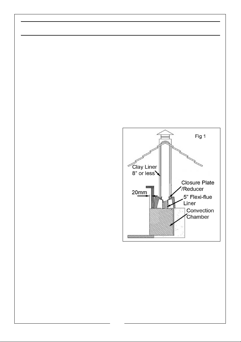
It is recommended that a flue liner of diameter 150mm be used to line the
chimney and the liner should be approved for use with solid fuel. See Fig.1.
It is permitted to connect using a
closure plate and a connection
piece from the stove to the closure
plate (see Fig 1), provided that the
chimney is of sound construction with
no leaks or cracks, a clay flue liner
has been used that can withstand up
to 1000
diameter no greater than 200mm.
IMPORTANT: ALL FLUE INSTALLATIONS
ARE THE RESPONSIBILITY OF THE
CUSTOMER.
The stove must be connected to a
chimney with a minimum continuous
draught of 12 Pascal’s (.05” WG).
Poor draught conditions will result in
poor performance.
2
or a diameter of at least 150mm.
o
C, the clay liner has a
5
Parts & Service: 020 8988 7400 / E-mail: [email protected] or [email protected]
Page 6

POSITIONING AND INSTALLATION
IMPORTANT: Building Regulation “J” is the Government approved document
covering the installation of solid fuel stoves.
In England and Wales there are only two routes to legally install a domestic
solid fuel or wood burning appliance. In other parts of the UK there are
variations in legislation and processes.
You can either:
• Use a registered installer who can self certify that the work he does
complies with the relevant Building Regulations; or
• The consumer applies to their local authority building control department
for a building notice, and pays the appropriate fee.
It is generally worthwhile to use a HETAS registered installer who will supply a
Certificate of Compliance as a record of the job and that it complies with
Building Regulations. A copy of the certificate is forwarded to HETAS who notify
the local authority on your behalf.
Failure to notify the work through the registration scheme (in this case HETAS) or
directly to the local authority can lead to enforcement. It can also cause
problems for future house sales if there is no official record of a compliant
installation. All local regulations, including those referring to National and
European Standards need to be complied with when installing this appliance.
For specific guidance when stoves are being installed in homes with thatched
roofs, please refer to the SOLIFTEC website at:
www.soliftec.com/installation.htm
SUPPORTING HEARTH
The hearth should be able to accommodate the weight of the stove and flue
components. The stove should stand on a hearth made of non-combustible
board/sheet material or tiles at least 12mm thick, if the stove has been tested
to an applicable standard to verify that it cannot cause the temperature of
the upper surface of the hearth to exceed 100
Constructional hearths should be made of solid, non-combustible material
such as concrete or masonry, at least 125mm thick, including the thickness of
any non-combustible floor and/or decorative surface.
Specific guidance for surfaces on which the stove may be allowed to stand is
given in Approved Document ‘J’ and must be followed.
6
Parts & Service: 020 8988 7400 / E-mail: [email protected] or [email protected]
o
C.
Page 7
MATERIAL CLEARANCES
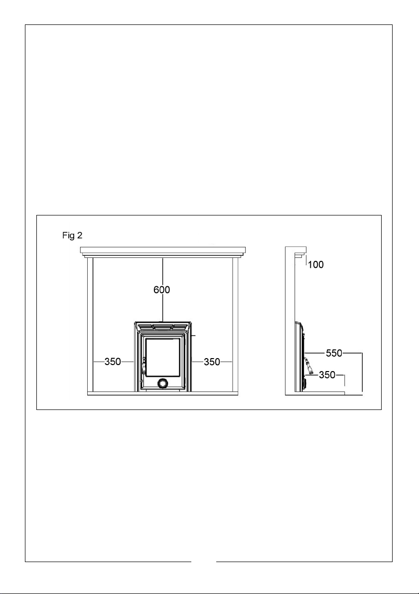
This stove must be installed in a recess which should not contain any
combustible materials. Wooden battens and plaster board should not be used
within the clearance given for combustibles. The minimum clearance to
combustibles required is 600mm to the top, 350mm to the sides, 550mm
directly to the front and 350mm to any combustible flooring.
If the mantelpiece protrudes further than 100mm from the fireplace, then it will
be necessary to have further clearance to the top of the stove. The distance
the mantle protrudes past the 100mm should be added to the clearance.
For example, if the mantle protrudes 200mm, the clearance to the mantle
should be 650mm. (See Fig 2).
If there is a studded wall surrounding the fireplace as in Fig 2, ensure the
clearances in this Fig are adhered to.
.
MINIMUM DISTANCE TO COMBUSTIBLE MATERIALS
NOTE: Combustible material refers to any material that will degrade when
subjected to heat e.g. plaster.
Due to the heat of a hot stove, a suitable fire guard should always be used to
provide additional protection. Never allow young children to be left
unsupervised in a room containing a hot stove.
Note; If in doubt, refer to the Building Regulations 2000 Approved Document
“J”.
7
Parts & Service: 020 8988 7400 / E-mail: [email protected] or [email protected]
Page 8

THE CHIMNEY
The stove is supplied with a flue pipe connector complete with fixing screws.
The stove should never be connected to a shared chimney/flue system.
Flue pipes with a smaller cross-sectional area than that of the stove outlet
should never be used. Flue pipes must not project into the chimney connector,
such as to cause a restriction to the gas flow.
Sizes of flues in chimneys are stipulated in Table 2 of the Building Regulations
2000 Approved Document “J” as follows:
• Stoves under 20kW rated output which burn smokeless or low volatile
fuel require a minimum flue size of 125mm diameter (or rectangular flues
having the same cross-sectional area and a minimum dimension not less
than 100mm for straight flues or 125mm for flues with bends or offsets.
Liners should be installed in accordance with their manufacturer’s instructions.
Appropriate components should be selected to form the flue without cutting
and to keep joints to a minimum. Bends and offsets should be formed only with
the matching factory-made components. Liners need to be placed with the
sockets or rebate ends uppermost to contain moisture and other condensates
in the flue. Joints should be sealed with fire cement, refractory mortar or
installed in accordance with their manufacturers instructions. Ensure the joints
are completely sealed as air leakage will lead to poor performance. Avoid
having more than two bends in the flue system. Any offset between bends
should be minimised and the flue should be equipped with suitable access
doors for inspection & cleaning. For further detail refer to Building Regulations
document “J”.
A range of suitable flue pipes, cowls and fire cement are available from your
Clarke dealer.
Special methods are required when passing through a wall or ceiling. Please
refer to your local building regulations and/or fire department. Refer to
Building Regulations Document “J”.
CAUTION: THIS STOVE MUST NOT BE INSTALLED INTO A CHIMNEY THAT
SERVES ANY OTHER HEATING APPLIANCE. THERE MUST NOT BE AN
EXTRACTOR FAN FITTED IN THE SAME ROOM AS THE STOVE, AS THIS CAN
CAUSE THE STOVE TO EMIT FUMES INTO THE ROOM.
FLUE HEIGHT
The chimney height and the position of the chimney should conform to the
Building Regulations document “J”. Flues should be high enough to clear the
products of combustion. The height necessary for this will depend on the type
of the appliance, the height of the building, the type of flue and the number
of bends in it, and an assessment of local wind patterns. However, a minimum
8
Parts & Service: 020 8988 7400 / E-mail: [email protected] or [email protected]
Page 9
flue height of 4.5m could be satisfactory if the guidance in paragraphs 2.10 to
2.12 of the Approved Document “J” is adopted.
FIG 3
As an alternative approach, the calculation procedure within BS EN 13384-1
(2005) can be used as the basis for deciding whether a chimney design will
provide sufficient draught. If in doubt, consult the Building Regulations.
The outlet from a flue should be above the roof of the building in a position
where the products of combustion can discharge freely and will not present a
fire hazard, whatever the wind conditions.
BENDS IN FLUES
Openings for inspection & cleaning should be formed using purpose factorymade components compatible with the flue system, having an access cover
that has the same level of gas-tightness as the flue system and an equal level
of thermal insulation.
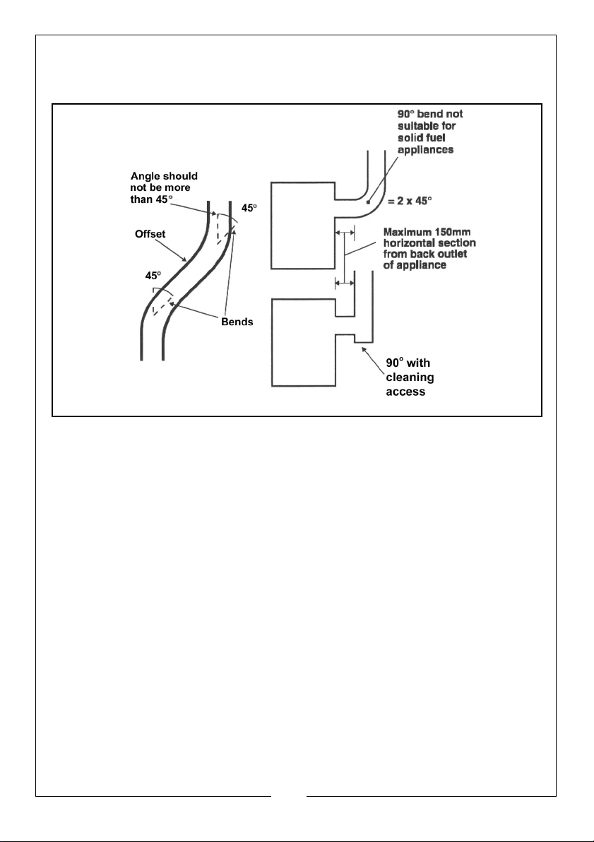
Offsets in flues are only acceptable if the following rules are respected:
• The chimney system shall have no more than 4 bends in total; - 2 bends in
the chimney and 2 bends in the flue pipe connection.
• The offset shall provide a change of direction no more than 45 degrees
from the vertical.
• The run of the chimney between bends shall not exceed 20% of the total
chimney length.
9
Parts & Service: 020 8988 7400 / E-mail: [email protected] or [email protected]
Page 10

Maximum length of horizontal flue must not exceed 150mm (6”).
INSPECTION & CLEANING
Check that the chimney is in good condition, dry and free from cracks and
obstructions. The diameter of the chimney should not be less than 150mm and
not more than 230mm. If any of these requirements are not met, the chimney
should be lined by a suitable method.
The chimney must be swept before connection to the stove. Where the
chimney is believed to have previously used; it is possible that the higher flue
gas temperature from the stove may loosen deposits that were previously
firmly adhered, with the consequent risk of flue blockage. It is therefore
recommended that the chimney be swept a second time within a month of
regular use after installation.
Assuming that when the stove is first installed, the chimney is clean, and sound,
then the chimney flue should be inspected part way through the burning
season to establish the regularity of sweeping required. If you have any doubts
about the suitability of your chimney, consult your local dealer/stockist.
If there is no existing chimney, then a prefabricated block chimney in
accordance with Building Regulations Approved Document J, or a twinwalled insulated stainless steel flue to B.S.4543 can be used. These chimneys
must be fitted in accordance with the manufacturer’s instructions and Building
Regulations.
FLUE DRAUGHT
A flue draught of minimum 1.2mm to a maximum 2.5mm water gauge is
required for satisfactory stove performance. The flue draught should be
checked under fire at high output. If it exceeds the recommended maximum,
a draught stabiliser must be fitted so that the rate of burning can be controlled
to prevent over-firing. If the reading is less than the recommended minimum,
then the performance of the stove will be compromised.
AIR FOR COMBUSTION
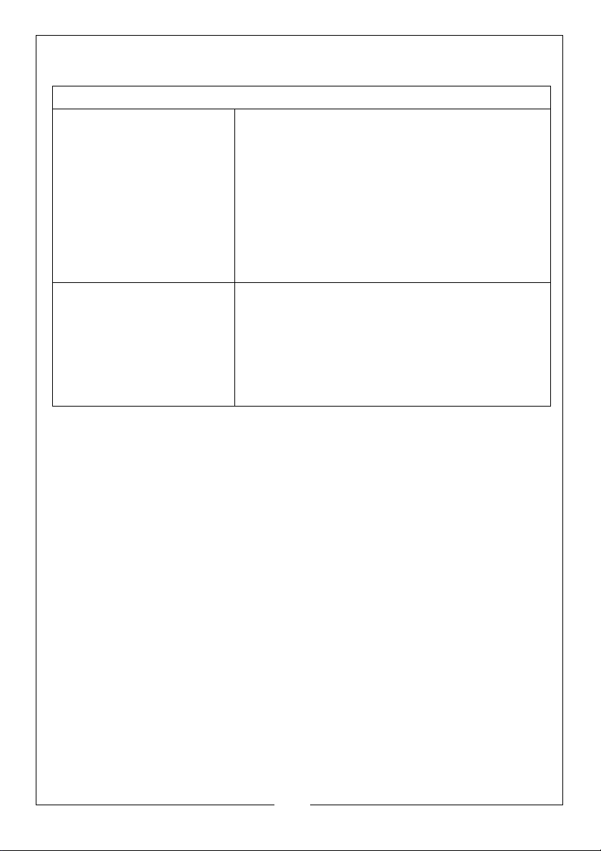
Any room or space containing a stove should have a permanent air vent
opening of at least the sizes shown in the table below. For stoves designed to
burn a range of different solid fuels, the air supply should be designed to
accommodate burning the fuel that produces the highest heating output.
There must always be a permanent means of providing air for combustion into
the room in which the fire is installed. A permanent vent with a total free area
of at least 550mm
directly to the outside air or an adjacent room which itself has a permanent
vent of the same size direct to the outside air. The fitting of an extractor fan to
either of these rooms is not permitted.
Parts & Service: 020 8988 7400 / E-mail: [email protected] or [email protected]
2
for every kW rated above 5kW should be connected
10
Page 11
CONNECTION TO THE CHIMNEY
Stove Air Supplies
Stove with flue draught
stabiliser
Stove with no flue draught
stabiliser
This MUST be carried out by an accredited/competent person and/or
approved by your local Building Control Officer before using the stove.
Any existing flue must be in good condition with suitable access for collection
and removal of debris. Details of suitable linings for use with solid fuel are given
in the official HETAS guide that can be viewed on their website at
www.hetas.co.uk.
It is also important that suitable flue pipe complying with Building Regulations is
used to connect the stove to the chimney flue and that suitable access is
provided into the flue for regular inspection and sweeping of the flueways.
Chimneys should be as straight as possible and horizontal runs should be
avoided. Refer to the typical installation diagrams. Flue connections must be
well sealed.
The chimney may be swept through the door opening, but if it is not possible
to pass the sweeps brush through the stove, a soot door will be necessary. This
may be either in the actual brickwork of the chimney or fitted in the register
plate. Suitable positions of soot doors are shown in Figure 4.
Important! Never fit an extractor fan in the same room as this stove.
Permanently open vents as below:
3
If design air permeability>5.0m
/(h.m2) then
300mm2/kW for first 5kW of appliance rated
output
2
850mm
/kW for balance of appliance rated
output
3
If design air permeability<5.0m
2
/kW for balance of appliance rated output
mm
/(h.m2) then 850
Permanently open vents as below:
3
If design air permeability>5.0m
2
/kW of appliance rated output above 5kW
mm
If design air permeability<5.0m
2
/kW for balance of appliance rated output
mm
/(h.m2) then 550
3
/(h.m2) then 550
11
Parts & Service: 020 8988 7400 / E-mail: [email protected] or [email protected]
Page 12
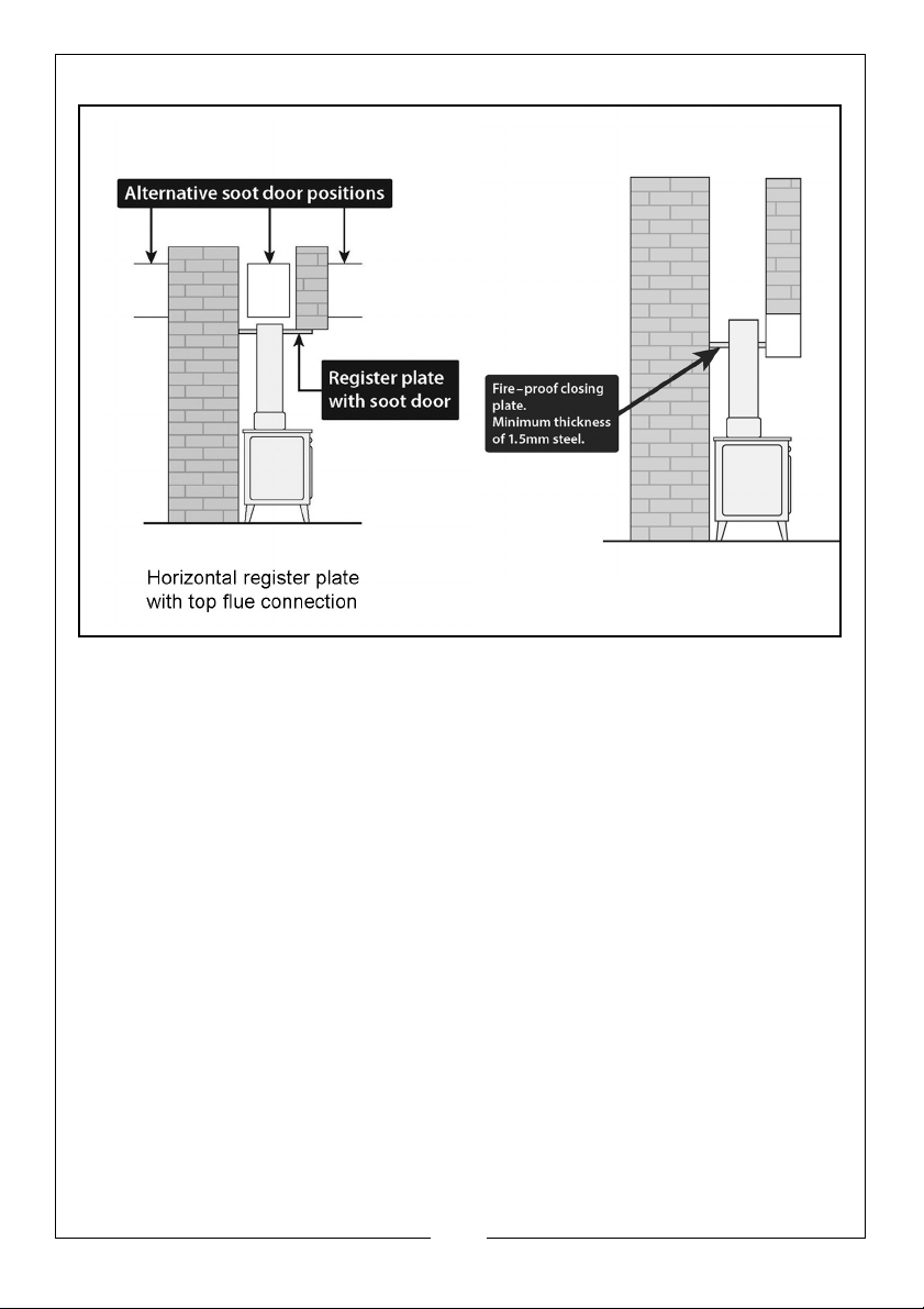
FIG 4
A non-combustible register plate minimum 1.5 mm thick should be fitted to all
installations between the flue and the building structure. It’s suitability and fit
should be checked by a qualified stove installation engineer against the
current Building Regulations App”J”.
CLEANING THE FLUE
Access for cleaning the flue should be incorporated in the system other than
through the appliance (e.g. a soot door or access through a register plate).
Purpose-made soot doors and inspection lengths are available from the
Clarke range. Ensure that the whole length of the flue can be reached from
the soot door.
If necessary, seek professional advice.
12
Parts & Service: 020 8988 7400 / E-mail: [email protected] or [email protected]
Page 13
UNPACKING
WARNING: DUE TO THE WEIGHT OF THE STOVE IT IS RECOMMENDED THAT
TWO PEOPLE PERFORM THE UNPACKING.
Unpack the stove and remove packing materials. Open the door and remove
all loose items from inside the stove.
Before assembling, please check contents against the following list and advise
your dealer immediately if any parts are missing. Refer also to parts list &
diagram on pages 28 & 29.
• 1 x Cast Iron Inset Stove c/w Steel Casing
•1 x Flue Collar
• 1 x Log Retainer
• 1 x Ash Pan
• 1 x Ash Pan Handle Tool
• 5 x Parts Packs containing:
Door Handle
Shake Handle
Self-tapping screw
Allen wrench
Collar fixing screws c/w wrench
TOOLS REQUIRED
•x-head screwdriver
• 10mm wrench
A full range of flue pipes and fire cement is available from your Clarke dea.ler.
Recycle unwanted materials instead of disposing of them as waste.
All tools, accessories and packaging should be sorted, taken to a
recycling centre and disposed of in a manner which is compatible
with the environment.
13
Parts & Service: 020 8988 7400 / E-mail: [email protected] or [email protected]
Page 14
PREPARATION
After removing the stove from the crate, open the door and remove the loose
items and packing.
• Prior to installation, removal of the internal components is required in
order to access the fixings connecting the base of the stove to the outer
casing and to reduce the weight during installation.
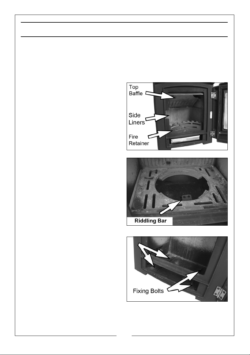
1. Remove the left/right side liners
which are loose and just need to
be lifted clear of the grate
support plate.
2. Remove the loose baffle by lifting
the front edge until it hits the top
of the stove and then slide it
forward. Drop the rear edge and
the baffle will slide down.
3. Next, remove the riddling grate by
pushing it from underneath. The
riddling bar is fixed to the grate
with two bolts which need to be
undone.
4. Remove the flue connector with
its gasket, by removing the two
bolts, nuts and washers.
5. Remove the grate support plate
by lifting it from underneath.
• This will allow access to four
fixing bolts which attach the
stove to the outer steel casing.
6. Lift away the rear liner and tilt it so
that it will pass through the door
opening.
Finally, remove the four bolts,
allowing the insert stove to be removed from the external casing.
14
Parts & Service: 020 8988 7400 / E-mail: [email protected] or [email protected]
Page 15
FITTING AND ASSEMBLY
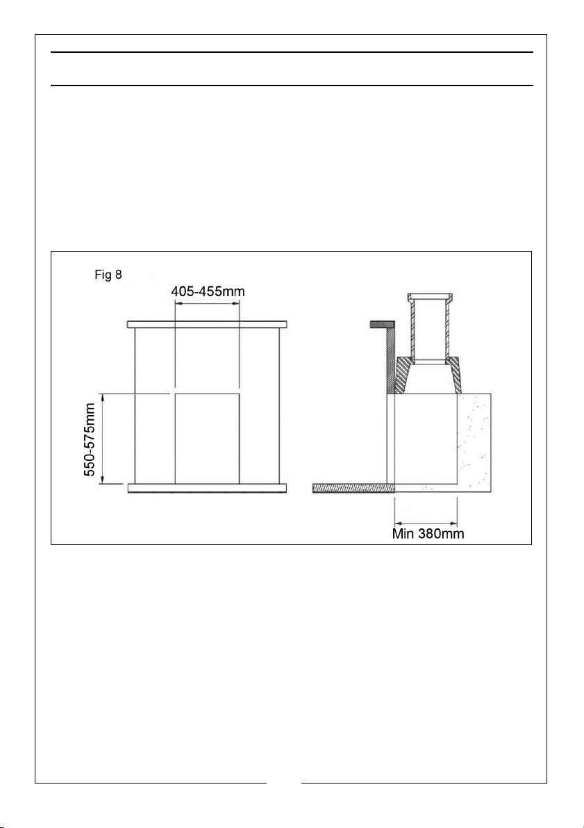
1. Prepare the fireplace area with fireback or millner brick removal. Ensure the
opening is suitable for fitting of the insert stove, i.e. remove the fire surround
trim if fitted. See Fig 8.
2. Ensure the floor area is level with the hearth, this area needs to be level as
the insert fire is screw fixed to the floor.
3. Lay the external casing into the opening and position it so that the front
edge protrudes 20mm past the front edge of the opening.
.
4. Mark the fixing location and drill the holes using a 5.5mm drill bit. Fix the
casing to the floor using the self tapping screws provided.
5. With the flue liner installed in the chimney, line it up with the flue connector
and drill appropriate holes for a self tapping screw.
6. Secure the flue to the connector using chosen fixings (not supplied).
7. Ensure a good seal is achieved with the flue connector by using fire
cement.
Lift the stove into the external casing with all internal parts removed. The stove
can be lifted into the casing and then pushed into the final position while
taking care to lift the front edge not to damage the hearth. Fix it in position
using the fixing bolts in the base of the stove.
15
Parts & Service: 020 8988 7400 / E-mail: [email protected] or [email protected]
Page 16
RE-ASSEMBLY
Fit the individual components back into the stove in the following order:
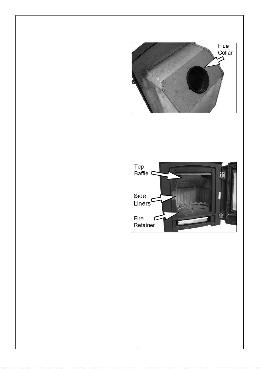
1. Fit the flue connecting collar to
the stove box using the screws,
washer and nuts provided.
2. Stand the rear firebrick in position.
3. Tilt the grate support up on one
side and pass it through the door
opening, it should then rest on the
supports above the floor of the
stove.
4. The grate lays into the grate
support after reconnecting the riddling control tongue with the two bolts.
5. Hold the top baffle by the ‘L’ shaped end with the fold turned up.
Manoeuvre it diagonally through the door opening and then drop the rear
edge to the rear of the stove. Lift the ‘L’ shaped edge up over the ‘L’
shape on the side castings.
6. Move the baffle as far as possible
to the front and top. Then lift the
back edge up and allow the
baffle to rest on the top rib on the
back and in the ‘L’ shape on the
side castings.
• Note: The row of secondary air
holes must be visible
underneath the baffle.
7. Stand the side firebricks in position
8. Set the fire retainer into the slots provided.
Attach the handle to the door using the screwed centre spigot.
COMMISSIONING THE STOVE
1. Check the soundness of seals, castings and joints.
2. Check the operation of the air controls.
3. Carry out a smoke draw test by warming the flue with a blow-lamp, or
similar, for about 10 minutes. Place a smoke pellet on the centre of the
firebox, with the air controls open. Smoke should now be drawn up the flue
and be seen to exit from the flue terminal.
• Complete the test with all doors and windows closed in the room where
the appliance is fitted.
16
Parts & Service: 020 8988 7400 / E-mail: [email protected] or [email protected]
Page 17

If there are any extractor fans in adjacent rooms, the test must be repeated
with the fans running on maximum and interconnecting doors open.
4. Check the effect of any ceiling fans during the test.
5. If the test fails, re-check the suitability of the flue system and ventilation. An
inadequate air supply to the room is potentially dangerous.
6. Light the stove and slowly increase the temperature to operating levels.
7. Ensure no combustion products enter the room.
8. When the appliance reaches operating condition carry out a smoke
spillage test with a smoke match or pellet around the opening.
9. If excessive smoke spillage occurs allow the appliance to cool and recheck the flue system and ventilation.
CARBON MONOXIDE ALARMS
Due consideration should be given to the dangers of carbon monoxide
poisoning following incomplete combustion of solid fuels in an enclosed
space. Carbon monoxide detectors to BS EN 50291 are available for use in
domestic premises and details are available in the official HETAS guide that
can be viewed on their website at www.hetas.co.uk.
Where a new or replacement fixed solid fuel appliance is installed in a
dwelling, a carbon monoxide alarm should be provided in the room where
the appliance is located.
Carbon monoxide alarms should comply with BS EN 50291:2001 and be
powered by a battery, designed to operate for the working life of the alarm.
The alarm should incorporate a warning device to alert users when the
working life of the alarm is due to pass. Mains-powered BS EN 50291 Type A
carbon monoxide alarms with fixed wiring (not plug-in types) may be used as
alternative applications, provided they are fitted with a sensor failure warning
device.
The carbon monoxide alarm should be located in the same room as the stove:
• on the ceiling at least 300mm from any wall or, if located on a wall, as high
up as possible (above any doors and windows) but not within 150mm of
the ceiling and:
• between 1m and 3m horizontally from the stove.
Further guidance on the installation of carbon monoxide alarms is available in
BS EN 50292:2002 and from manufacturers instructions. Provision of an alarm
should not be regarded as a substitute for correct installation and regular
servicing.
17
Parts & Service: 020 8988 7400 / E-mail: [email protected] or [email protected]
Page 18
USING YOUR STOVE
THE CONTROLS
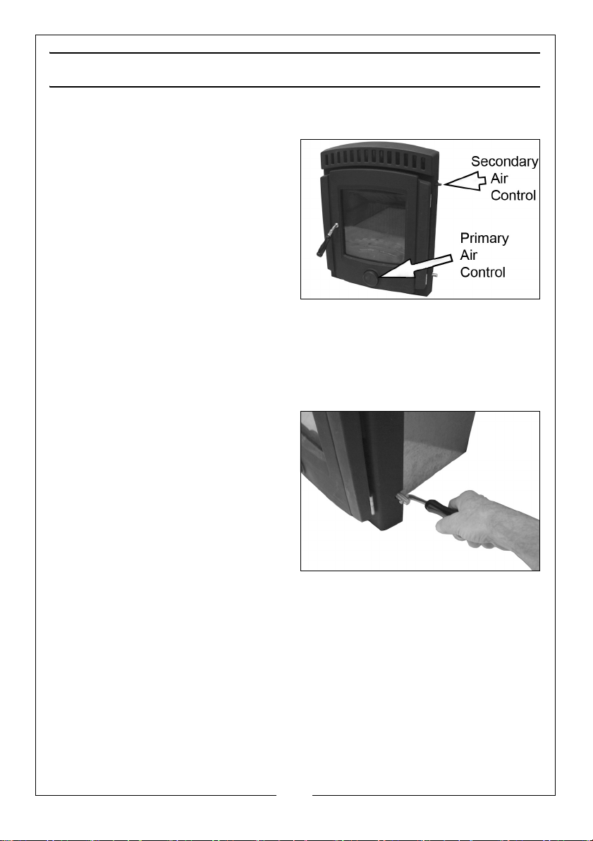
The amount of heat emitted by the
stove is regulated using the primary
air control at the bottom of the door.
• When screwed in, this reduces
the airflow through the stove
and dampens the combustion.
• When screwed out the airflow is
increased which increases the
combustion rate.
Secondary air is also inducted via an
upper air control at the top of the stove. This control can also be used as an
“air wash” facility and should help keep the door glass clear of combustion
deposits.
• The control can be moved to the side and corresponds to a series of
holes in the stove front.
A further control is provided for
riddling (moving) the grate panel to
dislodge any accumulation of loose
ash into the ash pan. This is operated
using the Shake Handle (supplied
loose), which is engaged with the
control rod when required.
• Moving the control rod to and
fro will rotate the grate while
twisting the control raises/
lowers the grate.
WOOD BURNING
When first igniting or after re-fueling, both the lower (primary) and upper
(secondary) controls should be fully opened. When the fire is burning
vigorously, more fuel should be added as required. When the stove body
becomes hot, the lower control should be closed. The combustion rate can
then be controlled by adjusting the position of the upper control.
SOLID FUEL
When first igniting or after re-fueling, both the lower (primary) and upper
(secondary) controls should be fully opened. When the fire is burning
vigorously, more fuel should be added as required. When the stove body
18
Parts & Service: 020 8988 7400 / E-mail: [email protected] or [email protected]
Page 19

becomes hot, the upper control should be closed. The combustion rate can
then be controlled by adjusting the position of the lower control.
Warning: THE TEMPERATURE OF THESE ITEMS DURING OPERATION COULD
CAUSE AN INJURY TO THE END-USER. AS THESE ARE INTENDED TO BE
ADJUSTED DURING OPERATION, IT IS RECOMMENDED THAT PROTECTIVE
GLOVES ARE WORN WHEN HANDLING THESE PARTS.
TYPES OF FUEL
This stove will function with wood or solid fuel, but in general all fuel should be
dry and timber should be well seasoned so as to have a moisture content
below 20%. The use of damp wood will result in more soot and tar deposits
being left in the chimney, flu and stove, and will not release heat if thermal
energy is being used to drive out moisture from the fuel.
Other fuels can be used together with wood, provided the base of the fire
remains as wood or compressed block fuels. Coal products can be added to
this provided the volume of coal products is less than that of other fuels
With solid fuels, there is less need to burn the stove hard after refuelling. The
rate of refuelling will also be less often than with wood.
Avoid using the stove to incinerate other materials including household waste.
Avoid using ‘green’ unseasoned wood, treated wood such as telegraph
poles, or plywood / chipboard containing glues and resins which pollute the
environment and cause the fire to burn too quickly.
Such materials can produce excessive tar or creosote which can be
damaging and in extreme cases cause a fire inside the chimney.
The dryness of wood can be assessed by looking at the end of the log. Radial
cracks, deep enough to be considered as splits should be present in dry,
seasoned logs.
The maximum length of fuel suitable for this stove is approx 30 cm so as to lay
flat over the embers, and logs of greater than 10 cm diameter should be split.
Confirm with your fuel provider as to which type will suit best. Larger fuels will
allow a greater draught in the firebox which will speed up combustion.
Household coal produces more ash & chimney deposits than smokeless fuels.
For further information on type and availability of fuel, the Solid Fuel
Association (http:/www.solidfuel.co.uk) serves as an advice centre to
domestic consumers including all aspects of fuel types.
The UK Smoke Control Areas website (http:/www.uksmokecontrolareas.co.uk)
defines the location of smoke controlled areas throughout England, Scotland,
Wales and Northern Ireland and lists all fuels which are authorised for use in
Smoke Control Areas. However, you should check with your local council to
confirm that you can use a stove in a smoke controlled area.
19
Parts & Service: 020 8988 7400 / E-mail: [email protected] or [email protected]
Page 20

INITIAL SEASONING
Following installation, and before regular use, the stove must be seasoned to
prevent cracking of the metal casting. This procedure should also be followed
if the stove has not been used for prolonged periods (during the summer
months for example), and is carried out as follows:
1. Light a small fire in the middle of the stove, well away from the sides.
2. Allow the stove to warm up slowly and evenly with the air controls almost
closed, avoiding intense flames.
3. Keep the fire burning for three hours or so, gradually increasing the size of
the fire using larger logs which will burn naturally but slowly, keeping the
stove on a low setting.
4. After a couple of days burning at this level, increase the brightness &
intensity of the fire gradually over the next 10 days.
Full strength fires should not be used until completion of approx 20 days of mild
use. Only from this time will the stove have been properly seasoned
It should be remembered that this procedure should be carried out at the
beginning of each season of use in order to remove the moisture retained by
the metal during the period of non-use.
When used for the first time the fireplace may smell a little, due to gas being
given off. The gas is not toxic but the room should be thoroughly ventilated.
Let the fire burn with a high draught until no smells can be detected.
Take care not to open the stove door too vigorously in case of causing smoke
spillage. If smoke spillage occurs after the fire door has been opened this
could be due to poor chimney draft. SEE TROUBLESHOOTING.
FIRE-LIGHTING WITH WOOD
1. Open the air controls.
2. Lay firelighters or rolled up newspapers on the grate with a reasonable
quantity of dry kindling wood. Place 2 or 3 small logs on top.
3. Light the newspaper or firelighters using a long taper and close the door.
4. When the fire is burning strongly, add further logs up to 10mm diameter.
5. When the stove is really hot, close the air controls as required. Ensure there
are lasting flames until the wood becomes charcoal.
FIRE-LIGHTING WITH SOLID FUEL
1. Open the air controls.
2. Lay firelighters or rolled up newspapers in the stove with a reasonable
quantity of dry kindling wood. Place a small quantity of solid fuel on top.
20
Parts & Service: 020 8988 7400 / E-mail: [email protected] or [email protected]
Page 21

3. Light the newspaper or firelighters using a long taper and close the door.
4. When the fire is burning strongly add further fuel.
5. When the stove is hot, reduce the opening of the air control.
6. The burn rate can be reduced by partially closing the air control.
REFUELLING
1. Always open the door slowly to avoid a sudden rush of intake air and
smoke escaping into the room and add fuel.
2. Open the air controls and leave open for a few minutes to allow the gasses
in the wood to burn before closing the air controls.
• The rate of refuelling and heat available are dependant upon individual
requirements based upon the user’s experience. When re-loading, it is
normally necessary to burn the stove fast initially, to drive off any gasses
and moisture, before closing the air vents to control the burn rate.
3. Ensure the door is kept closed to contain fumes except when lighting up,
re-fuelling or removing ash.
• It is not recommended to leave the stove alight at night or to continue
using the stove in mild weather which gives poor combustion leading to
a greater buildup of soot.
• If overnight burning is required, it can best be achieved by first driving off
any gasses or moisture as usual, following a full charge of fuel and then
closing the air vents fully. Experience will indicate the optimum setting.
However, by reducing the burn rate to such a level that the fire is still
burning the following day, the burning process creates heavy, tarry
chemicals which will become deposited on the inside of the flue or
chimney. This is an inefficient process which greatly increases the risk of a
chimney fire and makes it necessary to sweep the chimney more often.
FUME EMISSIONS
To avoid chimney problems, your fire should not be burnt slowly for longer than
12 hours without a period of fast burning.
Properly installed and operated, this stove will not emit fumes. Occasional
fumes from de-ashing and refuelling may occur. Persistent fume emission must
not be tolerated. If fume emission persists, the following immediate action
should be taken:-
1. Open doors and windows to ventilate room.
• Let the fire out, or eject and safely dispose of fuel from the stove.
2. Check for flue chimney blockage and clean if required.
21
Parts & Service: 020 8988 7400 / E-mail: [email protected] or [email protected]
Page 22

• Do not attempt to re-light the fire until the cause has been identified
and corrected.
ASH REMOVAL
Keep the stove free from a heavy buildup of ash. The frequency of this is
dependant upon the type and quality of fuel being used. Ash should be
removed before it builds up to the underside of the grate, at which point, the
grate would be burning hot on both sides, shortening its life expectancy.
When disposing of ashes, ensure they have cooled and always place in a
metal container. Be sure to remove the ash when the fire is at its lowest point,
such as first thing in the morning.
The Clarke Ash Can Filter is ideal for use in conjunction with the Clarke range
of vacuum cleaners, for collecting hot ash and debris from stoves.
22
Parts & Service: 020 8988 7400 / E-mail: [email protected] or [email protected]
Page 23
TROUBLESHOOTING
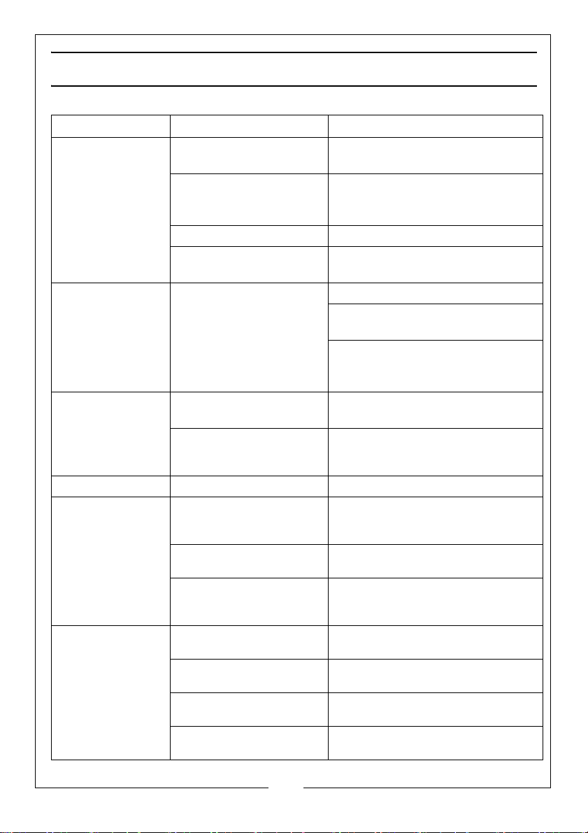
PROBLEM CAUSE SOLUTION
Fire difficult to
start.
Fire goes out.
Fire burns too
quickly.
Stove smokes
when lighting up.
Low heat output. Incorrect fuels. Use recommended fuels.
Smokes while
burning
Smoke spillage
when opening
door.
Wood green, too damp
Use recommended fuel.
or poor quality.
Logs are too large. When lighting, use small, dry
kindling. To maintain the fire use
split logs.
Air starvation Open air control.
Insufficient draught. Check that flue is not obstructed,
sweep flue if necessary.
Too much draught. Ensure the air control is closed.
Install a draught stabiliser. Consult
your dealer.
Do not continuously burn small
wood, sticks, carpentry offcuts,
plywood etc
Flue duct is cold. Burn paper and kindling wood to
increase heat.
Room is at negative air
pressure to the outside.
Draught is insufficient
Downdraught present.
Room is at negative
pressure to outside.
Chimney not tall enough to
be clear of roof line.
Poor sealing of flue-pipe
joints.
Flue is partially blocked with
soot.
House too tightly sealed.
In houses equipped with mechanical
ventilation, open a window until the
fire is well established.
Consult a chimney specialist. Check
that flue is not obstructed. Sweep if
necessary.
Install an anti-downdraught cowl.
Consult your dealer.
In houses equipped with mechanical
ventilation, an outside air intake must
be installed in the chimney.
Increase height of chimney.
Re-connect flue or replace jointing
material
Arrange to have chimney swept.
Ensure a fresh air supply is reaching
the stove.
23
Parts & Service: 020 8988 7400 / E-mail: [email protected] or [email protected]
Page 24

MAINTENANCE
CLEANING
The inside of the stove may require regular cleaning, especially during periods
of peak use, the frequency of this being indicated by experience. It is
advisable to wear a dust mask, protective gloves and safety glasses when
cleaning.
Use a stiff brush and industrial type vacuum cleaner to dislodge and remove
as much material as possible, starting at the top of the stove and working
down to the bottom. Particular attention should be given to the air inlet
controls which can become obstructed. A CVAC Ash Can Filter and vacuum
cleaner is ideal for this process.
GENERAL MAINTENANCE
Take this opportunity to check for any damaged parts inside the stove. In the
event of damage or broken components, replacements can be obtained
from Clarke Parts & Service. On no account should unauthorised spare parts
be used.
The stove and flueway should be inspected and maintained when in a cold
condition. No unauthorised modification of this product should be carried out.
This stove requires regular maintenance by a competent engineer.
STOVE BODY
The stove is finished with a heat-resistant paint which can be cleaned with a
soft brush. Wait until the stove has cooled down before doing this. This finish
can be renovated with Clarke stove paint, although the paint may not be an
exact match and it may be necessary to repaint the complete stove.
If the stove is purely ornamental, painting will provide a durable, attractive
finish. If the stove is used for heating, a high temperature heat resistant paint
(available from your Clarke dealer) must be used, in either aerosol or brush
applied form. Should rust become apparent, clean thoroughly with a wire
brush and apply a suitable anti-rust treatment.
During prolonged periods out of use, the air inlet should be left open and the
door left slightly ajar in order to circulate fresh air and discourage
condensation from forming which could encourage corrosion.
24
Parts & Service: 020 8988 7400 / E-mail: [email protected] or [email protected]
Page 25
FIRE ROPE
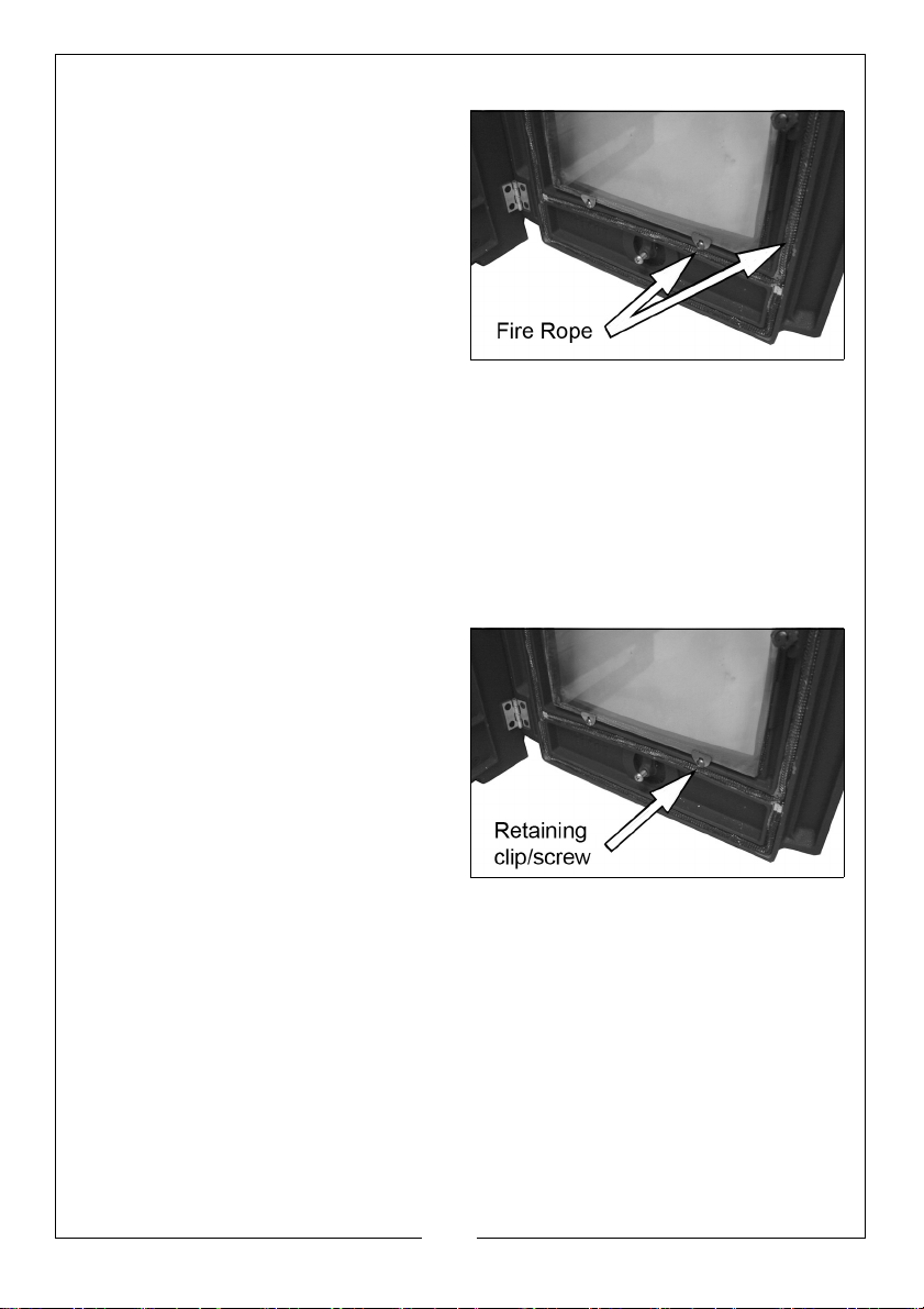
Check the rope around the door and
glass. If rope is becoming detached,
replace with rope approved for this
purpose.
Inspect the fireproof door seals where
fitted, to ensure there is an effective
seal around the door and re-fix it if
loose using stove rope adhesive. If in
poor condition it should be replaced.
GLASS PANELS
Clean any glass panels when cool, avoiding abrasive substances which could
scratch the glass and make subsequent cleaning more difficult. Wet logs
against a heated glass, a badly aimed poker or heavy slamming of the doors
could crack the glass panels. The glass will not fracture with heat. Never
replace any broken glass with glass NOT approved for use with stoves.
The window glass should remain clean during normal use but it can become
blackened if the stove is being operated with either damp fuels or at a slow
burn rate. The blackening may be dispersed by burning briefly at a much
higher temperature, or it may be cleaned off using specialist glass cleaner.
In the event of the glass being
broken, it can be removed by
unscrewing the retaining clips, taking
care not to damage the fireproof
seal. The replacement glass should
be carefully placed against the seal
and the retaining clips re-tensioned.
Take care to tension these evenly or
there is a risk of breaking the new
glass pane.
CHIMNEYS AND FLU-WAYS
It is important that the chimney, flu-ways and any connecting flue pipe are
swept regularly. This means at least once a year for smokeless fuels and at
least twice a year for wood and other fuels.
Only wire-centred sweep’s brushes fitted with a guide wheel should be used. If
it is not possible to sweep all parts of the chimney through the stove, ensure
there is adequate access to cleaning doors.
If the stove is fitted in place of an open fire, then the chimney should be swept
one month after installation to clear any soot falls which may have occurred,
due to the difference in combustion performance between the stove and the
open fire.
25
Parts & Service: 020 8988 7400 / E-mail: [email protected] or [email protected]
Page 26

The flue and chimney should be inspected for a buildup of deposits especially
following prolonged periods without use. The entire chimney/flue should be
swept frequently from top to bottom by a registered chimney sweep to
remove any buildup of soot etc, the frequency being dependant upon the
usage and the fuels being burnt. If the chimney is swept after a few weeks of
regular use, the condition found will give an indication of the frequency of
sweeping required. On an annual basis, the chimney is best swept just before
the main winter burning season.
HETAS recommends that chimney sweeping is best carried out by an
approved chimney sweep who will normally be a member of the National
Association of Chimney Sweeps or the Guild of Master Sweeps, details of
which can be found on the HETAS website, www.hetas.co.uk.
26
Parts & Service: 020 8988 7400 / E-mail: [email protected] or [email protected]
Page 27

ACCESSORIES
Refer to the Clarke website www.clarkeinternational.com for a full range of
Flue Pipes & Cowls for use with this classic cast iron stove. See also the
following accessories;
Fire Cement (1Kg tubs) Part No: 6910000
Ash Can Filter Part No: 6471130
Paper Briquette Maker Part No:1801617
Matt Black Stove Paint (500ml) Part No: 6910200
Electric Log Splitters;
Logbuster 5 Part No 3402030
Stand also available Part No 3402045
See also Logbusters 4, 6, 7 & 8
27
Parts & Service: 020 8988 7400 / E-mail: [email protected] or [email protected]
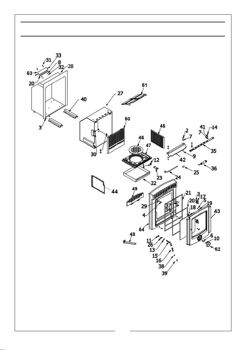
Page 28
Page 29
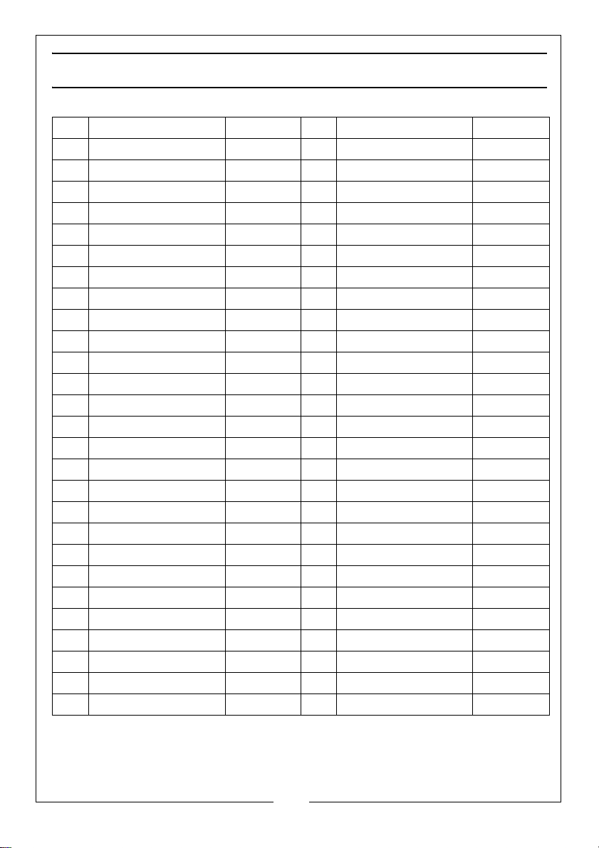
COMPONENT PARTS
POS DESCRIPTION CODE POS DESCRIPTION CODE
1 Bolt M6 x 10 CA0211 28 Steel Outer Shell CAWK02
2 Bolt M6 x 20 CA0213 29 Nut M6 CA0407
3 Hinge Screw CA0293 30 Bolt M6 x 50 GXGZ-1
4 Bolt M6 x 25 CA0275 31 Bolt M6 X 25 CA0275-1
5 Hex m/c Screw M6x8 CA0293-1 32 Nut M6 CA402-1
6 Air Control Spigot CA0267-02 33 ST Screw GXGZ-2
7 Spacer 6 dia x 18 CA0301 34 Rivet 5 x 12 BXGMD-2
8 Washer 6 dia x 22 CA0302 35 Air Control bar CA1113-11
9 Nut M6 CA0402 36 Shake Handle CA0137
10 Locknut M8 CA0403 37 Serial Plate CAl0101ZJ
11 Nut M10 CA0412 38 Washer 8 dia CA0501-1
12 Bolt M6 CA0501 39 Bolt M8 x 105 CA0266
13 Spacer 10 dia CA0502 40 Base Runner CAWK0105
14 Screw M5 CAL0112 41 Screw CA0707
15 Door Handle CA101-ZH 42 Front Baffle I1109
16 Loose Door Handle B CAD0202 43 Door Body I1507
17 Door Hinge CA1602 44 Right Side Liner I1113
18 Window Glass CA10T11 45 Left Side Liner I1112
19 Glass Retaining Tab CA1112 46 Riddling Grate I1115
20 Fire Rope CA801 47 Grate Base I1114
21 Door Fire Rope CA802 48 Ashpan Handle CA105
22 Ash pan CA1209 49 Log Retainer I1120
23 Grate Tab CA1102 50 Rear Liner I1111
24 Grate Riddling Bar CA1401-15 51 Top Baffle Plate I1141
25 End Knob CA0114 52 Air Control Disc CAF0660
26 Door Latch Tab CA1505 53 Flue Connector 125(2)
27 Inner Shell CANK02 54 Front Panel Casting I1503
29
Parts & Service: 020 8988 7400 / E-mail: [email protected] or [email protected]
Page 30
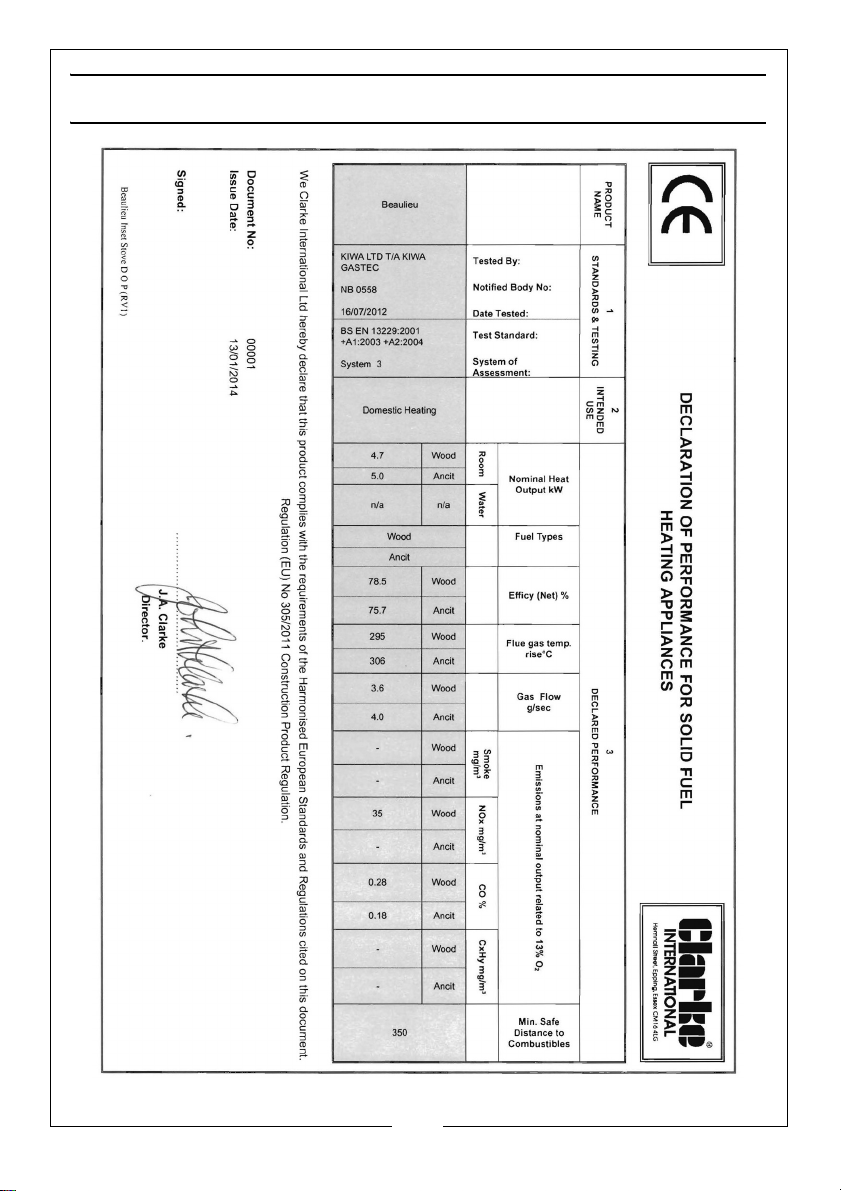
DECLARATION OF CONFORMITY
30
Parts & Service: 020 8988 7400 / E-mail: [email protected] or [email protected]
Page 31

SERVICE HISTORY
1ST SERVICE
Date of Service:..................................................
Next Service Due:...............................................
Signed:...................................................................
Dealer's Stamp/HETAS Registration Number
2ND SERVICE
Date of Service:..................................................
Next Service Due:...............................................
Signed:...................................................................
Dealer's Stamp/HETAS Registration Number
3RD SERVICE
Date of Service:..................................................
Next Service Due:...............................................
Signed:...................................................................
Dealer's Stamp/HETAS Registration Number
4th SERVICE
Date of Service:..................................................
Next Service Due:...............................................
Signed:...................................................................
Dealer's Stamp/HETAS Registration Number
5th SERVICE
Date of Service:..................................................
Next Service Due:...............................................
Signed:...................................................................
Dealer's Stamp/HETAS Registration Number
31
Parts & Service: 020 8988 7400 / E-mail: [email protected] or [email protected]
Page 32
 Loading...