

Page 1
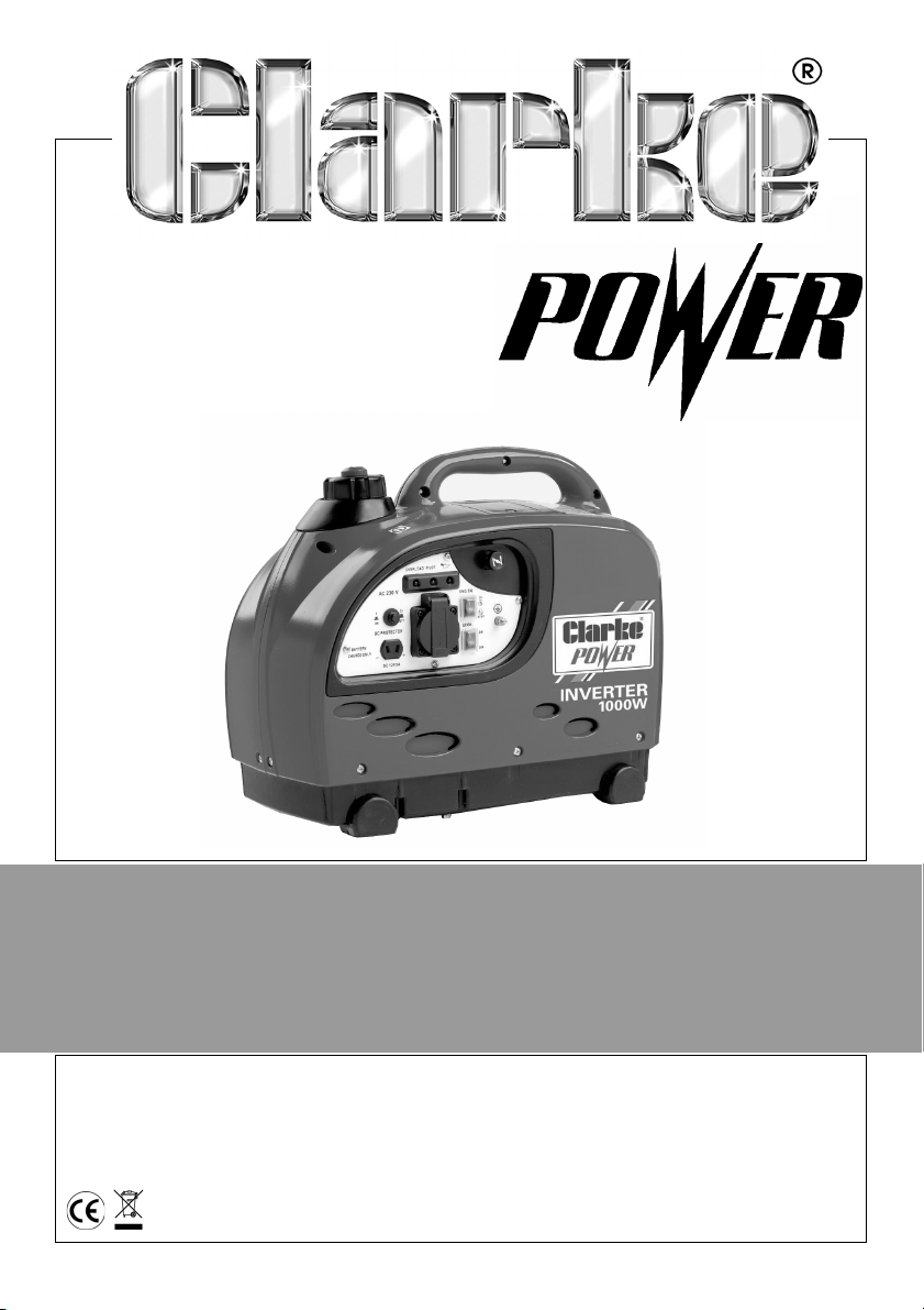
1KW INVERTER GENERATOR
MODEL NO: IG1000
PART NO: 8877050
OPERATION & MAINTENANCE
INSTRUCTIONS
LS0614
Page 2
INTRODUCTION
Thank you for purchasing this CLARKE 1kw Inverter Generator
Before attempting to use this product, please read this manual thoroughly and
follow the instructions carefully. In doing so you will ensure the safety of yourself
and that of others around you, and you can look forward to your purchase
giving you long and satisfactory service.
GUARANTEE
This product is guaranteed against faulty manufacture for a period of 12
months from the date of purchase. Please keep your receipt which will be
required as proof of purchase.
This guarantee is invalid if the product is found to have been abused or
tampered with in any way, or not used for the purpose for which it was
intended.
Faulty goods should be returned to their place of purchase, no product can
be returned to us without prior permission.
This guarantee does not effect your statutory rights.
ENVIRONMENTAL RECYCLING POLICY
Through purchase of this product, the customer is taking on the
obligation to deal with the WEEE in accordance with the WEEE
regulations in relation to the treatment, recycling & recovery and
environmentally sound disposal of the WEEE.
In effect, this means that this product must not be disposed of with general
household waste. It must be disposed of according to the laws governing
Waste Electrical and Electronic Equipment (WEEE) at a recognised disposal
facility.
2
Page 3

TABLE OF CONTENTS
INTRODUCTION ......................................................................... 2
GUARANTEE ............................................................................... 2
ENVIRONMENTAL RECYCLING POLICY .................................... 2
TABLE OF CONTENTS ................................................................. 3
GENERAL SAFETY RULES ............................................................ 4
Work area ........................................................................................ 4
Positioning the generator .............................................................. 4
Fire prevention ................................................................................ 4
Prevention of electric shock .......................................................... 5
Additional safety rules for generators .......................................... 5
SAFETY SYMBOLS ....................................................................... 6
GENERATOR OVERVIEW ............................................................ 7
UNPACKING AND ASSEMBLY ................................................... 8
BEFORE USING THE GENERATOR .............................................. 8
Earth point ....................................................................................... 8
engine oil level ................................................................................ 9
Checking the fuel level .................................................................. 10
Checking the air filter ..................................................................... 11
USING YOUR GENERATOR ........................................................ 12
Starting the engine ......................................................................... 12
Connecting electrical devices ..................................................... 14
Economy switch ............................................................................. 16
Indicator lights ................................................................................. 16
Shutting down the generator ........................................................ 17
MAINTENANCE .......................................................................... 18
The engine oil (every 20 hours of use) .......................................... 18
The air filter (every 50 hours of use) ............................................... 19
The spark plugs (every 50 hours of use) ........................................ 20
Fuel tank filter .................................................................................. 21
PARTS AND SERVICING ............................................................. 21
TROUBLESHOOTING .................................................................. 22
PARTS AND SERVICING ............................................................. 22
SPECIFICATIONS ........................................................................ 23
EXPLODED DIAGRAM & PARTS LIST .......................................... 24
DECLARATION OF CONFORMITY ............................................. 26
DECLARATION OF CONFORMITY ............................................. 27
3
Page 4
GENERAL SAFETY RULES
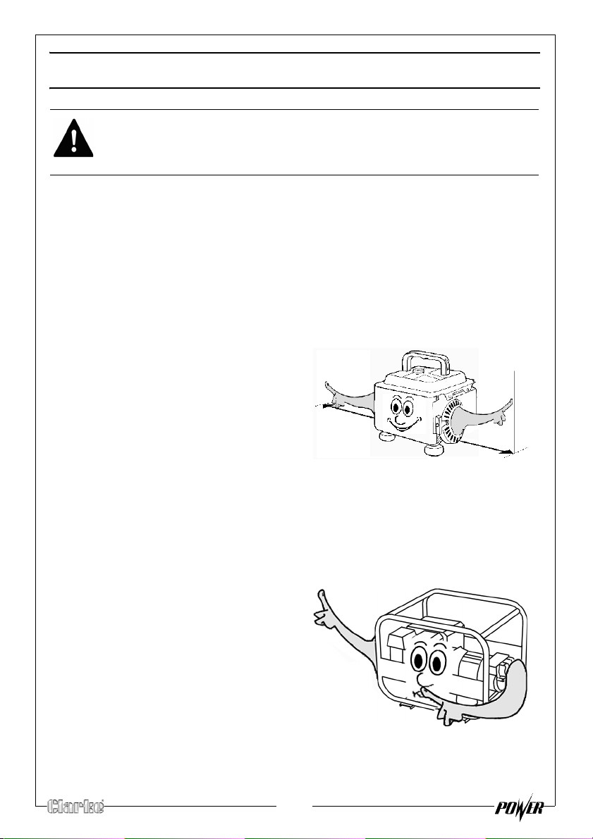
1M (3ft)
1M (3ft)
WARNING: EXHAUST FUMES CAN BE EXTREMELY DANGEROUS IF INHALED
WORK AREA
• Always use in a well ventilated area.
• Always position the exhaust outlet away from people.
• Read these safety instructions before using the equipment.
• Keep children away from the generator
POSITIONING THE GENERATOR
1.
Keep the generator at least 1 m (3
ft) from buildings or other
quipment, or the engine may
e
overheat.
2. Always e
a solid, flat surface.
3. Always ensure the surrounding
area is free from any material that
could burn or be damaged by
heat.
4. Never move or tilt the generator whilst it is switched on.
nsure the generator is on
FIRE PREVENTION
1. Always switch the engine OFF
when refuelling.
2. Always refuel in a well ventilated
area.
3. Never
the vicinity of an open flame.
4. Never over
level specified (See “Checking
the fuel level” on page 10.).
5. Never smoke whilst refuelling and avoid smoking or using a naked flame
near the generator.
refuel while smoking or in
fill the tank, fill to the
4
Page 5
6. Never start the engine if there is spilled fuel. Any spillage must be wiped
clean and the generator allowed to dry before attempting to start the
engine.
PREVENTION OF ELECTRIC SHOCK
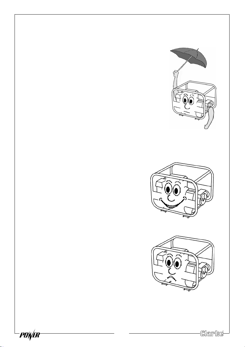
1. Never use the generator in wet
conditions unless it is well protected/
covered. Under these conditions,
adequate ventilation MUST be provided
2. Never operate the generator with wet
hands
3. Never use water or any other liquids to
clean the generator.
4. Make sure you ground (earth) the
generat
or.
ADDITIONAL SAFETY RULES FOR GENERATORS
1. Always ensure the applied load does
not exceed the generator rating.
Overloading t
dangerous and could cause serious
damage.
2.
Always
carrying out any maintenance.
3. Always ensure the generator reaches
operating speed before connecting a
load.
4. Never allow the generator to run out of
fuel when a load is connected.
5. Never tran
in the tank.
6. Do Not
residential power supply; e.g. ring main.
7. Never allow the generator air vents to
become blocked.
he generator is
disconnect the generator when
sport the generator with fuel
connect to a commercial or
5
Page 6
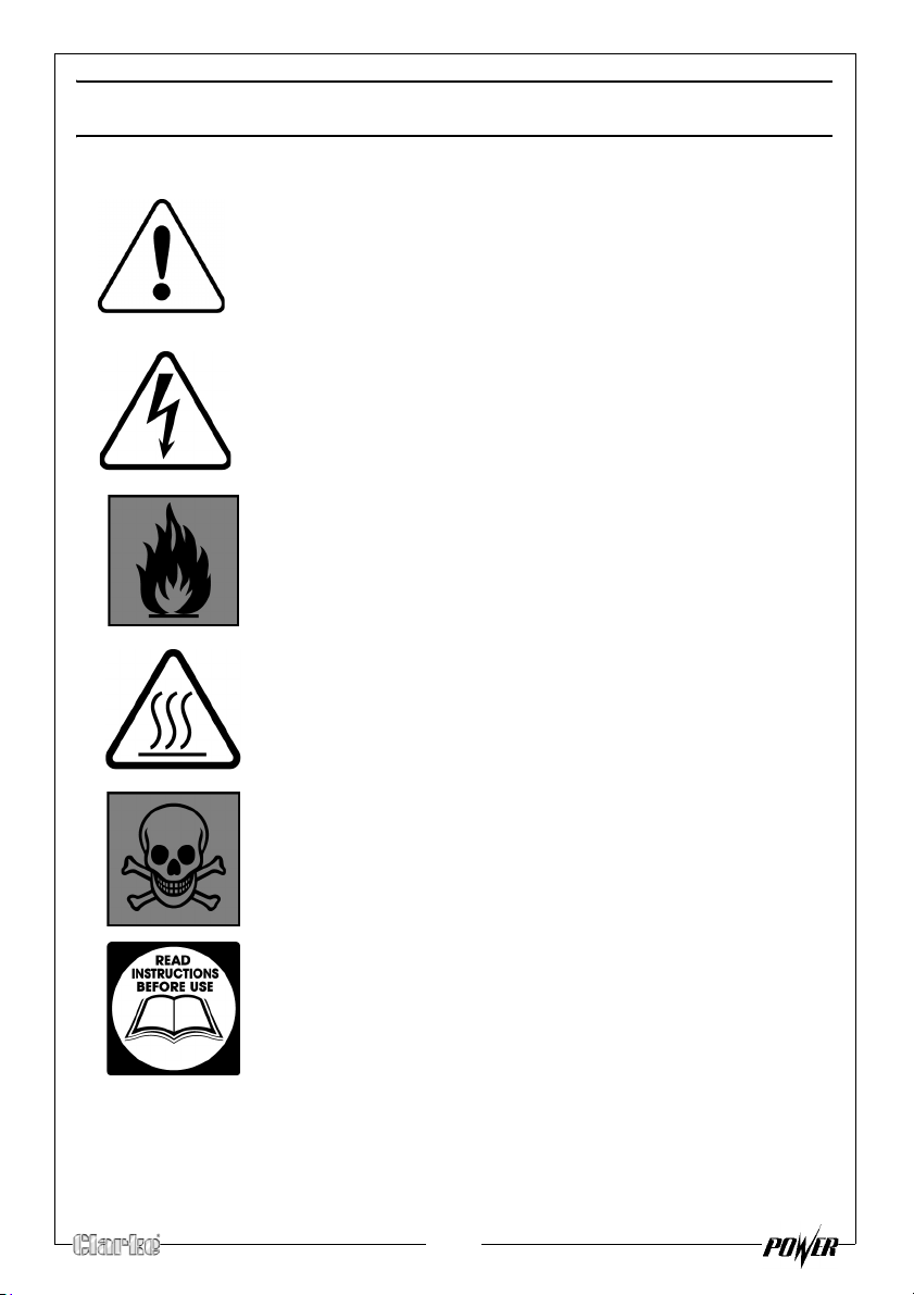
SAFETY SYMBOLS
Caution - The user should be aware of a general hazard
Dangerous Voltage
Flammable
Hot Surface - Do not touch
Poisonous fumes - Do not use the generator in an
enclosed space.
Read Instruction manual before use.
6
Page 7
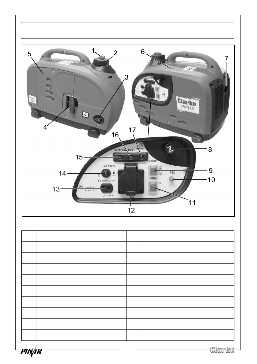
GENERATOR OVERVIEW
NO DESCRIPTION NO DESCRIPTION
1 Air Vent Knob 10 Earthing Point
2 Fuel Cap 11 Economy Control Switch
3 Fuel Valve Knob 12 AC Socket
4 Starting Handle 13 DC Socket
5 Left Side Maintenance Cover 14 DC Circuit Breaker
6 Top Maintenance Cover 15 Overload Indicator
7 Muffler 16 Output Indicator
8 Choke 17 Oil Alarm Indicator
9 Engine ON/OFF Switch
7
Page 8
UNPACKING AND ASSEMBLY
Unpack your Generator and check to ensure the following items are present.
Should there be any deficiency or damage caused during transit contact
your Clarke dealer immediately.
• 1 x Inverter Generator
• 1 x Spark Plug Box Spanner
• 1 x Screwdriver/Tommy Bar
• 1 x Container with Spout for Oil Filling
• 1 x Operating & Instruction Manual
• 1 x 12V Battery Connector Lead
• 1 x Oil Drain Tube
BEFORE USING THE GENERATOR
IMPORTANT: Generators should ALWAYS be earthed. Make sure you ground
(earth) the generator.
ore using your generator check that:
Bef
• The generator is in good condition and free from any damage.
• The generator is clean and free from fuel or oil spillage.
• The generator is correctly located for use (See page 4).
• The fuel system and connectors are intact and there is no leakage.
NOTE: Always use a funnel to fill the fuel tank so as to avoid accidental
spillage of fuel. If fuel is spilled it must be removed from the unit
before attempting to start the engine.
WARNING: ENSURE THERE IS ADEQUATE FUEL IN THE TANK WHEN USING
THE GENERATOR. RUNNING OUT OF FUEL OR STOPPING THE ENGINE
SUDDENLY WITH A LOAD CONNECTED COULD CAUSE SERIOUS DAMAGE.
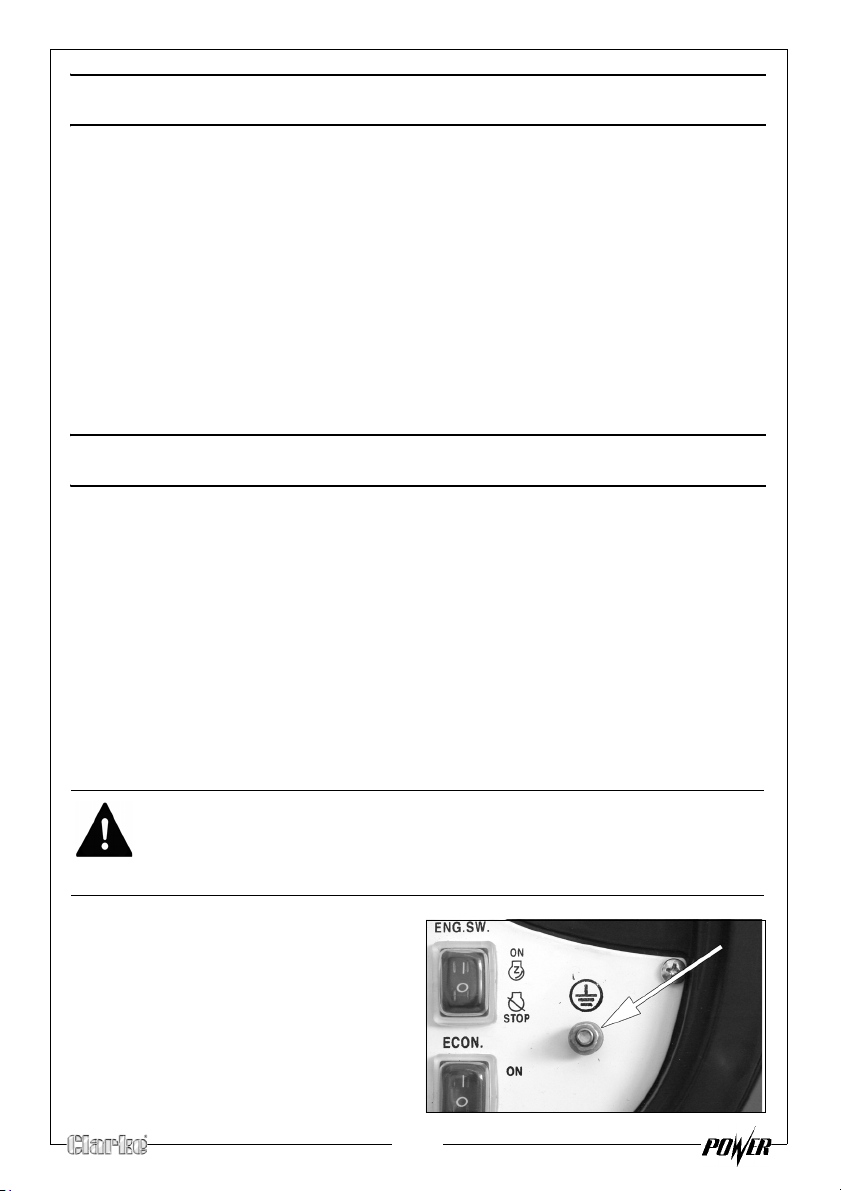
EARTH POINT
Always connect the generator to an
earth point. The earth terminal is
shown on the right.
8
Page 9
ENGINE OIL LEVEL
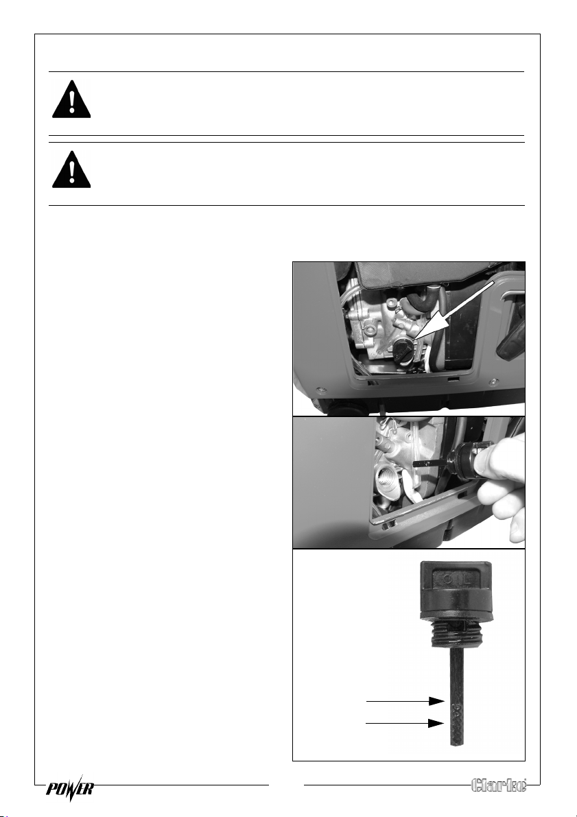
Max Level
Min. Level
WARNING: THE GENERATOR IS SUPPLIED WITHOUT ANY OIL, OIL MUST BE
ADDED AS FOLLOWS BEFORE USING THE GENERATOR.
WARNING: TAKE CARE NOT TO TOUCH ANY HOT PARTS OF THE
GENERATOR WHEN CHECKING THE LEVEL OR ADDING THE OIL.
1. Make sure the generator is on a level surface and switched off.
2. Remove the left side
3.
Turn the oil filler cap anticlockwise and remove from the oil
reservoir, wipe the dipstick with a
clean cloth.
4. Insert the dipstick back into the oil
filler tube and then remove it
again. Do not screw in the oil filler
cap/dipstick when doing this.
maintenance panel.
5.
If the oil is below the Min. level on
the dipstick, add oil to the oil
reservoir
• Oil Capacity (See
• We recommend the use of
• Do not tilt the generator when
6. Replace the oil filler cap.
.
“Speci
fications” on page 23)
SAE30 oil in this generator.
adding engine oil. This could
result in overfilling and damage
to the engine.
9
Page 10
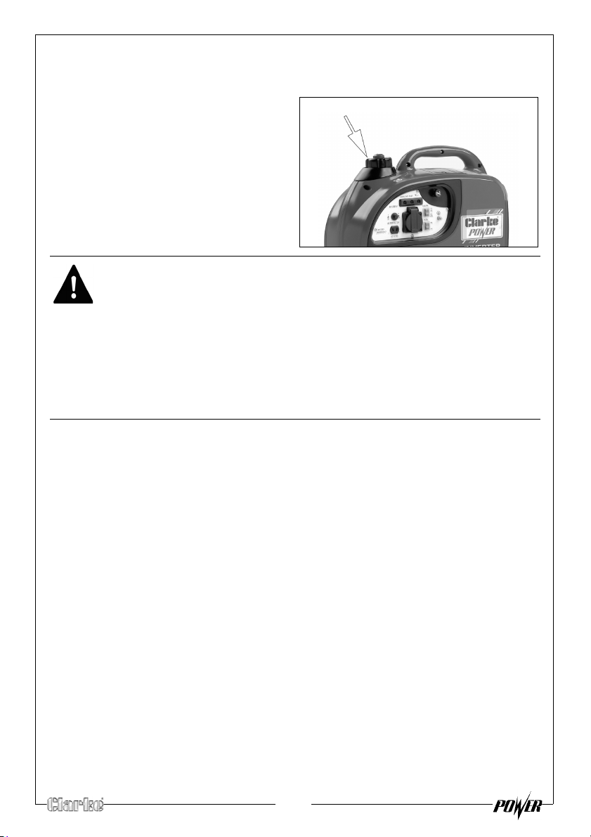
CHECKING THE FUEL LEVEL
Fuel filler cap
Make sure there is sufficient fuel in the tank.
1.
To check the fuel level, open the
fuel filler cap.
2. Slowly add fuel to the fuel tank
(maximum 2.7L
• Do not overfill the fuel tank.
3. Replace the fuel filler cap
secur
ely.
WARNING: FUEL IS HIGHLY FLAMMABLE AND POISONOUS.
WARNING: SEE “GENERAL SAFETY RULES” ON PAGE 4 AND READ THEM
CAREFULLY BEFORE REFUELING.
WARNING: DO NOT FILL ABOVE THE TOP OF THE FUEL FILTER OR IT MAY
OVERFLOW WHEN THE FUEL HEATS UP AND EXPANDS.
WARNING: WIPE UP ANY SPILLED FUEL IMMEDIATELY.
WARNING: AFTER REFUELING, MAKE SURE THE TANK CAP IS TIGHTENED
SECURELY.
RECOMMENDED FUEL
Your generator has been designed to use regular unleaded gasoline with a
octane number of 86 or higher.
)
10
Page 11
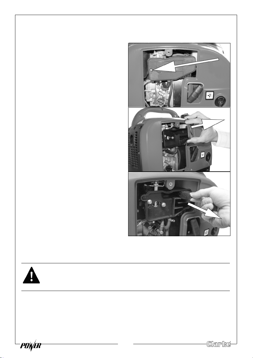
CHECKING THE AIR FILTER
1. Remove the left side maintenance panel.
2.
Remove the air filter cover screw
shown on the right.
Remove the air filter cover.
3.
Remove the air filter element.
4.
5. Make sure that the air filter is
clean and not
• If the air filter is damaged
co
ntact Clarke spare parts
department for a replacement
See page 22
• If the filter is dirty, wash the filter
in a solution of warm water and
mild detergent and rinse thoroughly. Leave the filter to dry
completely, once it is dry immerse the filter in clean engine oil and
squeeze the filter to remove excess oil.
damaged.
WARNING: DO NOT USE INFLAMMABLE SOLVENTS OR PETROL TO CLEAN
THE AIR FILTER.
6. Replace the filter back into its original position an
cover.
11
d replace the air filter
Page 12
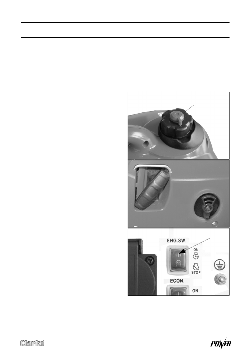
USING YOUR GENERATOR
air vent knob
STARTING THE ENGINE
• Check that the is sufficient fuel in the fuel tank, See page 10.
• Check that the is sufficient oil in the generator, See page 9.
1. Remove all connections from the AC sockets.
2.
Hold the fuel tank cap so that it
will not move, and turn the air
vent knob to the ON position.
3. Turn fuel valve to the ON position.
4. Set the engine switch to ‘ON’.
12
Page 13
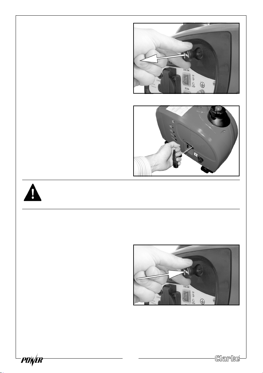
5. Set the choke to the required
position.
• If the engine is cold, pull the
ch
oke all the way out.
• If the generator is warm, push
the choke all the way in.
NOTE: In some circumstances the
choke may still need to be
pulled out even though the
engine is warm.
6.
Hold the generator handle firmly
and pull the starting handle lightly
l you start to feel resistance
unti
and then pull up sharply to start
the engine.
NOTE: You may have to do this
more than once.
.
WARNING: ONCE THE GENERATOR HAS STARTED, RELEASE THE STARTING
HANDLE SLOWLY TO AVOID INJURY/DAMAGE AS IT WHIPS BACK.
NOTE: When you first start the generator, the overload indicator may light
up for a few seconds, this is normal. If the overload indicator is still
lit after 5 seconds, stop the engine and contact your Clarke
dealer.
Once the engine has warmed up,
7.
push the choke knob all the way
in.
13
Page 14
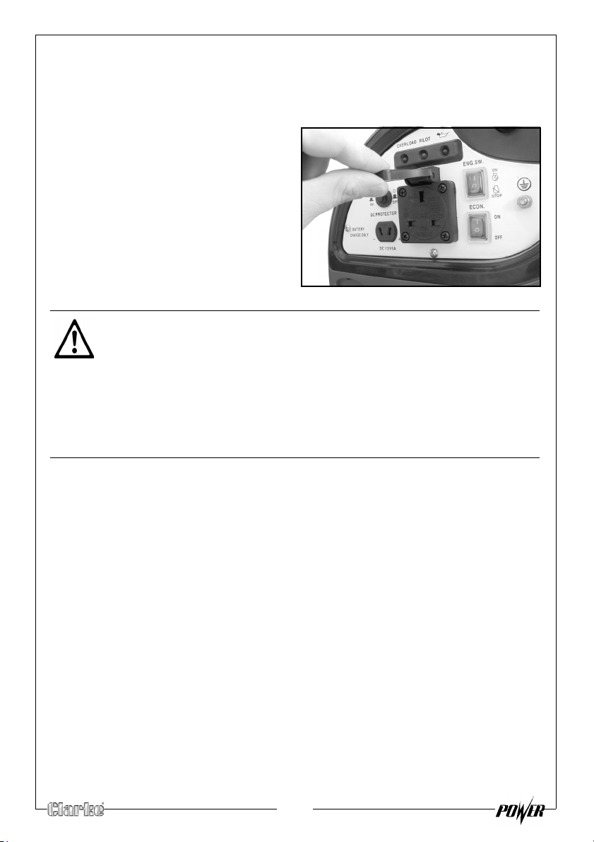
CONNECTING ELECTRICAL DEVICES
The generator can supply both 230V AC and 12V DC
AC POWER
Start the engine. See page 12.
1.
2. Make sure the appliance is turned
off be
fore connecting it to the
generator.
3. Connect the appliance to the
generator.
CAUTION: MAKE SURE THAT THE APPLIANCE BEING CONNECTED IS IN
GOOD WORKING ORDER, IF IT BEGINS TO ACT ABNORMALLY OR STOPS
SUDDENLY, DISCONNECT IT FROM THE GENERATOR
CAUTION: MAKE SURE THE APPLIANCE DOES NOT EXCEED THE MAXIMUM
RATED LOAD FOR THE GENERATOR.
CAUTION: ANY DEVICE THAT CONTAINS AN INDUCTIVE LOAD E.G.
DEVICES THAT CONTAIN A MOTOR MAY REQUIRED MORE CURRENT ON
STARTUP.
14
Page 15
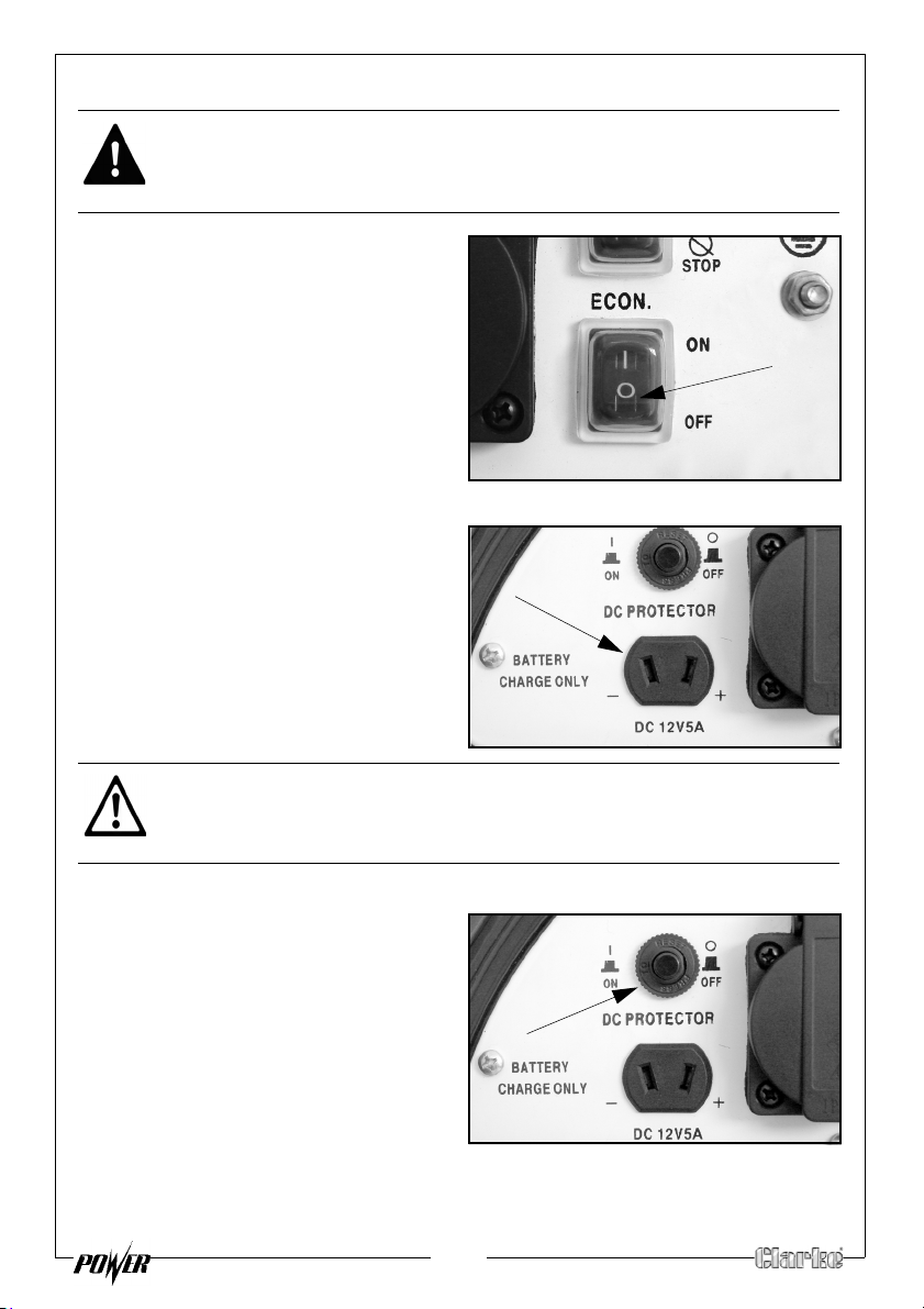
DC POWER (FOR CHARGING CAR BATTERIES ONLY)
WARNING: FOR YOUR SAFETY PERFORM THE FOLLOWING INSTRUCTIONS
IN THE ORDER SHOWN.
1. Set the economy control switch to
'OFF'.
2. Start the engine. See page 12.
3. Connect the battery charging
leads
to the battery.
• Make sure you clamp the red
wir
e to the positive (+) terminal
and the black wire to the
negative (-) terminal of the
battery.
4. Connect the battery charging
leads to the generator.
• The battery will begin to charge
5. Monitor the voltage across the
b
attery regularly during charging
and disconnect the battery when
the voltage reaches 14.4 volts.
CAUTION: WHEN DISCONNECTING THE BATTERY, ALWAYS DISCONNECT
THE NEGATIVE LEAD FIRST.
DC OVER LOAD PROTECTOR
If the DC overload protector
activates
then press the reset button shown on
the right.
, wait for a few minutes and
15
Page 16
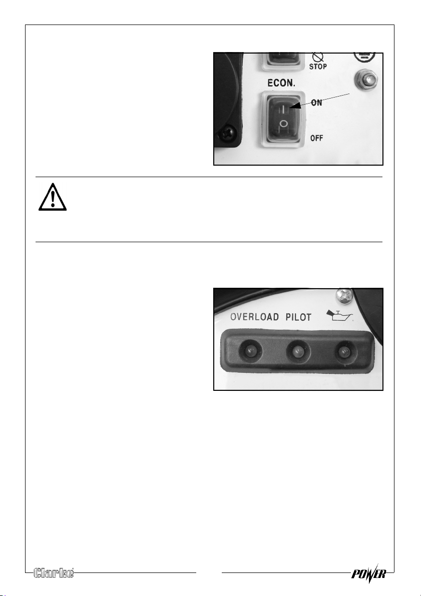
ECONOMY SWITCH
When the economy control switch is
turned on, the engine speed varies
according to the load connected.
This results in decreased fuel
consumption and less noise.
When the economy control switch is
turned off, the engine runs at the
5,500 r/min. regardless of whether
there is a load connected or not.
CAUTION: THE ECONOMY CONTROL DOES NOT WORK EFFECTIVELY IF
THE ELECTRICAL APPLIANCE REQUIRES ‘BURSTS’ OF POWER.
CAUTION: TURN THE ECONOMY CONTROL FEATURE OFF WHEN
CONNECTING HIGH LOAD APPLIANCES OR WHEN CONNECTING TO THE
DC OUTPUT.
INDICATOR LIGHTS
PILOT LIGHT
The pilot light (Green) will remain on
during normal operation.
OVERLOAD INDICATOR
The overload indicator (Red) will light
up if there is an overload (in excess of
1kva) or a short circuit in the
connected appliance.
If this happens:
1. Turn off any connected electrical devices and stop the engine.
2. Reduce the total wattage of connected electric devices within the
application range.
3. Check air inlet and around the control unit. If any blockages are found,
remove them.
4. After checking, restart the engine.
LOW OIL INDICATOR
The oil indicator will light up when the oil level is low. See page 9.
16
Page 17
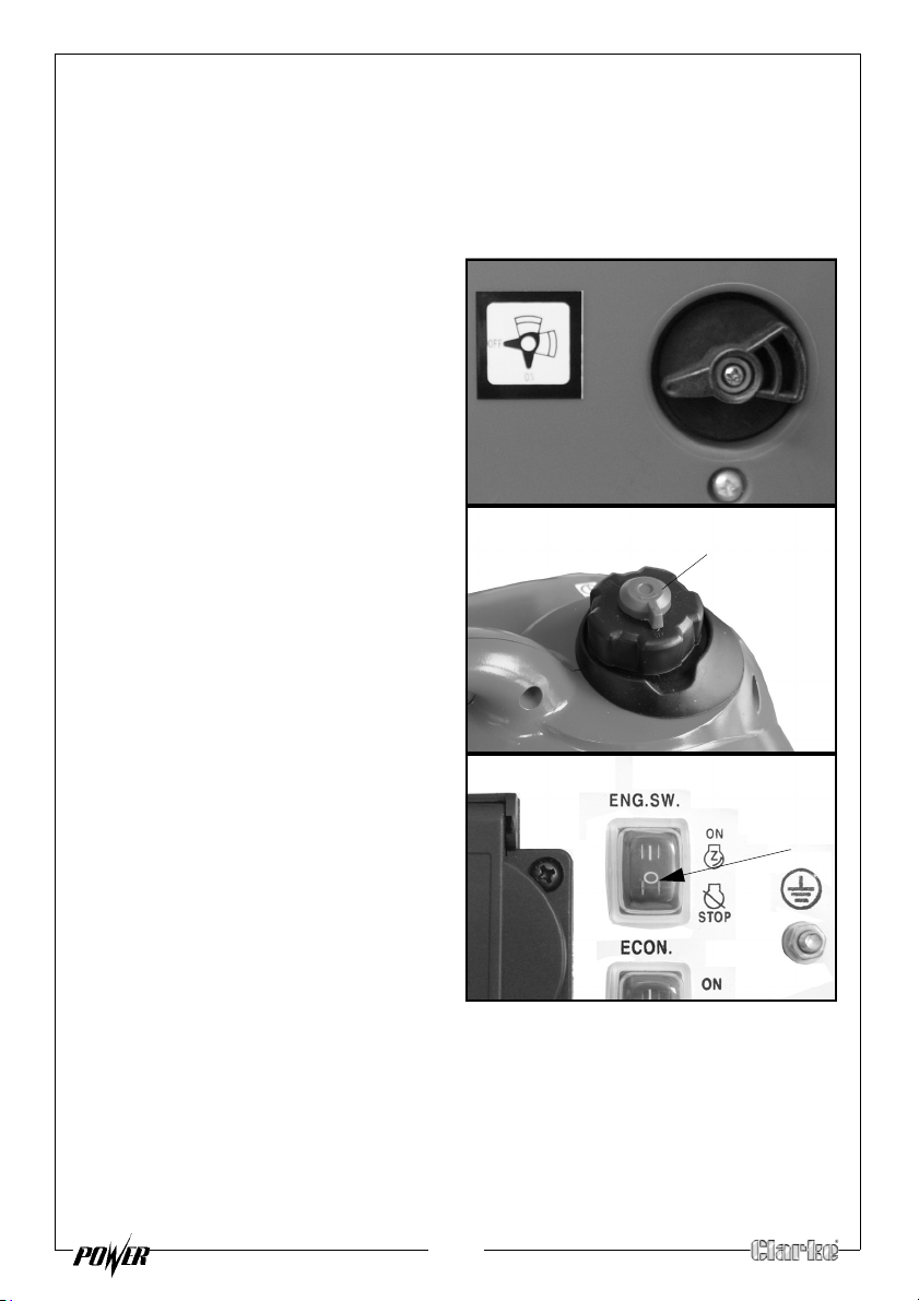
SHUTTING DOWN THE GENERATOR
air vent knob
To stop the generator in an emergency simply set the engine switch to ‘OFF’.
NOTE: T
NOTE: Set the economy control switch to the ‘0’ (OFF) position.
1. Disconnect any electric devices.
2.
3.
urn off any electric devices.
Turn the fuel valve knob to “OFF”.
Turn the air vent knob to the off
position.
4. Set the engine switch to the “0”
(OFF) position.
17
Page 18
MAINTENANCE
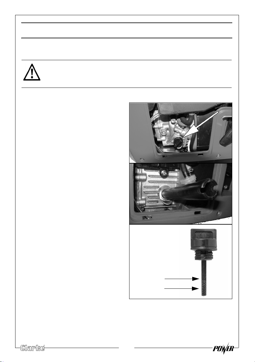
Max Level
Min. Level
THE ENGINE OIL (EVERY 20 HOURS OF USE)
CAUTION: PROLONGED EXPOSURE TO USED ENGINE OIL IS DANGEROUS,
ALWAYS WASH YOUR HANDS THOROUGHLY AFTER HANDLING USED
ENGINE OIL.
1. Remove the left side maintenance panel.
2.
Turn the oil filler cap anticlockwise and remove from the oil
tank, w
clean cloth.
3.
Screw the oil drain tube into the oil
tank as shown and lift the
genera
the oil tank into a suitable
container.
ipe the dipstick with a
tor and pour the oil out of
4.
5. Replace the oil filler cap and
ENVIRONMENTAL PROTECTION
One of the most damaging sources of pollution is oil. Do not throw away used
engine oil in with your domestic trash or down drains and sinks. Place it in a
leak proof container and dispose of it according to local regulations.
Fill the oil reservoir to the Max level
with fresh oil.
• Oil Capacity (See
“Specifications” on page 23.)
• We recommend the use of
SAE30 oil in this generator.
m
aintenance panel.
18
Page 19
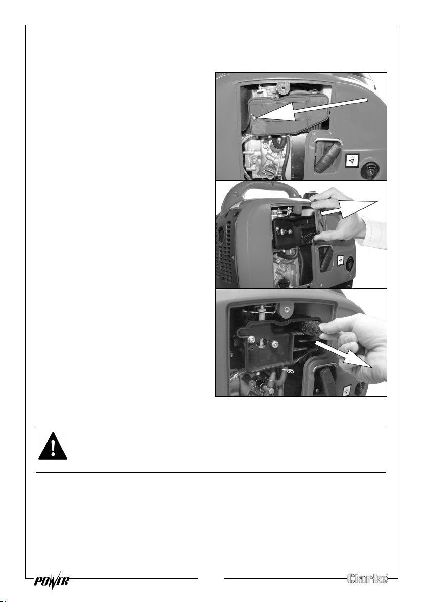
THE AIR FILTER (EVERY 50 HOURS OF USE)
1. Remove the left side maintenance panel.
2.
Remove the air filter cover screw
shown on the right.
Remove the air filter cover.
3.
Remove the air filter element.
4.
5. If the air filter is damaged contact
Clark
e spare parts department for
a replacement See page 22.
• If the filter is dirty, wash the filter
in a solution of warm water and
mild detergent and rinse
thoroughly. Leave the filter to
dry completely, once it is dry
immerse the filter in clean
engine oil and sqeeze the filter to remove excess oil.
WARNING: DO NOT USE FLAMMABLE SOLVENTS OR PETROL TO CLEAN THE
AIR FILTER.
6. Replace the filter back into its original position an
cover.
19
d replace the air filter
Page 20
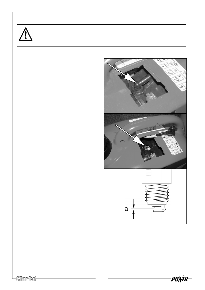
THE SPARK PLUGS (EVERY 50 HOURS OF USE)
CAUTION: ALLOW THE ENGINE TO COOL BEFORE REMOVING THE SPARK
PLUG.
1. Remove the top maintenance panel.
2.
Remove the spark plug cap from
the spark plug.
3. Use a spark plug spanner
(supplied) to remove the spark
plug.
4. Check for discoloration and
remove any
carbon build up.
Check the spark plug gap (a), it
5.
should be between 0.6 and 0.7
mm, adjust if necessary.
6. Check the overall condition of the
sp
ark plug and replace if
damaged.
7. Reinstall the spark plug and
replace the spark plug cap.
20
Page 21
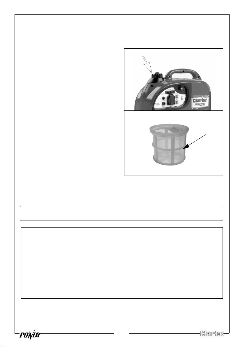
FUEL TANK FILTER
Fuel filler cap
Fuel filter
For Parts & Servicing, please contact your nearest dealer, or
CLARKE International, on one of the following numbers.
PARTS & SERVICE TEL: 020 8988 7400
PARTS & SERVICE FAX: 020 8558 3622
or e-mail as follows:
PARTS: [email protected]
SERVICE: [email protected]
Just inside the fuel tank is a fuel filter, check this filter periodically and remove
any contaminants which may have accumulated.
1.
Remove the fuel tank cap and
filter.
2.
Clean the filter with solvent. If
damaged, replace.
3. Wipe the filter and insert it.
4. Make sure the tank cap is
tightened secur
ely.
PARTS AND SERVICING
21
Page 22
TROUBLESHOOTING
For Parts & Servicing, please contact your nearest dealer, or
CLARKE International, on one of the following numbers.
PARTS & SERVICE TEL: 020 8988 7400
PARTS & SERVICE FAX: 020 8558 3622
or e-mail as follows:
PARTS: [email protected]
SERVICE: [email protected]
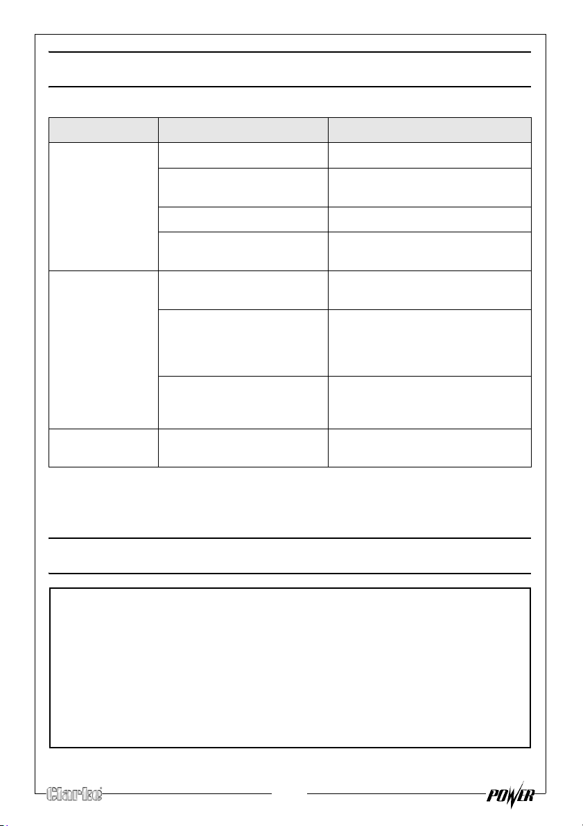
PROBLEM CAUSE SOLUTION
The generator fails
o start
t
The generator fails
generate
to
electricity
The generator is
ifficult to start
d
Engine switch is off Set the engine switch to ‘on’
Not enough oil in the
nerator
ge
No fuel Add more fuel, See page 10
Spark plugs not working
correctly
The device you are trying to
power is faulty
The overload indi
(dc supply only) The DC
erload protector has
Ov
activated.
The air filter is dirty Clean the air filter. See page 19
cator is on Remove the appliance
Add more oil, See page 9
Change the spark plugs, See
page 20
Make sure the device you want to
power is working properly
immediately, do not connect any
appliance that requires more than
1 KVA.
Press the reset button. See page 15
If this does not solve your problem, please contact the Clarke service
department. see below.
PARTS AND SERVICING
22
Page 23
SPECIFICATIONS
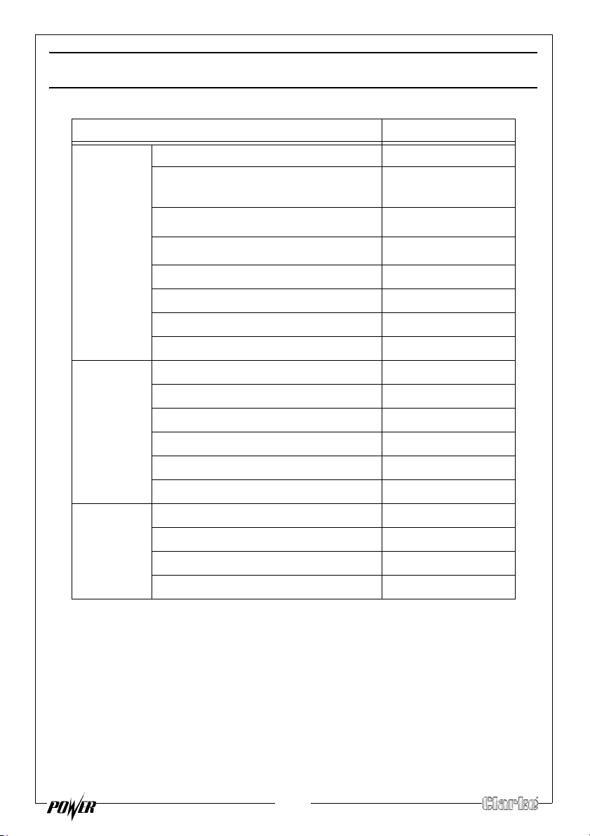
Engine Engine Model 144F
Type
Forced air cooled 4stroke gasoline OHV
IG1000
Displacement (cm3)
Ignition type
Fuel tank capacity (L) 2.7
Maximum run time (h) 6
Engine oil capacity (L) 0.25
Guaranteed sound power (L
Generator Rated Frequency (Hz) 50
Rated AC Voltage (V) 230
Rated Power (kVA) 0.9
Max. Power (kVA) 1
Rated DC Voltage (V) 12
Rated DC Current (A) 5
Dimensions Length (mm) 460
Width (mm) 250
Height (mm) 420
Unpacked Weight (kg) 15
WA dB) 92
53
TDI
23
Page 24
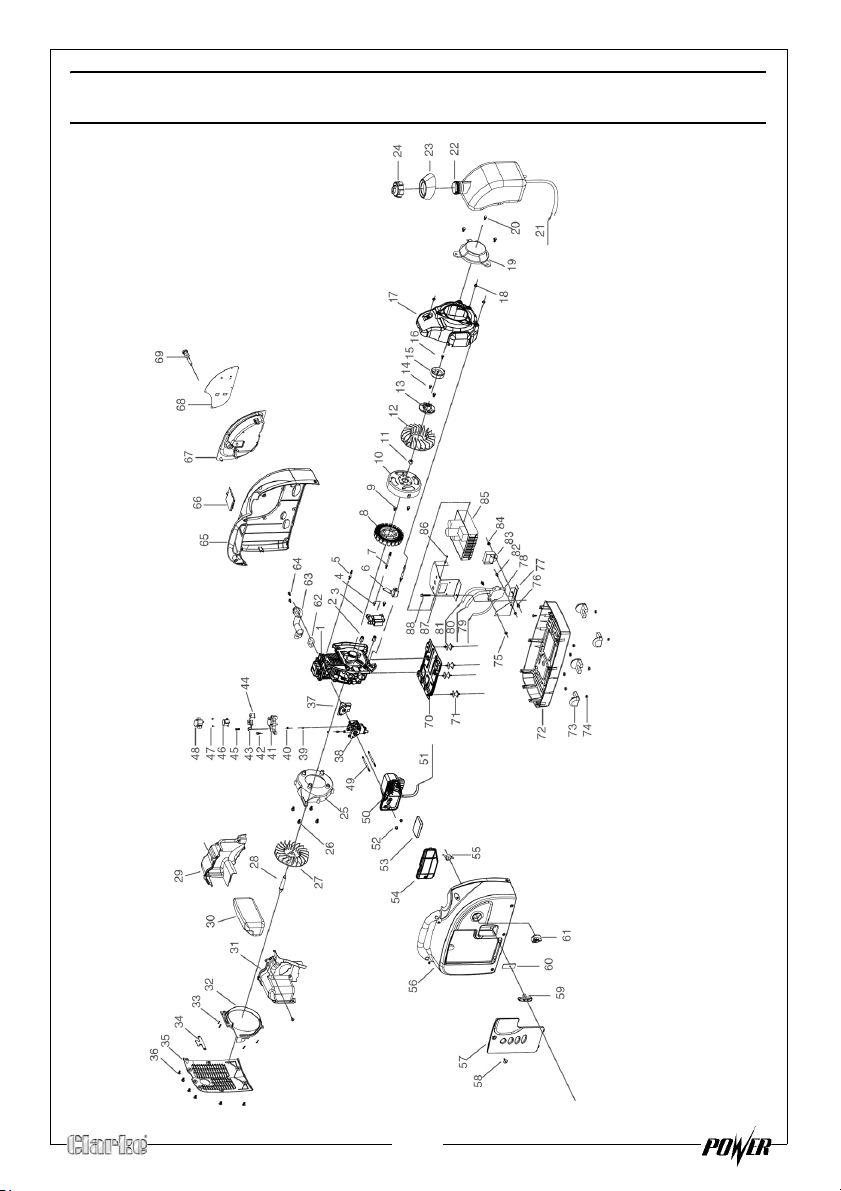
EXPLODED DIAGRAM & PARTS LIST
24
Page 25
EXPLODED DIAGRAM & PARTS LIST
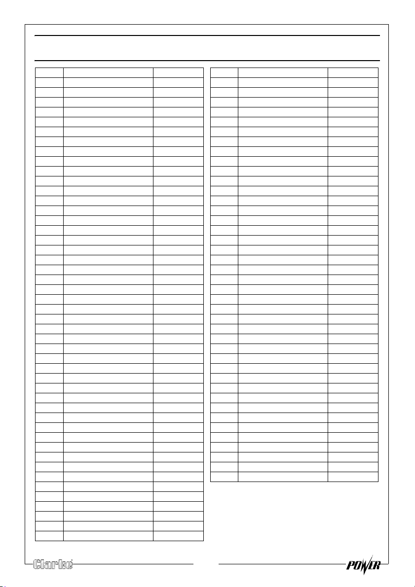
NO DESCRIPTION PAR T NO
1 Engine RKIG100001
2 Ignition coil sleeve RKIG100002
3 Ignition coil RKIG100003
4 M6 Hex bolt RKIG100004
5 Stud(short) RKIG100005
6 Sensor Assembly RKIG100006
7 Stud (long) RKIG100007
8 Stator assembly RKIG100008
9 M6 Hex bolt RKIG100009
10 Rotor assembly RKIG100010
11 M10 nut RKIG100011
12 Fan blade RKIG100012
13 Clutch RKIG100013
14 M6 nut RKIG100014
15 Clutch pedal RKIG100015
16 M6 Hex bolt RKIG100016
17 Fan blade cover RKIG100017
18 M5 nut RKIG100018
19 Recoil Starter RKIG100019
20 M6 Hex bolt RKIG100020
21 Fuel outlet hose RKIG100021
22 Fuel tank RKIG100022
23 Fuel tank cover RKIG100023
24 Fuel cap RKIG100024
25 Front clapboard RKIG100025
26 M5 hex bolt RKIG100026
27 Fan RKIG100027
28 Fan blade shaft RKIG100028
29 Left fan cover RKIG100029
30 Muffler assy RKIG100030
31 Right fan cover RKIG100031
32 Fan cover RKIG100032
33 M4 tapping screw RKIG100033
34 Handle holder RKIG100034
35 Rear cover RKIG100035
36 M6 Hex bolt RKIG100036
37 Bakelite pad RKIG100037
38 Carburetor RKIG100038
39 M4 nut RKIG100039
40 Washer RKIG100040
41 Step motor holder RKIG100041
42 M4 hex bolt RKIG100042
43 Choke holder (1) RKIG100043
44 Choke holder (2)
45 M4 hex bolt RKIG100045
46 Step motor RKIG100046
47 M3 hex bolt RKIG100047
RKIG100044
NO DESCRIPTION PART NO
48 Step motor top cover RKIG100048
49 Double-headed stud RKIG100049
50 Air filter RKIG100050
51 Breath pipe RKIG100051
52 M5 nut RKIG100052
53 Air filter sponge RKIG100053
54 Air filter cover RKIG100054
55 Fuel cock RKIG100055
56 Left case RKIG100056
57 Left maintenance cover RKIG100057
58 M6 screw RKIG100058
59 Starter grip RKIG100059
60 Starter cover RKIG100060
61 Fuel cock, plastic knob RKIG100061
62 Vent-pipe washer RKIG100062
63 Ve nt -p ip e RKIG100063
64 M5 nut RKIG100064
65 Right case RKIG100065
66 Top maint en an ce cover RKIG100066
67 Controller box RKIG100067
68 Controller panel RKIG100068
69 Choke soft axis RKIG100069
70 Engine holder RKIG100070
71 Absorber RKIG100071
72 Bottom bracket RKIG100072
73 Pads RKIG100073
74 M5 nut RKIG100074
75 M5 screw cap RKIG100075
76 M5 Hex bolt RKIG100076
77 CDI box holder RKIG100077
78 Vacuum pu mp RKIG100078
79 Fuel inlet hose RKIG100079
80 Vacuum pipe RKIG100080
81 Pump inlet hose RKIG100081
82 M5 Hex bolt RKIG100082
83 CDI box assembly RKIG100083
84 M5 nut RKIG100084
85 Inverter assembly RKIG100085
86 M4 hex bolt RKIG100086
87 Inverter holder RKIG100087
88 M5 Hex bolt RKIG100088
25
Page 26
DECLARATION OF CONFORMITY
DECLARATION OF CONFORMITY
This is an important document and should be retained.
Product Description: 1000W Inverter Generat or
Model number(s): IG1000
Serial / batch Number: N/A
Date of Issue: 20/01/2010
(Noise Conformity)
Notified Body: Societe Nationale De Certification ET D’
Homologation S.A.R.L (SNCH)
11 Rout De Sandweiler
5230 Sandweiler
Luxembourg
Technical Documentation Holder: Alan Pond
Clarke International
2a Shrubland Road
London E10,7RB
UK
Conformity Assessment Procedure: to 2000/14/EC Annex VI
Manufacturer: Clarke International
Noise Related Value: 1.0 kW
Measured Sound Power Level: 88.48 dB
Guaranteed Sound Power Level: 89 dB
IG1000 Generator (rv3).doc Page 1 of 2
26
Page 27
DECLARATION OF CONFORMITY
DECLARATION OF CONFORMITY
This is an important document and should be retained.
We hereby declare that this product(s) complies with the following directive(s):
2004/108/EC Electromagnetic Compa tibility Directive.
2006/42/EC Machinery Directive.
2006/95EC Low Voltage Equipment Directive.
2000/14/EC Noise Emissions Directive (amen ded by 2005/88/EC).
97/68/EC Emission of Gaseous Particulates (amended by 2006/96/EC)
The following standards have been applied to the product(s):
EN 55012:2002+A1, EN 61000- 6-1:2001, EN 61000-6-3: 2001+A11, EN 3744:1995, EN 12601:2001,
EN 60034-22:1997.
The technical documentation required to d emonstrate that the product(s) meet(s) the requirement(s) of the
aforementioned directive(s) has been compiled and is ava ilable for inspection by the relevant enforcement
authorities.
The CE mark was first applied in: 2006
Signed:
IG1000 Generator (rv3).doc Page 2 of 2
27
Page 28

 Loading...