

Page 1
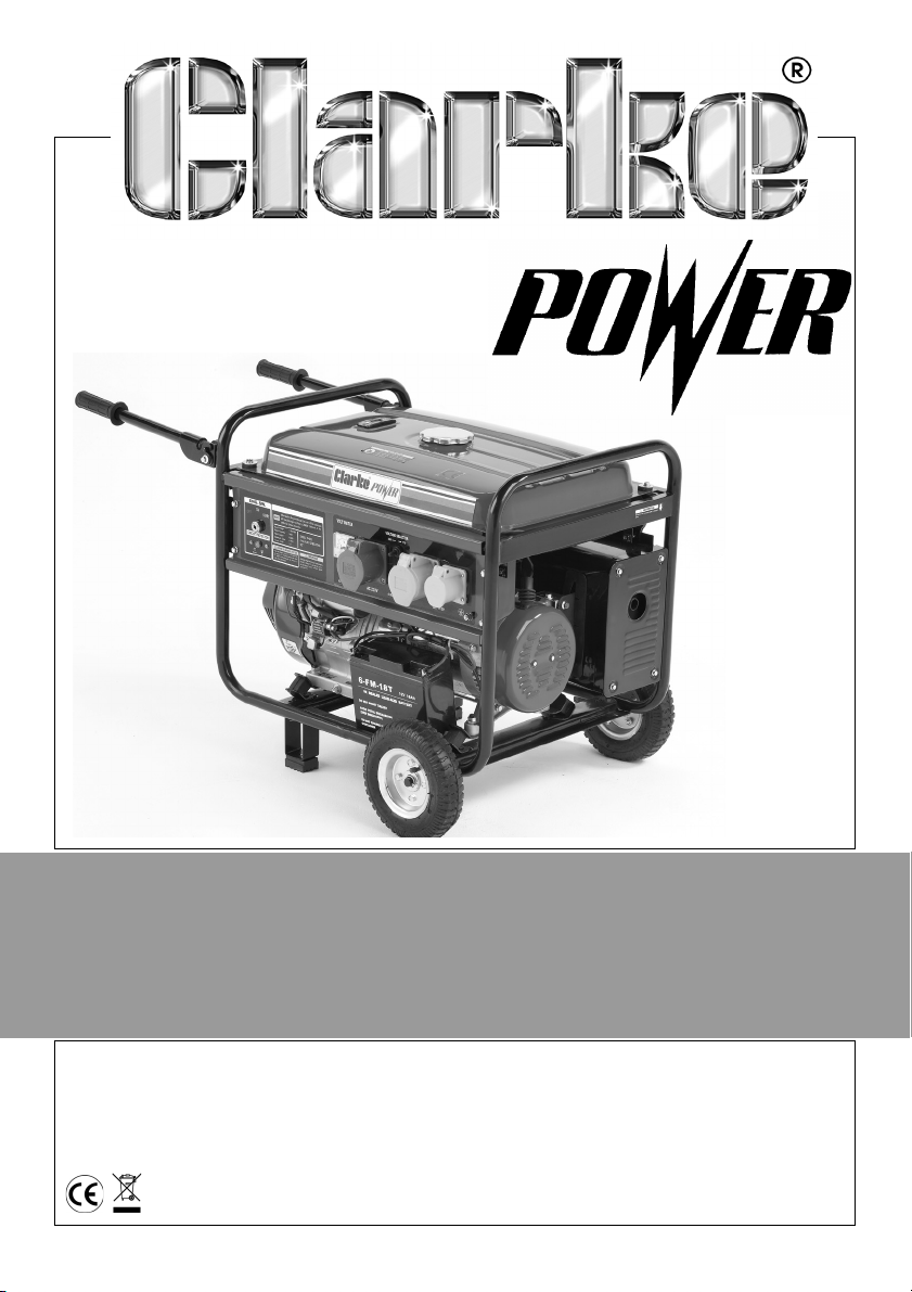
GENERATOR
MODEL NO: FG4050ES / FG5100ES
PART NO: 8857715, 8857720
OPERATION & MAINTENANCE
INSTRUCTIONS
LS0914
Page 2
INTRODUCTION
Thank you for purchasing this CLARKE Generator.
Before attempting to use this product, please read this manual thoroughly and
follow the instructions carefully. In doing so you will ensure the safety of yourself
and that of others around you, and you can look forward to your purchase
giving you long and satisfactory service.
GUARANTEE
This product is guaranteed against faulty manufacture for a period of 12
months from the date of purchase. Please keep your receipt which will be
required as proof of purchase.
This guarantee is invalid if the product is found to have been abused or
tampered with in any way, or not used for the purpose for which it was
intended.
Faulty goods should be returned to their place of purchase, no product can
be returned to us without prior permission.
This guarantee does not effect your statutory rights.
ENVIRONMENTAL RECYCLING POLICY
Through purchase of this product, the customer is taking on the
obligation to deal with the WEEE in accordance with the WEEE
regulations in relation to the treatment, recycling & recovery and
environmentally sound disposal of the WEEE.
In effect, this means that this product must not be disposed of with general
household waste. It must be disposed of according to the laws governing
Waste Electrical and Electronic Equipment (WEEE) at a recognised disposal
facility.
2
Page 3
GENERAL SAFETY RULES
1M (3ft)
1M (3ft)
WARNING: EXHAUST FUMES CAN BE EXTREMELY DANGEROUS IF INHALED
WORK AREA
• Always use in a well ventilated area.
• Always position the exhaust outlet away from people.
• Never use indoors or in a confined space.
• Read these safety instructions before using the equipment.
• Keep children away from the generator
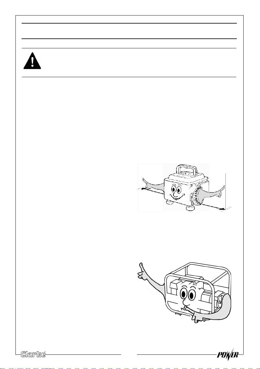
POSITIONING THE GENERATOR
1.
Always leave a least a 1M gap
between the generator and any
rounding building or structures.
sur
2. Always e
a solid, flat surface.
3. Always en
area is free from any material that
could burn or be damaged by
heat.
4. Never move or tilt the generator whilst it is switched on.
nsure the generator is on
sure the surrounding
FIRE PREVENTION
1. Always switch the engine OFF
when refuelling.
2. Always
source of heat.
3. Always refuel in a well ventilated
area.
4. Never over
level specified (See “Checking
the fuel level” on page 12.).
5. Never smoke whilst refuelling and avoid smoking or using a naked flame
near the generator.
refuel away from any
fill the tank, fill to the
3
Page 4
6. Never start the engine if there is spilled fuel. Any spillage must be wiped
clean and the generator allowed to dry before attempting to start the
engine.
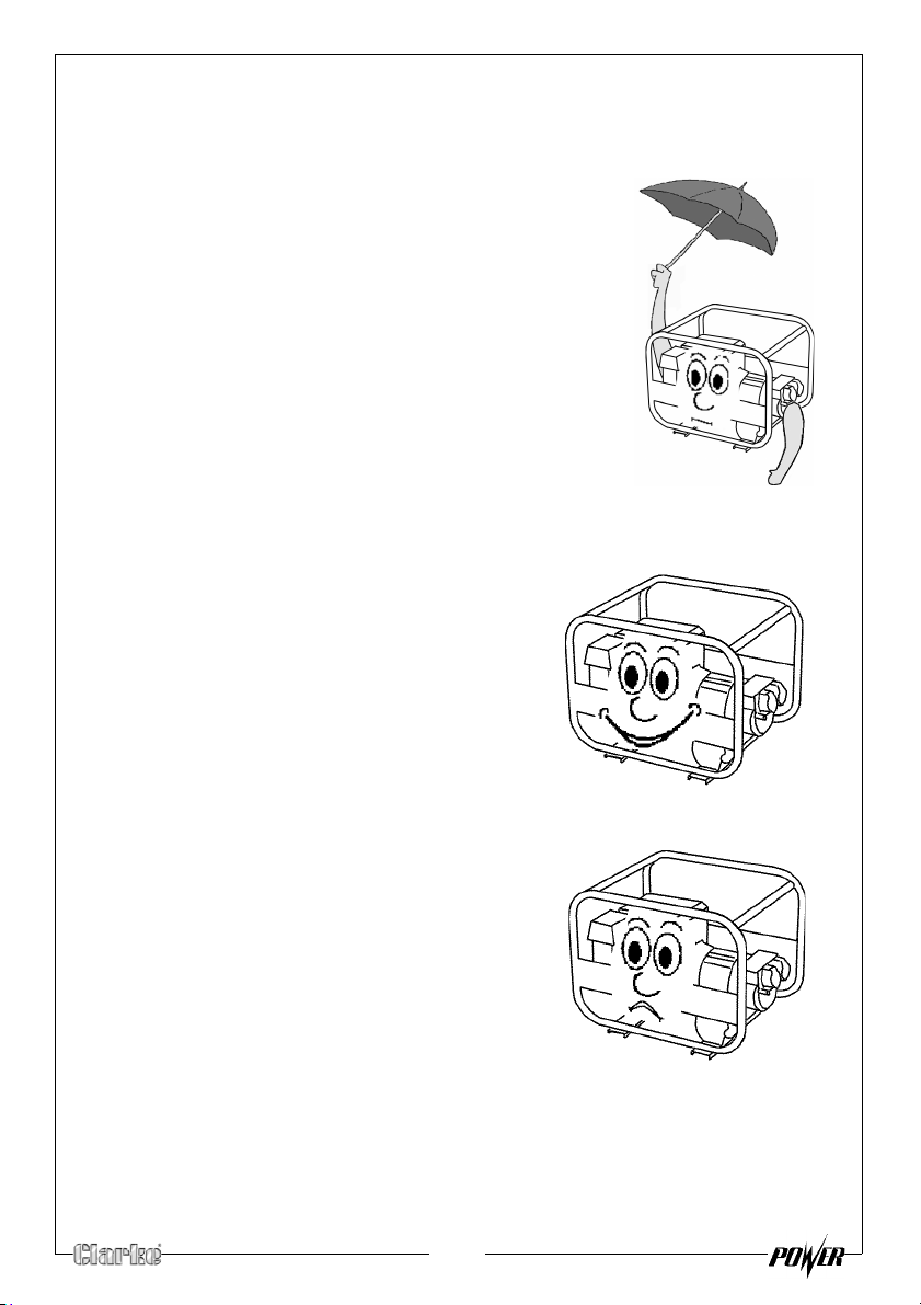
PREVENTION OF ELECTRIC SHOCK
1. Never use the generator in wet
conditions unless it is well protected/
covered. Under these conditions,
adequate ventilation MUST be provided.
2. Never operate the generator with wet
hands.
3. Never use water or any other liquids to
clean the generator.
ADDITIONAL SAFETY RULES FOR GENERATORS
1. Always ensure the applied load does
not exceed the generator rating.
Overloading t
dangerous and could cause serious
damage.
2.
Always
carrying out any maintenance.
3. Always ensure the generator reaches
operating speed before connecting a
load.
4. Never allow the generator to run out of
fuel when a load is connected.
5. Never tran
in the tank.
6. Do Not
residential power supply; eg ring main.
7. Never allow the generator air vents to
become blocked.
he generator is
disconnect the generator when
sport the generator with fuel
connect to a commercial or
4
Page 5
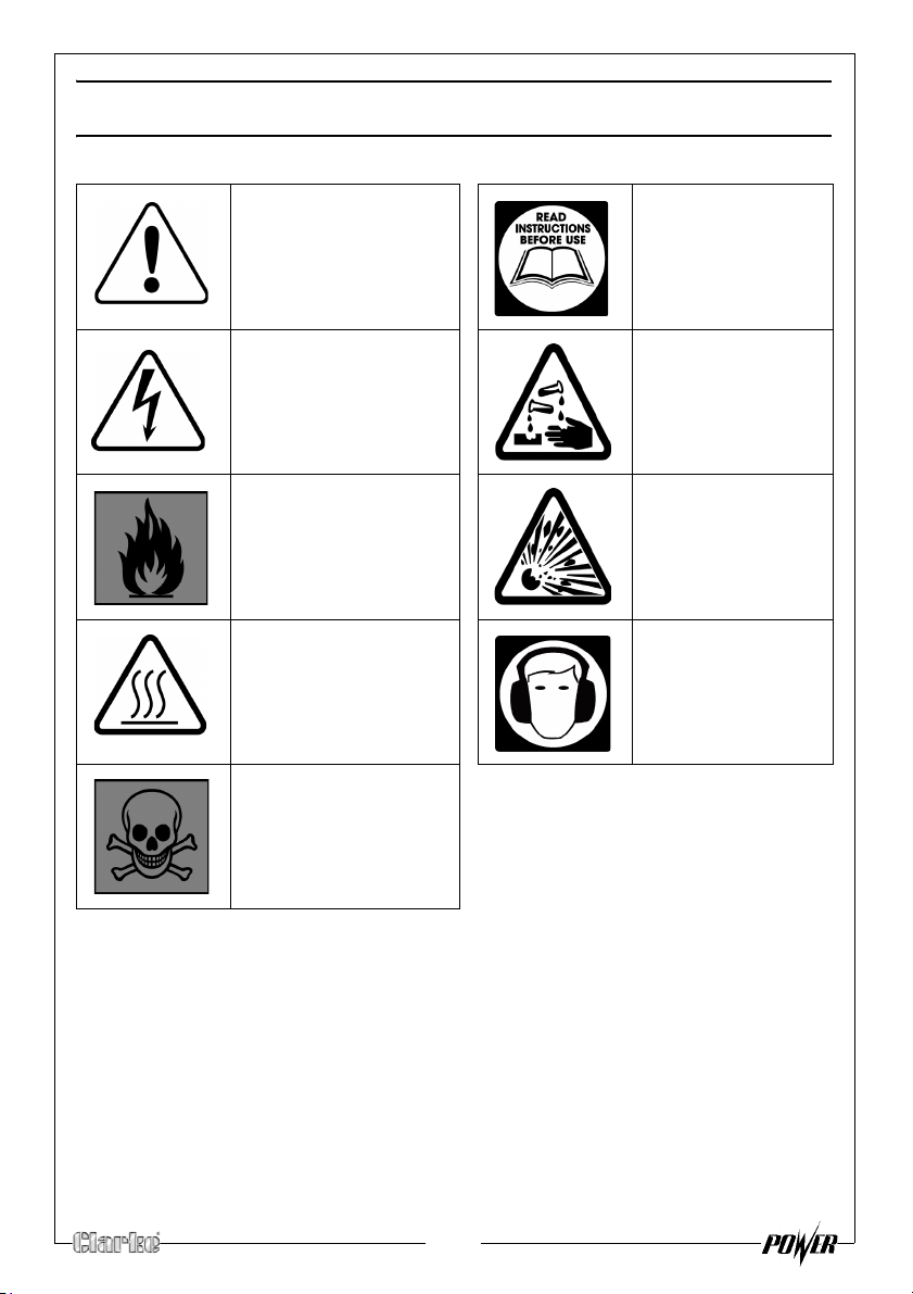
SAFETY SYMBOLS
Caution - The user
should be aware of a
general hazard
Dangerous voltage Corrosive material
Flammable Explosive risk
Hot Surface - Do not
touch
Poisonous fumes - Do
not use the
generator in an
enclosed space.
Read Instruction
manual before
use
Always wear
suitable ear
protection
5
Page 6
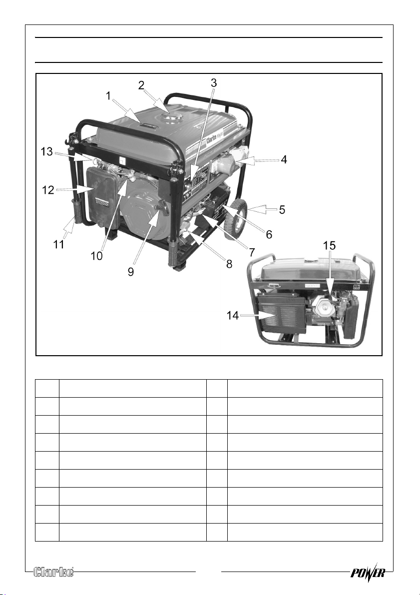
GENERATOR OVERVIEW
NO DESCRIPTION NO DESCRIPTION
1 Fuel level gauge 9 Starting handle
2 Fuel tank cap 10 Fuel supply valve
3 Ignition panel 11 Handle
4Control panel 12Air Filter
5 Wheel 13 Choke lever
6 Battery 14 Muffler
7 Dipstick 15 Spark plug
8Drain plug 16
6
Page 7
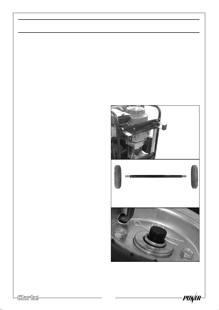
UNPACKING AND ASSEMBLY
Unpack your generator and check to ensure the following items are present.
Should there be any deficiency or damage caused during transit contact
your Clarke dealer immediately.
• The generator
• Spark plug box spanner
•Tommy bar
• Wheel kit
FITTING THE WHEEL KIT
1. Lay the generator on it’s front and
attach the 2 feet to the frame
using 4 x Short bolts, 4 x Washers,
4 x Spring washers and 4 x Nuts.
Slide both wheels on to the axle.
2.
NOTE: Make
each wheel is on the outside.
sure that the valve on
Secure the wheel to the axle using
3.
a split pin.
7
Page 8
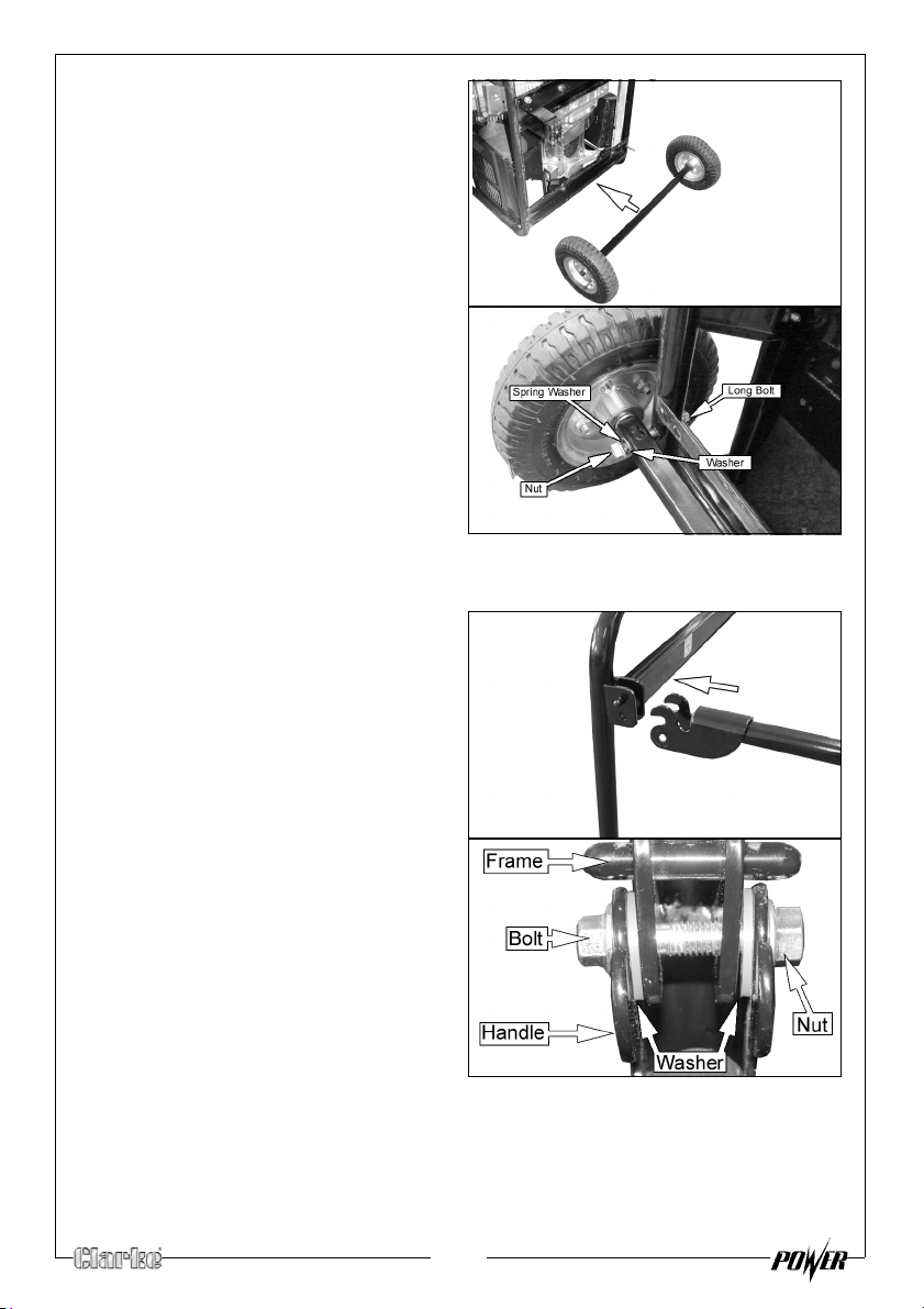
4. Place the axle against the frame
on the generator as shown.
Fix the axle to the frame using
5.
2 x Long bolts, 2 x Washers, 2 x
pring washers and 2 x Nuts.
S
6. Carefully place the generator
onto its
wheels/feet.
FITTING THE HANDLES
1. Place thehandle into position as
shown.
secure the handle using the nNut
2. S
and bolt supplied
• Making sure that the 2 plastic
w
ashers are inserted between
the handle and frame as
shown.
8
Page 9
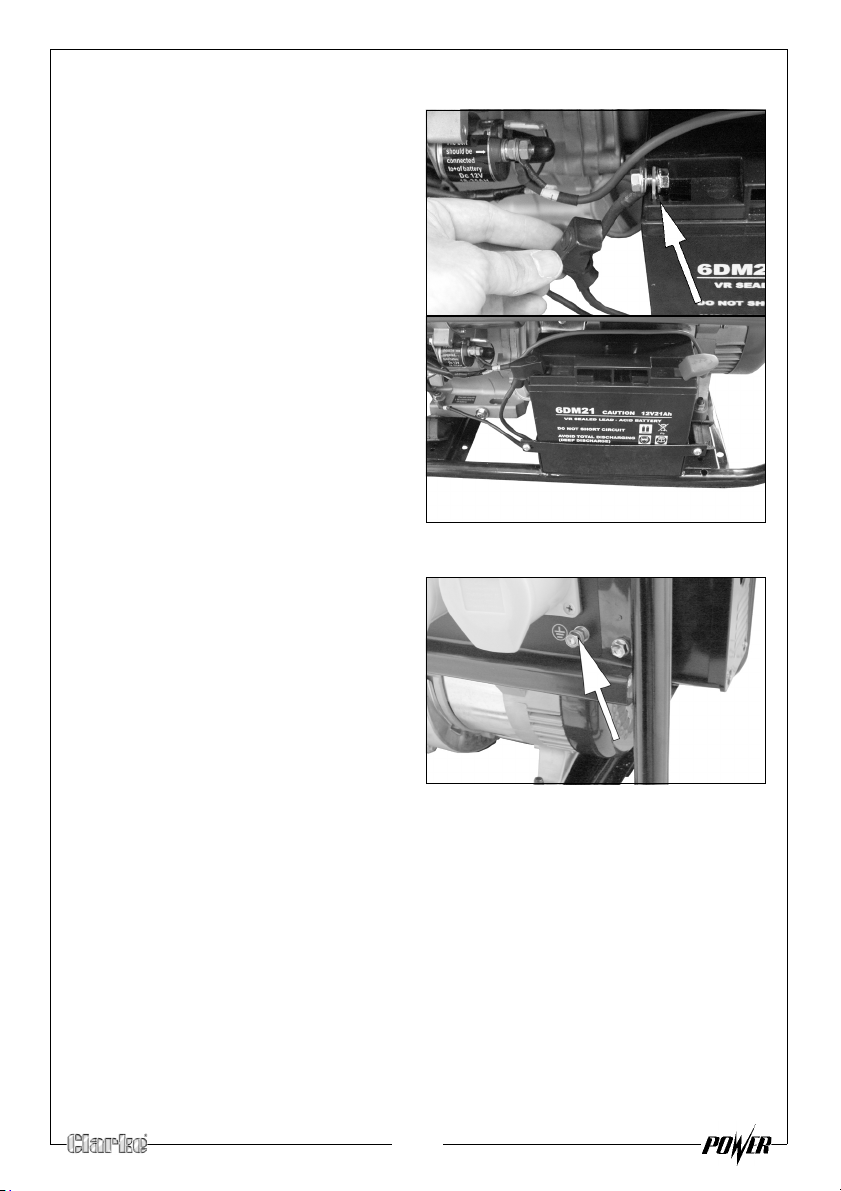
CONNECTING THE BATTERY
• Connect the negative wire to
the negative terminal on the
battery as shown on the right.
• Connect the positive wire to
the positive terminal on the
battery.
• Ensure both terminals are
covered by the plastic covers
as shown.
EARTH POINT
Always connect the generator to an
earth point. The earth terminal is
shown on the right.
9
Page 10
BEFORE USING THE GENERATOR
IMPORTANT: Generators should ALWAYS be earthed.
Attach a suitable earth lead to a good earth - water pipe, ground spike etc.,
whenever you use this generator.
Before using your generator check that:
• The generator is in good condition and free from any damage.
• The generator is clean and free from fuel or oil spillage.
• The generator is correctly located for use (See page 3).
• The fuel system and connectors are intact and there is no leakage.
NOTE: Always use a funnel to fill the fuel tank so as to avoid accidental
spillage of fuel. If fuel is spilled it must be removed from the unit
before attempting to start the engine.
WARNING: ENSURE THERE IS ADEQUATE FUEL IN THE TANK WHEN USING
THE GENERATOR. RUNNING OUT OF FUEL OR STOPPING THE ENGINE
SUDDENLY WITH A LOAD CONNECTED COULD CAUSE SERIOUS DAMAGE.
10
Page 11
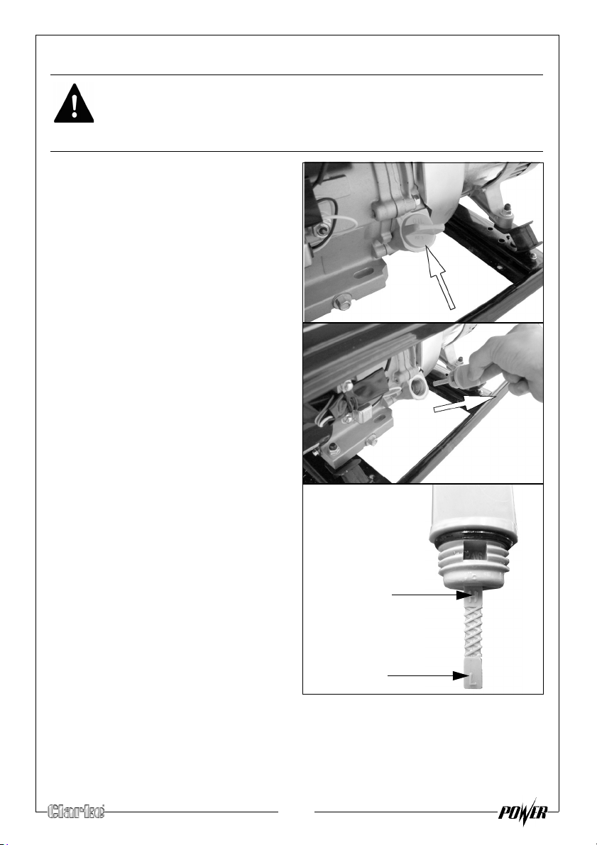
CHECKING THE ENGINE OIL LEVEL
‘H’ Level
‘L’ Level
WARNING: TO CARRY OUT THIS CHECK, PLACE THE GENERATOR ON LEVEL
GROUND WITH THE ENGINE SWITCHED OFF.
WARNING: TAKE CARE NOT TO TOUCH ANY HOT PARTS OF THE
GENERATOR WHEN CHECKING THE OIL LEVEL.
1. Turn the oil filler cap anticlockwise and remove from the oil
tank, w
clean cloth.
2.
Insert the dipstick back into the oil
filler tube and then remove it
again. Do not screw in the oil filler
cap/dipstick when doing this.
ipe the dipstick with a
3.
If the oil is below the ‘L’ level on
the dipstick, fill the oil reservoir to
the ‘H’ level on the dipstick.
• Oil capacity (See
“Specifications” on page 22.)
• We recommend the use of
SAE30 oil in this generator.
4. Replace the oil filler cap.
11
Page 12
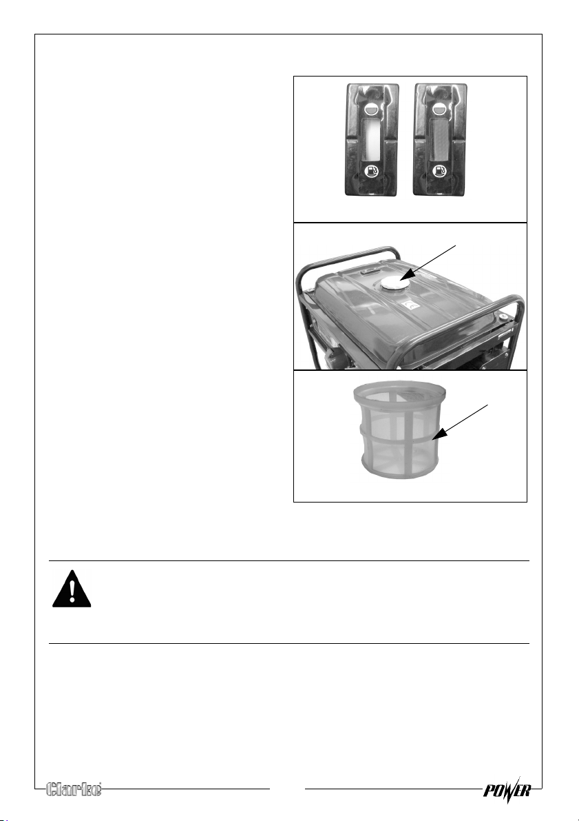
CHECKING THE FUEL LEVEL
Empty
Full
Fuel filler cap
Fuel filter
1. Check the fuel level on the fuel
gauge.
The fuel gauge will show as red
hen you have fuel in the tank
w
turning white as the fuel level
decreases
To add fuel, open the fuel filler
2.
cap.
3.
Just inside the fuel tank is a fuel
tank filter, check this filter
periodic
contaminants which may have
accumulated.
4. Slowly add fuel to the fuel tank
(maximum 25L) watching the fuel
level gauge as you do so.
.
ally and remove any
RECOMMENDED FUEL
We recommend the use of standard unleaded petrol.
WARNING: ALWAYS REFUEL IN A WELL VENTILATED AREA AWAY FROM
ANY HEAT SOURCES.
WARNING: ALLOW THE UNIT TO COOL DOWN BEFORE REFUELLING.
WARNING: DO NOT LEAVE FUEL WITHIN THE REACH OF CHILDREN.
NOTE: Do not overfill the fuel tank.
5. Replace the fuel filler cap securely.
12
Page 13
USING YOUR GENERATOR
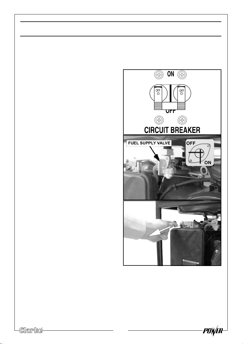
STARTING THE ENGINE
1. Remove all connections from the AC sockets.
2.
Set the AC circuit breaker to the
off position.
3. Turn on the fuel supply valve.
4.
If you are starting the generator
‘cold’ set the choke lever to the
ON position.
warm skip this step.
If the generator is
13
Page 14
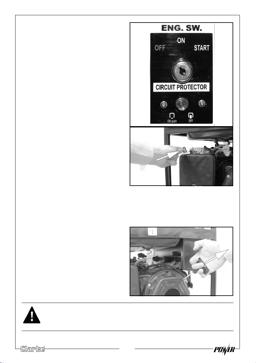
5. Insert the key into the ignition.
6. Turn and hold the key in the START
po
sition.
7. Once the engine starts to run turn
the key back to the ON position.
Once the engine has warmed up,
8.
set the choke lever to the OFF
position pushed in).
BACKUP STARTING PROCEDURE
If for any reason the engine will not start using the above pr
start your generator manually by carrying out the following.
1.
Set the ignition key to the ON
position.
2. Pull the starting handle lightly until
you start to feel resistance and
then pull up sharply to start the
generator.
3. You may have to do this more
than once.
.
WARNING: ONCE THE GENERATOR HAS STARTED, RELEASE THE STARTING
HANDLE SLOWLY TO AVOID INJURY/DAMAGE AS IT WHIPS BACK.
14
ocedure, you can
Page 15
CONNECTING ELECTRICAL DEVICES
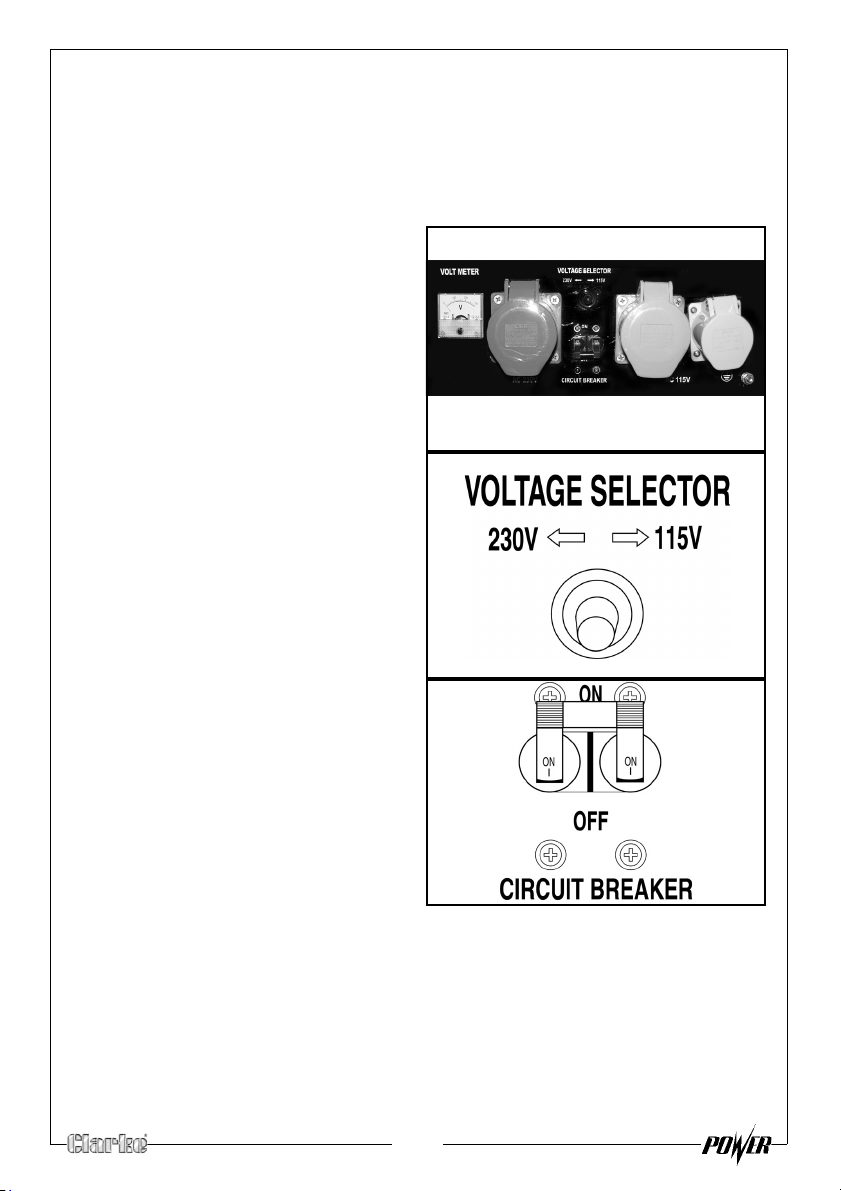
The generator can supply both 230V AC and 115V AC.
The ports are laid out in the following order: (from left to right):
1 x 32amp 230v (Blue),1 x 32amp 115v (Large Yellow) and 1 x 16amp 115v
(Small Yellow).
1. Connect the appliance to the
generator starting with the device
that draws the most current.
2. Select the voltage that you
require using the voltage selector
switch.
3. Set the circuit breaker to ‘ON’.
15
Page 16
SHUTTING DOWN THE GENERATOR
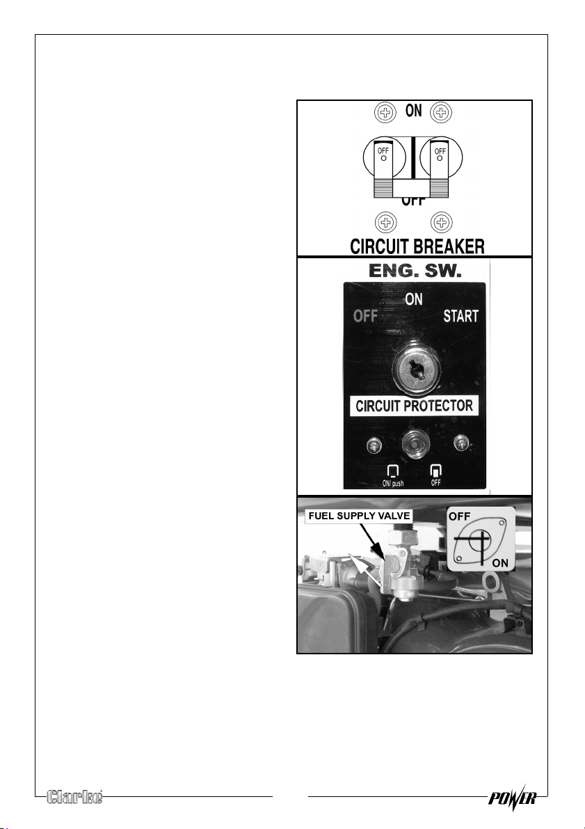
1. Disconnect all appliances connected to the generator.
2.
Set the circuit breaker to ‘OFF’.
3. Turn the ignition key to the OFF
position.
4. Set the fuel supply valve to OFF.
NOTE: T
o stop the generator in an
emergency simply turn the
ignition key to the off position.
16
Page 17
MAINTENANCE
CHANGING THE ENGINE OIL
CAUTION: PROLONGED EXPOSURE TO USED ENGINE OIL IS DANGEROUS,
ALWAYS WASH YOUR HANDS THOROUGHLY AFTER HANDLING USED
ENGINE OIL.
1. Unscrew and remove the oil filler cap/dipstick.
2. Place an oil collection tray under the drain plug.
3. Unscrew the drain plug, and allow the used engine oil to drain from the
crankcase into the oil collection tray.
NOTE: Drain the engine oil when the engine is warm, this will ensure the
oil flows out quicker.
4. Replace the drain plug and it ring seal.
5. Fill the crankcase with engine oil to the ‘H’ mark on the dipstick. See
page 11.
6. Replace the oil filler cap/dipstick.
ENVIRONMENTAL PROTECTION
One of the most damaging sources of pollution is oil, Do not throw away used
engine oil in with your domestic trash or down drains and sinks. Place it in a
leak proof container and take it to your local waste disposal site.
17
Page 18
CHANGING THE SPARK PLUGS
Add pic
CAUTION: ALLOW THE ENGINE TO COOL BEFORE REMOVING THE SPARK
PLUG.
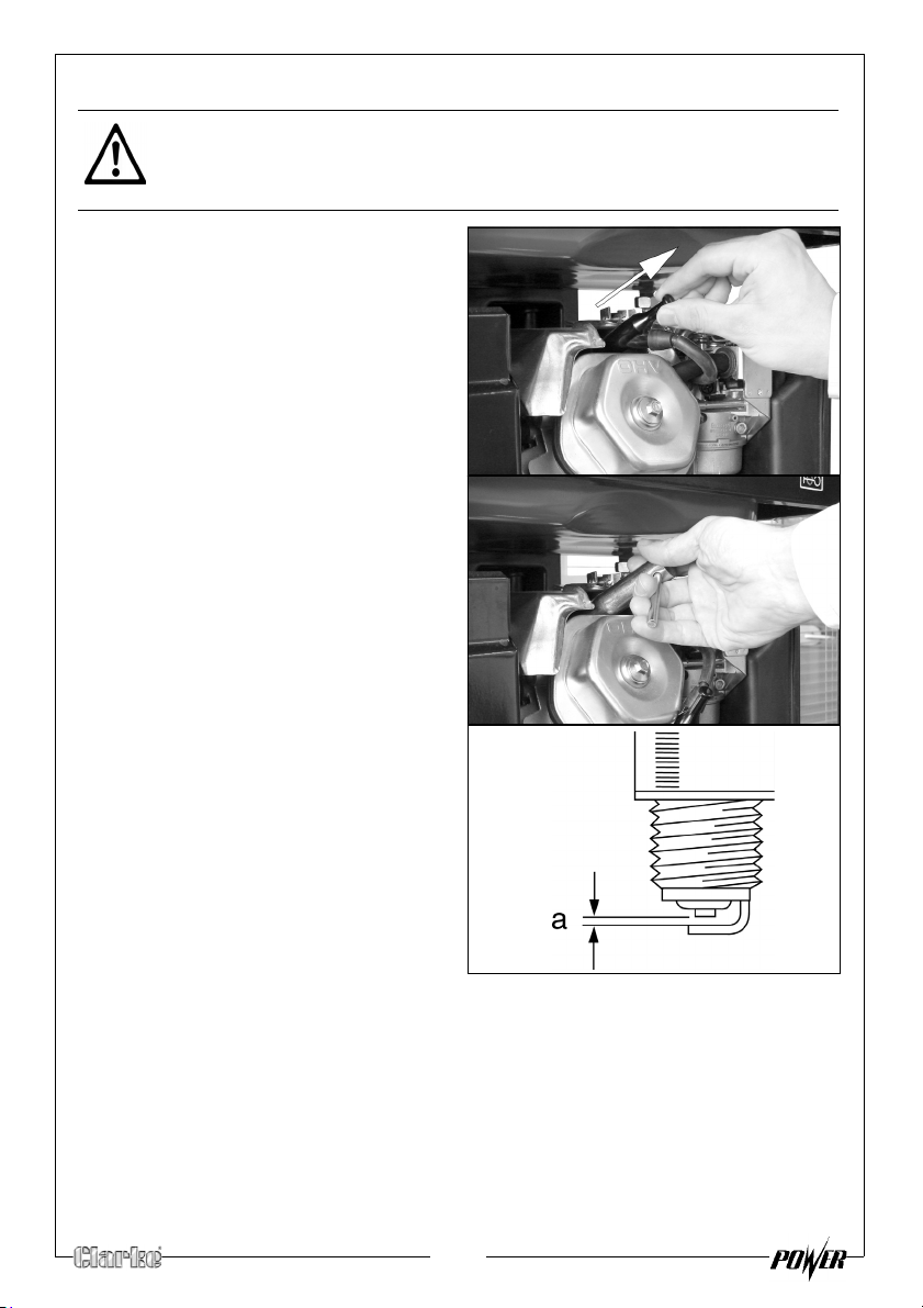
1. Remove the spark plug cap from
the spark plug.
2.
Use the supplied spark plug
spanner to remove the spark plug.
3. Remove any carbon that has
acc
umulated around the
sparkplug.
Check the spark plug gap (a), it
4.
should be between 0.7 and 0.8
mm, adjust if necessary.
5. Check the overall condition of the
sp
ark plug and replace if
necessary.
6. Reinstall the spark plug and
replace the spark plug cap.
18
Page 19
CHECKING THE AIR FILTER
CAUTION: DO NOT USE THE GENERATOR WITHOUT THE AIR FILTER FITTED,
THIS CAN DAMAGE THE GENERATOR.
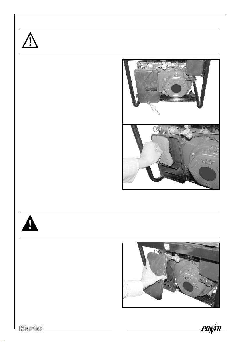
1. Unlock and remove the air filter
cover.
2. Remove the air filter element.
3. Make sure that the air filter is
clean and not
• If the air filter is damaged
co
ntact Clarke spare parts
department for a replacement.
• If the filter is dirty, wash the filter
in a solution of warm water and
mild detergent and rinse
thoroughly. Leave the filter to
dry completely, once it is dry immerse the filter in clean engine oil
and sqeeze the filter to remove excess oil.
damaged.
WARNING: DO NOT USE INFLAMMABLE SOLVENTS OR PETROL TO CLEAN
THE AIR FILTER.
Replace the filter back into its
4.
original position and replace the
air filter cover.
19
Page 20
CLEANING THE FUEL VALVE FILTER / DRAINING THE FUEL TANK
Add pic
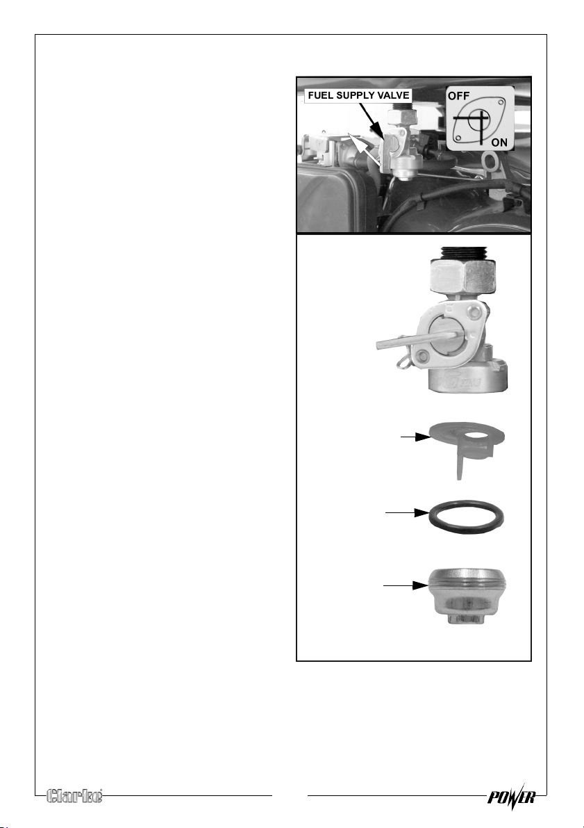
VALVE FILTER
‘O’ RING
CUP
1. Set the fuel supply valve to OFF.
2. U
nscrew and remove the cup,
then remove the valve filter and
‘O’ ring
3. Wash these parts in a noninflammable
that the valve filter is not
damaged.
4. Place an approved petrol storage
container under the fuel valve
and set the fuel supply valve to
‘ON’.
• The fuel in the tank will drain
5. Replace the ‘O’ ring and valve
filter and
possible.
.
solvent. Make sure
into the container.
tighten the cup as far as
20
Page 21
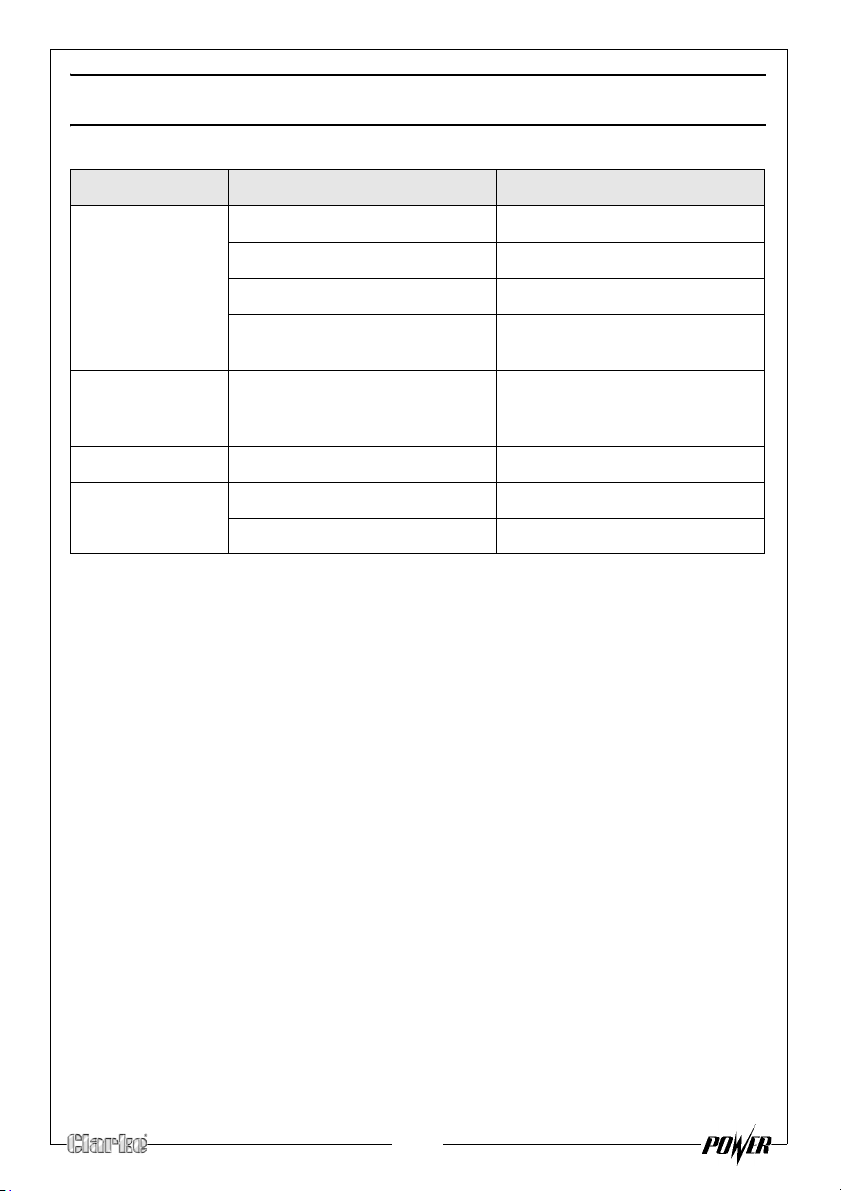
TROUBLESHOOTING
PROBLEM CAUSE SOLUTION
The generator fails
o start
t
The generator fails
generate
to
electricity
The generator is
ifficult to start
d
Ignition switch is off Set the ignition switch to ‘on’
Not enough oil in the generator Add more oil, See page 11
No fuel Add more fuel, See page 12
Spark plugs not working correctly Change the spark plugs, See
page 18
The device you are trying to
power is faulty
The AC breaker is switched off Switch the AC breaker on
The air filter is dirty Clean the air filter, See page 19
The fuel filter is dirty Clean the fuel filter, See page 20
Make sure the device you want
to power is working properly
If this does not solve your problem, please contact the Clarke service
department. See page 27
21
Page 22
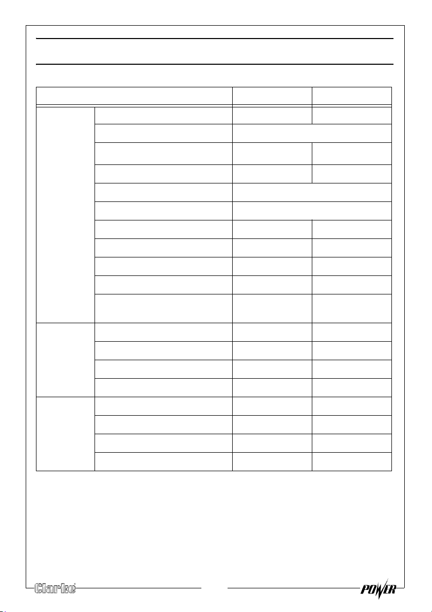
SPECIFICATIONS
FG4050ES FG5100ES
Engine Engine Model 182FD 188FD
Type Petrol
3
Displacement (cm
Max. power output (hp/rpm) 11/3600 13/3600
Ignition type Non contact transisterised ignition
Start system Electric with recoil backup
Fuel tank capacity (L) 25 25
Fuel consumption (L/hr.) 2.45 2.7
Maximum run time (h) 10 9
Engine oil capacity (L) 1.1 1.1
Guaranteed sound power (L
dB)
Generator Rated Frequency (Hz) 50 50
Output Voltage (V) 115v / 230v 115v / 230v
Rated Power (kVA) 4 5
Max. Power (kVA) 4.5 5.5
Dimensions Length (mm) 680 680
Width (mm) 540 540
Height (mm) 510 510
)
WA
337 389
97 97
Unpacked Weight (kg) 84.5 82
22
Page 23
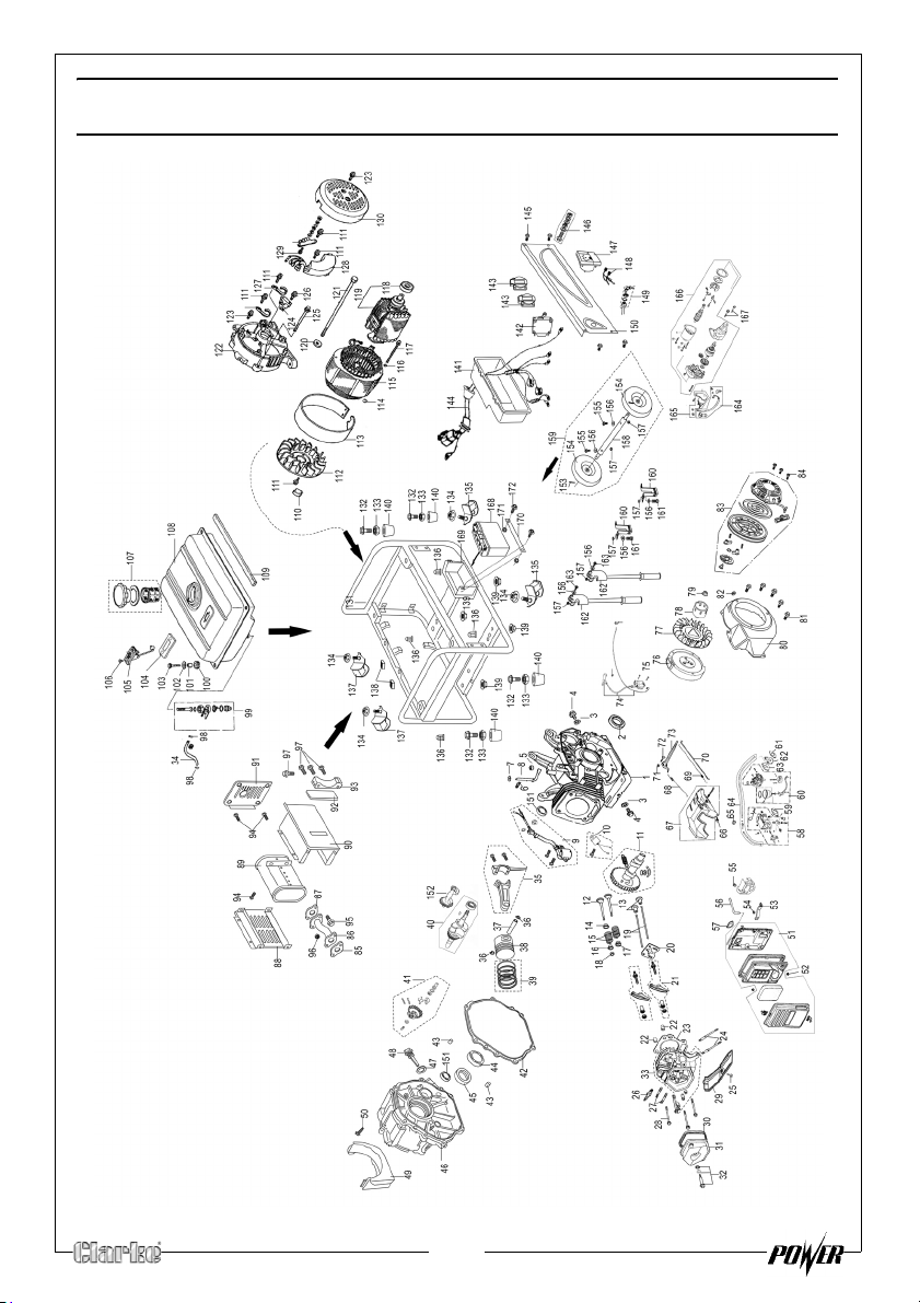
EXPLODED DIAGRAM & PARTS LIST
23
Page 24
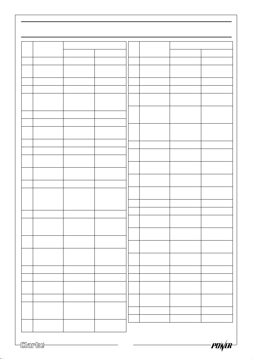
EXPLODED DIAGRAM & PARTS LIST
NO DESCRIPTION PAR T NO
FG4050ES FG5100ES
1 Crankcase RKFG4010001 RKFG5100001
2 Oil seal,
crankshaft
3 Wa sh er RKFG4010003 RKFG5100003
4 Drain plug RKFG4010004 RKFG5100004
5 Oil seal,
regulating
sway bar
6 Split pin RKFG4010006 RKFG5100006
7 Wa sh er RKFG4010007 RKFG5100007
8 Regulating
sway bar
9 Oil sensor RKFG4010009 RKFG5100009
10 Diode RKFG4010010 RKFG5100010
11 Camshaft
Assy
12 Exhaust
valve
13 Intake valve RKFG4010013 RKFG5100013
14 Spring
retainer,
exhaust
valve
15 Val v e s p ring RKFG4010015 RKFG5100015
16 Spring seat,
exhaust
valve
17 Spring seat,
intake valve
18 Cap,
exhaust
valve
19 Pusher RKFG4010019 RKFG5100019
20 Pusher guide RKFG4010020 RKFG5100020
21 Valve rocker
Assy
22 Set pin RKFG4010022 RKFG5100022
23 Gasket,
cylinder
head
24 Stud
M6×M8×106
RKFG4010002 RKFG5100002
RKFG4010005 RKFG5100005
RKFG4010008 RKFG5100008
RKFG4010011 RKFG5100011
RKFG4010012 RKFG5100012
RKFG4010014 RKFG5100014
RKFG4010016 RKFG5100016
RKFG4010017 RKFG5100017
RKFG4010018 RKFG5100018
RKFG4010021 RKFG5100021
RKFG4010023 RKFG5100023
RKFG4010024 RKFG5100024
NO DESCRIPTION PART NO
FG4050ES FG5100ES
25 Bolt M6×12 RKFG4010025 RKFG5100025
26 Spark plug
F6RTCU
27 Stud M8×35 RKFG4010027 RKFG5100027
28 Flange bolt RKFG4010028 RKFG5100028
29 Lead wind
cover
30 Gasket,
cylinder
head cover
31 Cylinder
head cover
Assy
32 Bolt RKFG4010032 RKFG5100032
33 Cylinder
head Assy
34 Outlet pipe
9×4.5×160
35 Connecting
rod Assy
36 Piston pin
circlip
37 Piston pin RKFG4010037 RKFG5100037
38 Piston RKFG4010038 RKFG5100038
39 Piston ring
assy
40 Crankshaft
sets
41 Driven gear
set, regulator
42 Gasket,
crankcase
43 Set pin RKFG4010043 RKFG5100043
44 Bearing 6207 RKFG4010044 RKFG5100044
45 Oil seal,
crankshaft
46 Crankcase
cover
47 Dipstick RKFG4010047 RKFG5100047
48 Seal RKFG4010048 RKFG5100048
RKFG4010026 RKFG5100026
RKFG4010029 RKFG5100029
RKFG4010030 RKFG5100030
RKFG4010031 RKFG5100031
RKFG4010033 RKFG5100033
RKFG4010034 RKFG5100034
RKFG4010035 RKFG5100035
RKFG4010036 RKFG5100036
RKFG4010039 RKFG5100039
RKFG4010040 RKFG5100040
RKFG4010041 RKFG5100041
RKFG4010042 RKFG5100042
RKFG4010045 RKFG5100045
RKFG4010046 RKFG5100046
24
Page 25
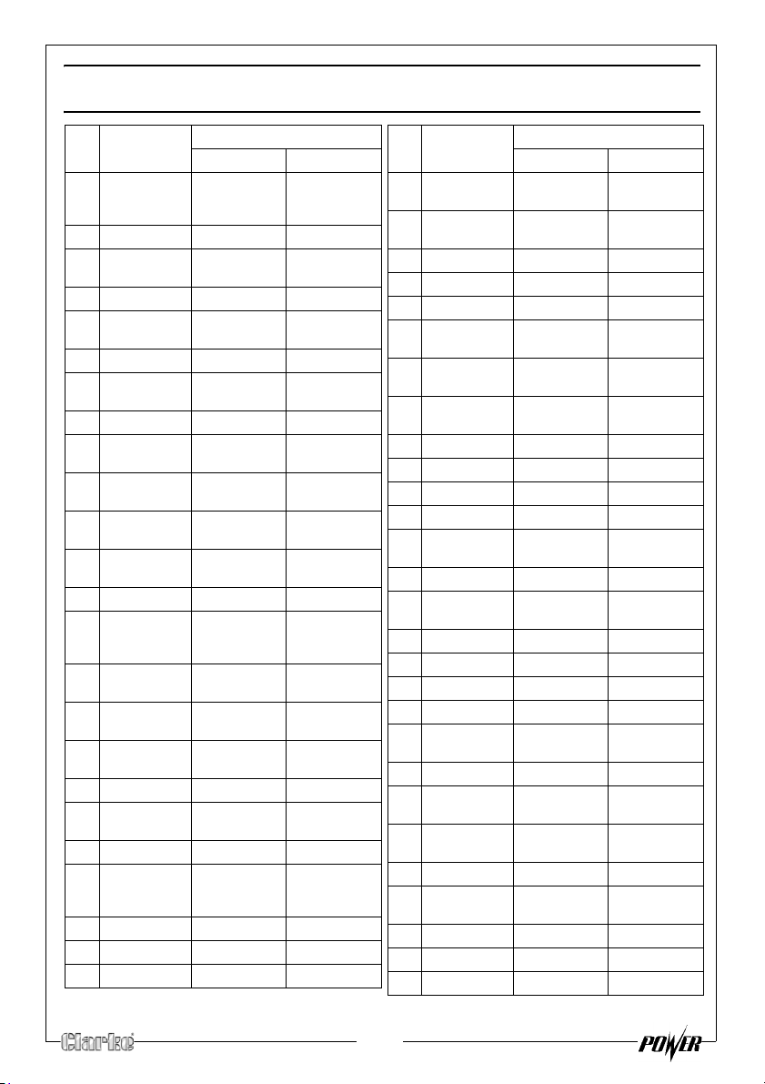
EXPLODED DIAGRAM & PARTS LIST
NO DESCRIPTION PART NO
FG4050ES FG5100ES
49 Guard,
crankcase
cover
50 Bolt M5×12 RKFG4010050 RKFG5100050
51 Air cleaner
Assy
52 Nut M5 RKFG4010052 RKFG5100052
53 Air cleaner
stay
54 Nut M6 RKFG4010054 RKFG5100054
55 Boot, vent
pipe
56 Air duck RKFG4010056 RKFG5100056
57 Gasket, air
cleaner
58 Manual
choke Assy
59 Gasket, air
cleaner
60 Carburetor
Assy
61 Gasket, inlet RKFG4010061 RKFG5100061
62 Connecting
block,
carburetor
63 Gasket,
carburetor
64 Check valve
Assy
65 Clamp,
check valve
66 Bolt M6×12 RKFG4010066 RKFG5100066
67 Supporting
plate set
68 Back spring RKFG4010068 RKFG5100068
69 Fine
regulating
spring
70 Pulling rod RKFG4010070 RKFG5100070
71 Nut M6 RKFG4010071 RKFG5100071
72 Lock bolt RKFG4010072 RKFG5100072
RKFG4010049 RKFG5100049
RKFG4010051 RKFG5100051
RKFG4010053 RKFG5100053
RKFG4010055 RKFG5100055
RKFG4010057 RKFG5100057
RKFG4010058 RKFG5100058
RKFG4010059 RKFG5100059
RKFG4010060 RKFG5100060
RKFG4010062 RKFG5100062
RKFG4010063 RKFG5100063
RKFG4010064 RKFG5100064
RKFG4010065 RKFG5100065
RKFG4010067 RKFG5100067
RKFG4010069 RKFG5100069
NO DESCRIPTION PART NO
FG4050ES FG5100ES
73 Regulating
arm
74 Ignition coil
unit
75 Bolt M6×30 RKFG4010075 RKFG5100075
76 Flywheel RKFG4010076 RKFG5100076
77 Flywheel fan RKFG4010077 RKFG5100077
78 Starting
flange
79 Nut
M16×1.25
80 Fan hood
assy
81 Bolt M6×12 RKFG4010081 RKFG5100081
82 Grommet RKFG4010082 RKFG5100082
83 Recoil starter RKFG4010083 RKFG5100083
84 Bolt M6×8 RKFG4010084 RKFG5100084
85 Gasket,
outlet
86 Exhaust pipe RKFG4010086 RKFG5100086
87 Gasket,
exhaust pipe
88 Outer hood RKFG4010088 RKFG5100088
89 Muffler RKFG4010089 RKFG5100089
90 Inner hood RKFG4010090 RKFG5100090
91 Side hood RKFG4010091 RKFG5100091
92 Gasket, inner
hood
93 Muffler stay RKFG4010093 RKFG5100093
94 Flange bolt
M6×12
95 Flange bolt
M8×25
96 Nut M8 RKFG4010096 RKFG5100096
97 Flange bolt
M8×16
98 Tube clip RKFG4010098 RKFG5100098
99 Fuel cock RKFG4010099 RKFG5100099
100 Cushion RKFG4010100 RKFG5100100
RKFG4010073 RKFG5100073
RKFG4010074 RKFG5100074
RKFG4010078 RKFG5100078
RKFG4010079 RKFG5100079
RKFG4010080 RKFG5100080
RKFG4010085 RKFG5100085
RKFG4010087 RKFG5100087
RKFG4010092 RKFG5100092
RKFG4010094 RKFG5100094
RKFG4010095 RKFG5100095
RKFG4010097 RKFG5100097
25
Page 26
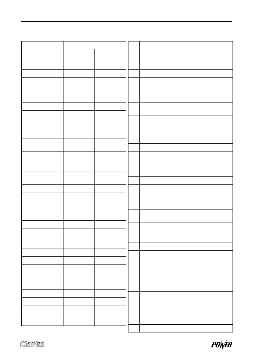
EXPLODED DIAGRAM & PARTS LIST
NO DESCRIPTION PART NO
FG4050ES FG5100ES
101 Fitting brush,
fuel tank
102 Washe r RKFG4010102 RKFG5100102
103 Flange bolt
M6×22
104 Gasket, fuel
sensor
105 Fuel sensor RKFG4010105 RKFG5100105
106 Screw
M5×10
107 Fuel filler cap RKFG4010107 RKFG5100107
108 Fuel tank RKFG4010108 RKFG5100108
109 Stripe, fuel
tank
110 Plug, sump RKFG4010110 RKFG5100110
111 Screw
M5×14
112 Generator
fan
113 Stator cover RKFG4010113 RKFG5100113
114 Nut M5 RKFG4010114 RKFG5100114
115 Stator Assy RKFG4010115 RKFG5100115
116 Spring
washer 5mm
117 Bolt M5×213 RKFG4010117 RKFG5100117
118 Bearing
6204-2ZN
119 Rotor Assy RKFG4010119 RKFG5100119
120 Plain washer RKFG4010120 RKFG5100120
121 Bolt M10×265 RKFG4010121 RKFG5100121
122 Generator
stay
123 Screw
M5×12
124 Brush Assy RKFG4010124 RKFG5100124
125 Bolt M6×175 RKFG4010125 RKFG5100125
126 Screw
M5×18
127 Clip A RKFG4010127 RKFG5100127
RKFG4010101 RKFG5100101
RKFG4010103 RKFG5100103
RKFG4010104 RKFG5100104
RKFG4010106 RKFG5100106
RKFG4010109 RKFG5100109
RKFG4010111 RKFG5100111
RKFG4010112 RKFG5100112
RKFG4010116 RKFG5100116
RKFG4010118 RKFG5100118
RKFG4010122 RKFG5100122
RKFG4010123 RKFG5100123
RKFG4010126 RKFG5100126
NO DESCRIPTION PART NO
FG4050ES FG5100ES
128 Vo lt a ge
regulator
129 Bolt M5×20 RKFG4010129 RKFG5100129
130 Generator
end cover
131 Frame
comp.
132 Rubber pad,
frame
133 Bolt M6×12 RKFG4010133 RKFG5100133
134 Nut M6 RKFG4010134 RKFG5100134
135 Bottom
rubber A
136 Nut M6 RKFG4010136 RKFG5100136
137 Bottom
rubber B
138 Rubber pad,
frame
139 Nut M8 RKFG4010139 RKFG5100139
140 Cushion,
frame
141 Control
panel case
142 Circuit
protector
143 Consent RKFG4010143 RKFG5100143
144 Main wire
harness Assy
145 Bolt M6×12 RKFG4010145 RKFG5100145
146 Earth
terminal set
147 Vo lt m et er RKFG4010147 RKFG5100147
148 DC terminal RKFG4010148 RKFG5100148
149 Ignition
switch
150 Control
panel
151 Bearing 6202 RKFG4010151 RKFG5100151
152 Balancing
shaft
153 Split pin RKFG4010153 RKFG5100153
RKFG4010128 RKFG5100128
RKFG4010130 RKFG5100130
RKFG4010131 RKFG5100131
RKFG4010132 RKFG5100132
RKFG4010135 RKFG5100135
RKFG4010137 RKFG5100137
RKFG4010138 RKFG5100138
RKFG4010140 RKFG5100140
RKFG4010141 RKFG5100141
RKFG4010142 RKFG5100142
RKFG4010144 RKFG5100144
RKFG4010146 RKFG5100146
RKFG4010149 RKFG5100149
RKFG4010150 RKFG5100150
RKFG4010152 RKFG5100152
26
Page 27
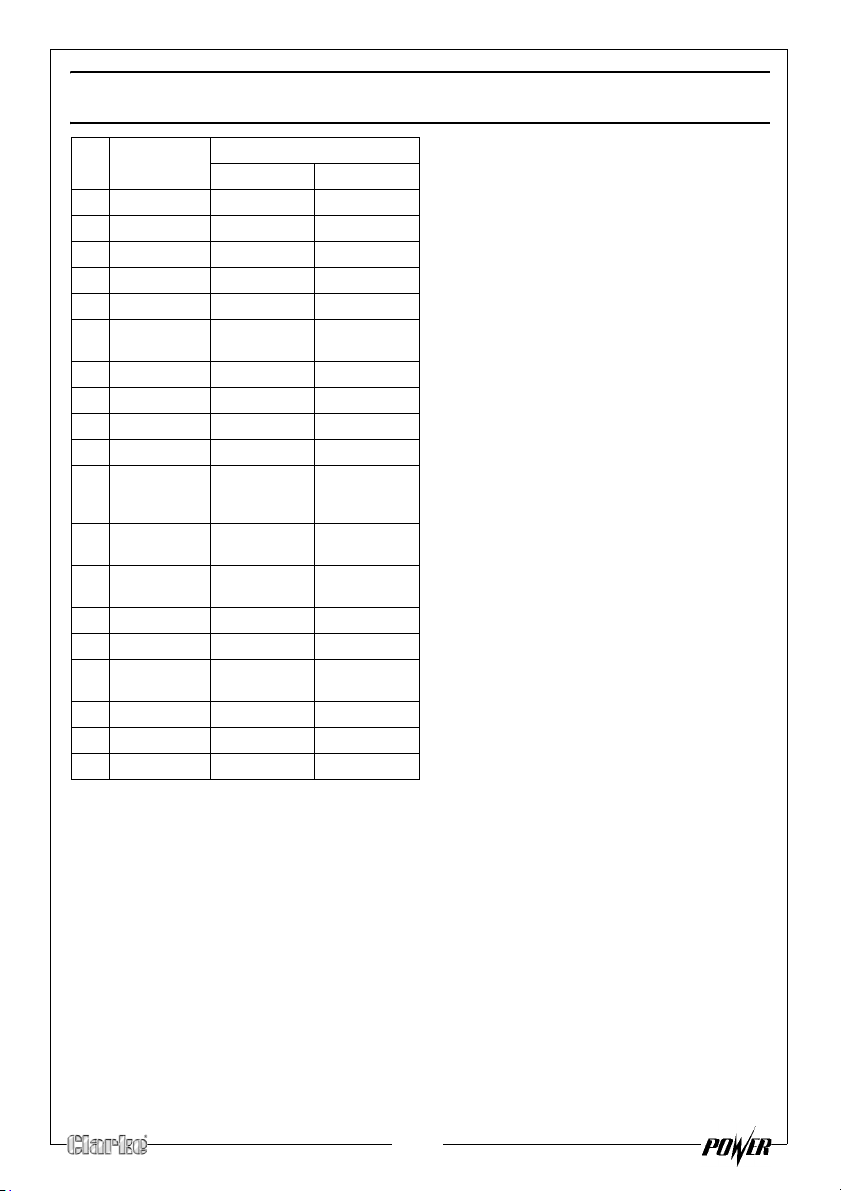
EXPLODED DIAGRAM & PARTS LIST
NO DESCRIPTION PART NO
FG4050ES FG5100ES
154 Wheel kit RKFG4010154 RKFG5100154
155 Bolt M8×60 RKFG4010155 RKFG5100155
156 Flat washer RKFG4010156 RKFG5100156
157 Screw M8 RKFG4010157 RKFG5100157
158 Wheel axel RKFG4010158 RKFG5100158
159 Wheel kit
Assy
160 Underprop RKFG4010160 RKFG5100160
161 Bolt M8×24 RKFG4010161 RKFG5100161
162 Handle bar RKFG4010162 RKFG5100162
163 Bolt M8×40 RKFG4010163 RKFG5100163
164 Cable,
starting
motor
165 Relay, start-upRKFG4010165 RKFG5100165
RKFG4010159 RKFG5100159
RKFG4010164 RKFG5100164
166 Starting
motor Assy
167 Bolt M8×35 RKFG4010167 RKFG5100167
168 Battery RKFG4010168 RKFG5100168
169 Battery
Bracket
170 Dam Board RKFG4010170 RKFG5100170
171 Nut RKFG4010171 RKFG5100171
172 Bolt M6x12 RKFG4010172 RKFG5100172
RKFG4010166 RKFG5100166
RKFG4010169 RKFG5100169
For Parts & Servicing, please contact
CLARKE International, on one of the
following numbers.
PARTS & SERVICE TEL: 020 8988 7400
PARTS & SERVICE FAX: 020 8558 3622
or e-mail as follows:
PARTS: [email protected]
SERVICE: [email protected]
27
Page 28
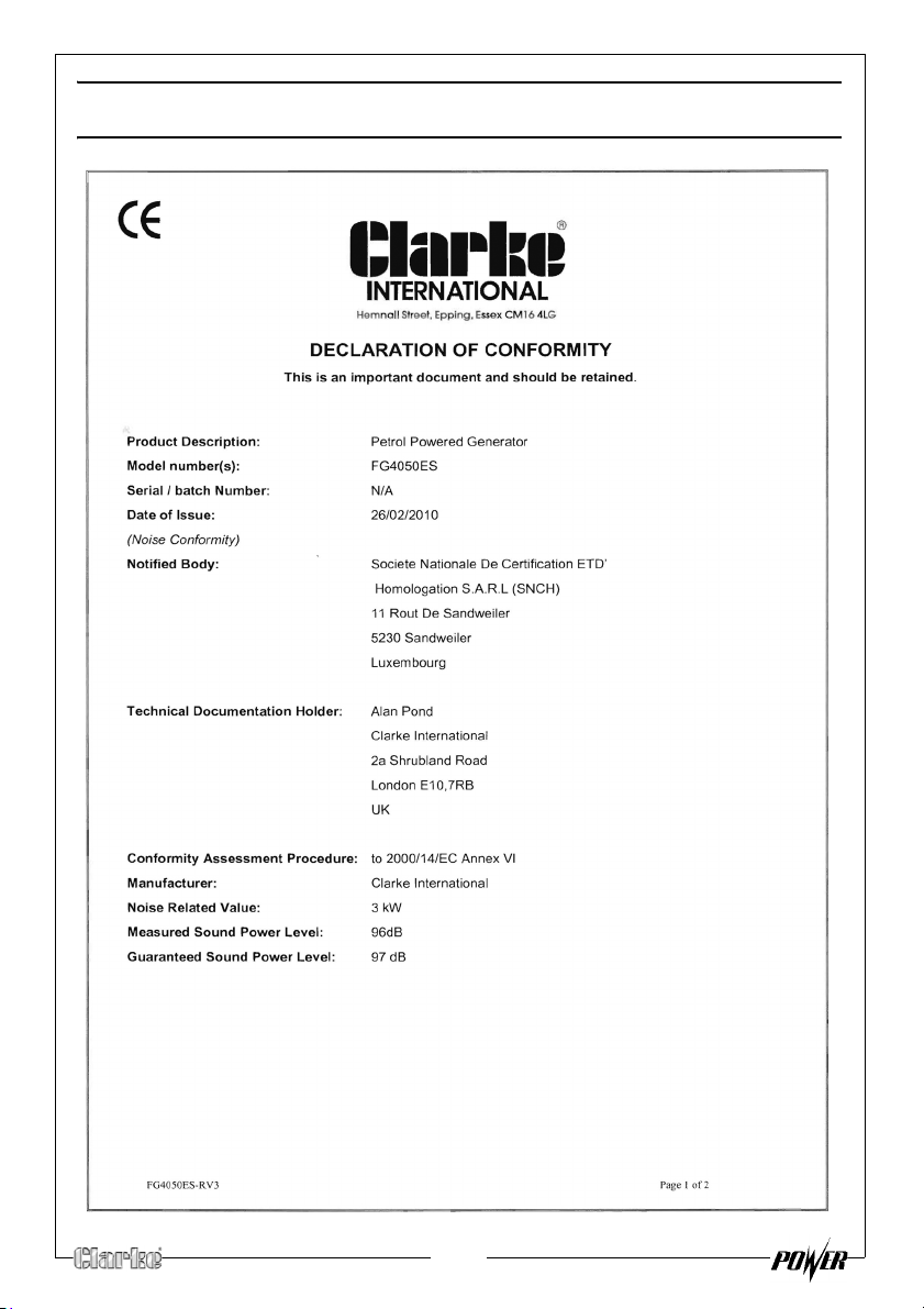
DECLARATION OF CONFORMITY (FG4050ES)
28
Page 29
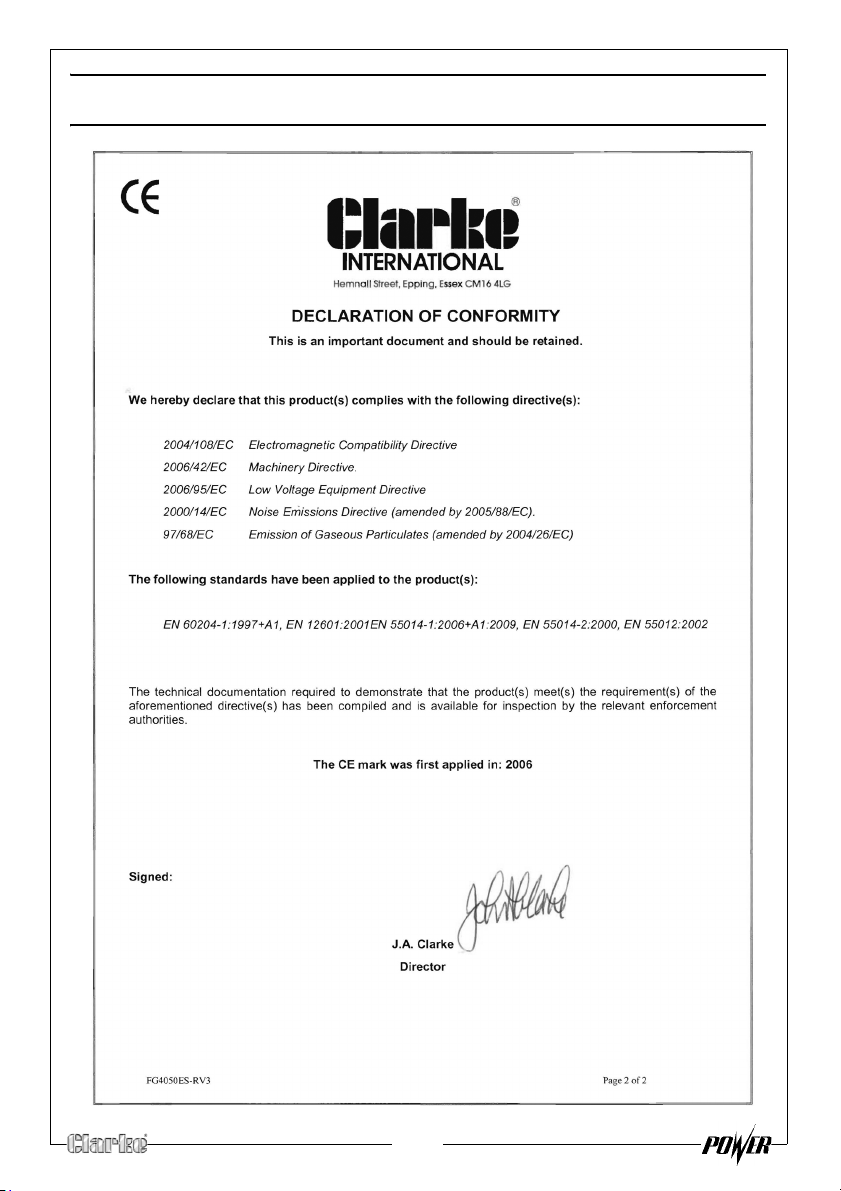
DECLARATION OF CONFORMITY (FG4050ES)
29
Page 30
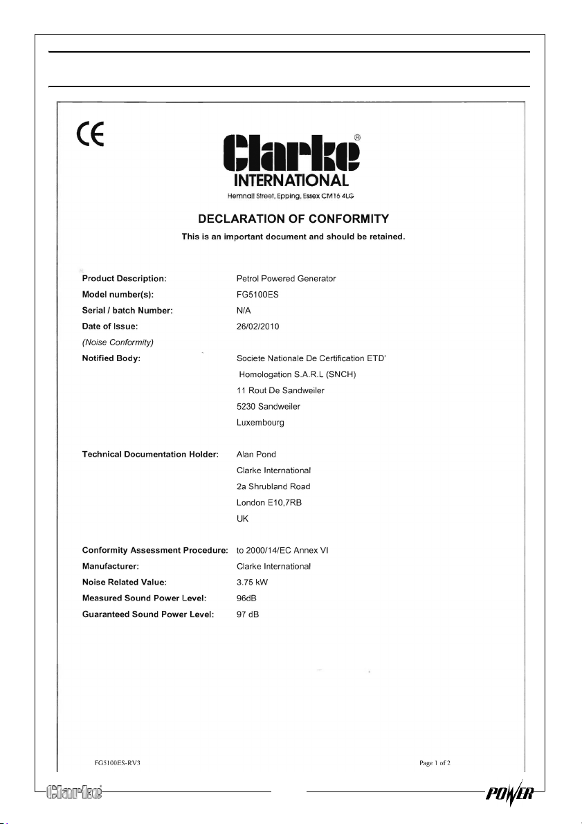
DECLARATION OF CONFORMITY (FG5100ES)
30
Page 31
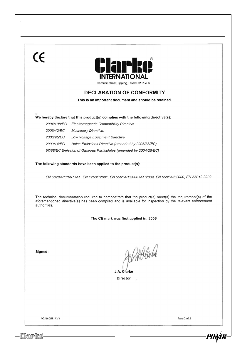
DECLARATION OF CONFORMITY (FG5100ES)
31
Page 32
 Loading...