

Page 1
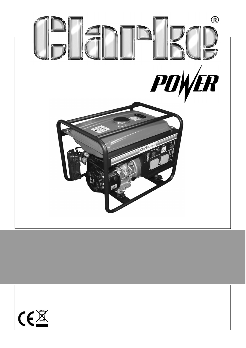
GENERATOR
MODEL NO: FG3005
PART NO: 8857707
OPERATION & MAINTENANCE
INSTRUCTIONS
LS0114
Page 2
INTRODUCTION
Thank you for purchasing this CLARKE Generator.
Before attempting to use this product, please read this manual thoroughly and
follow the instructions carefully. In doing so you will ensure the safety of yourself
and that of others around you, and you can look forward to your purchase
giving you long and satisfactory service.
GUARANTEE
This product is guaranteed against faulty manufacture for a period of 12
months from the date of purchase. Please keep your receipt which will be
required as proof of purchase.
This guarantee is invalid if the product is found to have been abused or
tampered with in any way, or not used for the purpose for which it was
intended.
Faulty goods should be returned to their place of purchase, no product can
be returned to us without prior permission.
This guarantee does not effect your statutory rights.
ENVIRONMENTAL RECYCLING POLICY
Through purchase of this product, the customer is taking on the
obligation to deal with the WEEE in accordance with the WEEE
regulations in relation to the treatment, recycling & recovery and
environmentally sound disposal of the WEEE.
In effect, this means that this product must not be disposed of with general
household waste. It must be disposed of according to the laws governing
Waste Electrical and Electronic Equipment (WEEE) at a recognised disposal
facility.
2
Parts & Service: 020 8988 7400 / E-mail: [email protected] or [email protected]
Page 3

TABLE OF CONTENTS
INTRODUCTION .....................................................................2
GUARANTEE ..........................................................................2
ENVIRONMENTAL RECYCLING POLICY ...............................2
TABLE OF CONTENTS .............................................................3
GENERAL SAFETY RULES .......................................................4
Work area ............................................................................. 4
Positioning the generator ................................................... 4
Fire prevention ..................................................................... 4
Prevention of electric shock .............................................. 5
Additional safety rules for generators ............................... 5
SAFETY SYMBOLS ..................................................................6
GENERATOR OVERVIEW .......................................................7
UNPACKING AND ASSEMBLY ...............................................8
BEFORE USING THE GENERATOR ..........................................8
Earth point ............................................................................ 8
Checking the engine oil level ............................................ 9
Checking the fuel level ......................................................10
USING YOUR GENERATOR ....................................................11
Starting the engine ..............................................................11
Connecting electrical devices ..........................................13
DC power ............................................................................. 14
Shutting down the generator ............................................15
MAINTENANCE ......................................................................16
Changing the engine oil .................................................... 16
Changing the spark plug ................................................... 17
Checking the air filter ......................................................... 18
Cleaning the fuel valve filter / Draining the fuel tank ..... 19
TROUBLESHOOTING ..............................................................20
SPECIFICATIONS ...................................................................21
EXPLODED PARTS DIAGRAM ...............................................22
PARTS LIST ..............................................................................23
DECLARATION OF CONFORMITY .........................................24
DECLARATION OF CONFORMITY .........................................25
NOTES ....................................................................................26
NOTES ....................................................................................27
3
Parts & Service: 020 8988 7400 / E-mail: [email protected] or [email protected]
Page 4
GENERAL SAFETY RULES
1M (3ft)
1M (3ft)
WARNING: EXHAUST FUMES CAN BE EXTREMELY DANGEROUS IF INHALED
WORK AREA
• Always use in a well ventilated area.
• Always position the exhaust outlet away from people.
• Never use indoors or in a confined space.
• Read these safety instructions before using the equipment.
• Keep children away from the generator
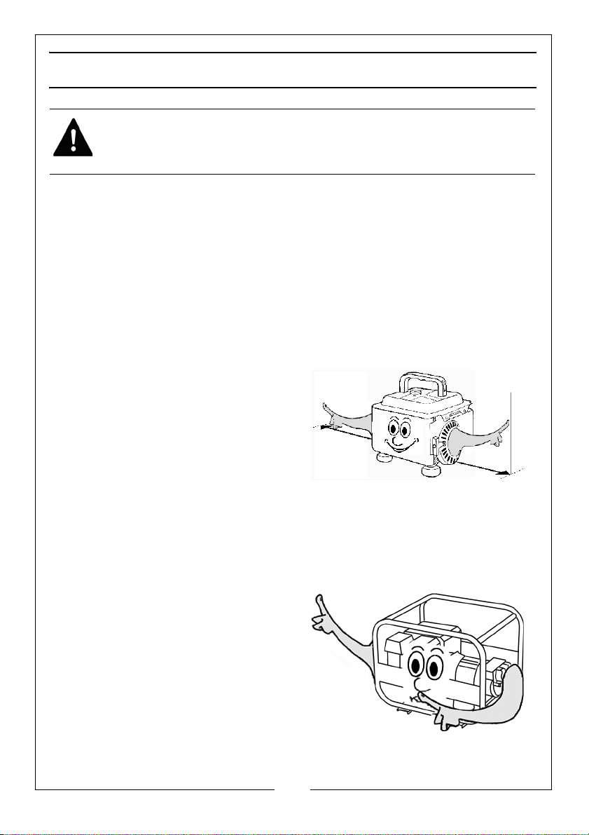
POSITIONING THE GENERATOR
1.
Always leave a least a 1M gap
between the generator and any
rounding building or structures.
sur
2. Always e
a solid, flat surface.
3. Always en
area is free from any material that
could burn or be damaged by
heat.
4. Never move or tilt the generator whilst it is switched on.
nsure the generator is on
sure the surrounding
FIRE PREVENTION
1. Always switch the engine OFF
when refuelling.
2. Always
source of heat.
3. Always refuel in a well ventilated
area.
4. Never over
level specified (See “Checking
the fuel level” on page 10.).
Parts & Service: 020 8988 7400 / E-mail: [email protected] or [email protected]
refuel away from any
fill the tank, fill to the
4
Page 5
5. Never smoke whilst refuelling and avoid smoking or using a naked flame
near the generator.
6. Never
start the engine if there is spilled fuel. Any spillage must be wiped
clean and the generator allowed to dry before attempting to start the
engine.
PREVENTION OF ELECTRIC SHOCK
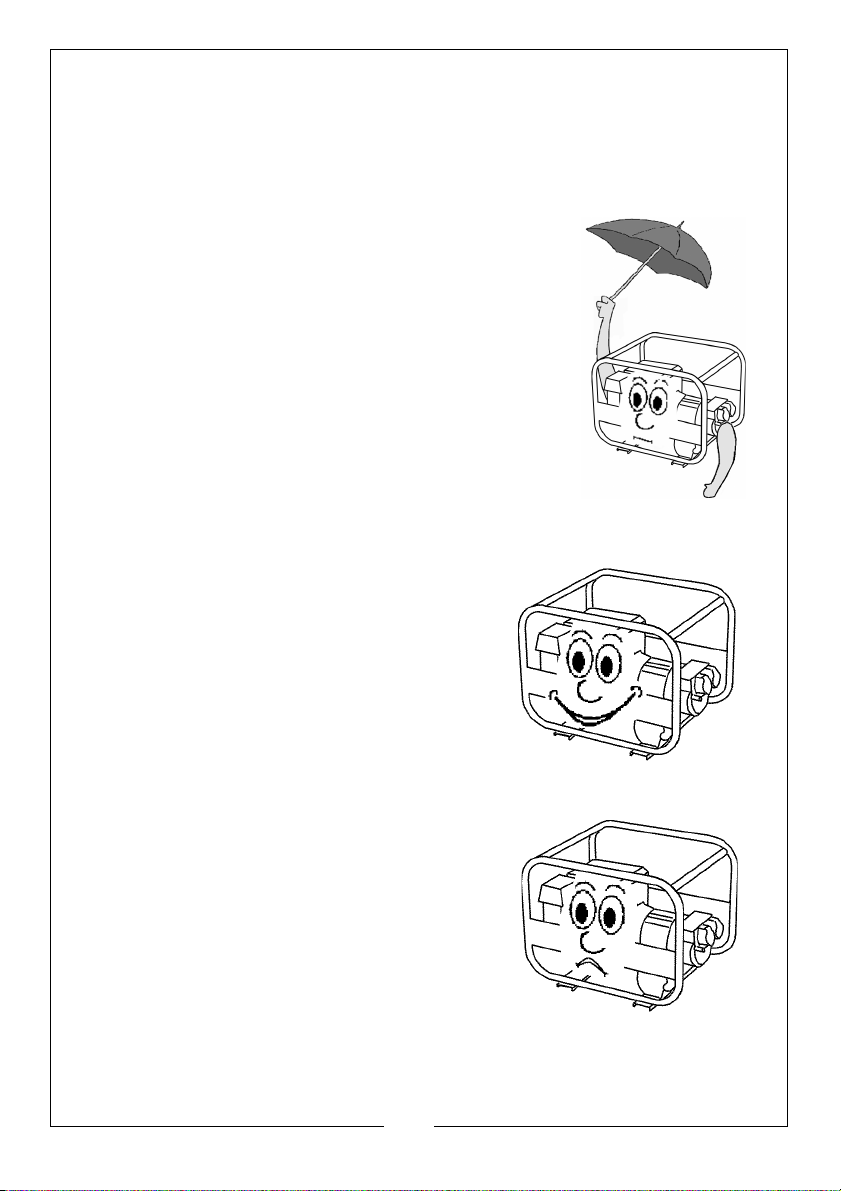
1. NEVER use the generator in wet
conditions unless it is well protected/
covered. Under these conditions,
adequate ventilation MUST be provided.
2. NEVER operate the generator with wet
hands.
3. NEVER use
clean the generator.
4. NEVER allow the gene
become blocked.
water or any other liquids to
rator air vents to
ADDITIONAL SAFETY RULES FOR GENERATORS
1. Always ensure the applied load does
not exceed the generator rating.
Overloading the generator is
dangerous and could cause serious
damage.
2.
Always
carrying out any maintenance.
3. Always ensure the generator reaches
operating speed before connecting a
load.
4.
Never allow the generator to run out of
fuel when a load is connected.
5. Never transport the generator with fuel
in the tank.
6. Do Not
residential power supply; e.g. ring main.
disconnect the generator when
connect to a commercial or
5
Parts & Service: 020 8988 7400 / E-mail: [email protected] or [email protected]
Page 6
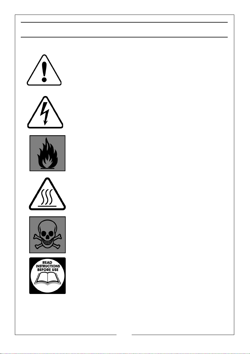
SAFETY SYMBOLS
Caution - The user should be aware of a general hazard
Dangerous Voltage
Flammable
Hot Surface - Do not touch
Poisonous fumes - Do not use the generator in an
enclosed space.
Read Instruction manual before use.
6
Parts & Service: 020 8988 7400 / E-mail: [email protected] or [email protected]
Page 7
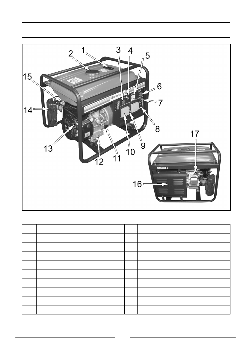
GENERATOR OVERVIEW
NO DESCRIPTION NO DESCRIPTION
1 Fuel level gauge 10 AC plug sockets (2 x 230V)
2 Fuel tank cap 11 Dipstick
3 Engine on/off switch 12 Drain plug
4 Power Indicator 13 Starting handle
5 Voltmeter 14 Air filter
6 AC breaker 15 Fuel supply valve
7 DC reset Button 16 Muffler
8 DC 12V outlet 17 Spark plug
9 Earth Terminal
7
Parts & Service: 020 8988 7400 / E-mail: [email protected] or [email protected]
Page 8

UNPACKING AND ASSEMBLY
Inside the box there should be. The Generator, Spark Plug Box Spanner, Tommy
Bar and 12 Volt DC Battery Charging Lead
If any are missing or have been damaged in transit, speak to your Clarke
dealer immediately.
BEFORE USING THE GENERATOR
IMPORTANT: Generators should ALWAYS be earthed.
Attach a suitable earth lead to a good earth - water pipe, ground spike etc.,
whenever you use this generator.
Before using your generator make sure that the generator is:
• in good condition and not damaged.
• clean and free from fuel or oil spillage.
• correctly located for use (See page 4).
• The fuel system and connectors are intact and there is no leakage.
NOTE: Always use a funnel to fill the fuel tank. If fuel is spilt it must be
cleaned up before you start the engine
WARNING: ENSURE THERE IS ADEQUATE FUEL IN THE TANK WHEN USING
THE GENERATOR. RUNNING OUT OF FUEL OR STOPPING THE ENGINE
SUDDENLY WITH A LOAD CONNECTED COULD CAUSE SERIOUS DAMAGE.
.
EARTH POINT
Always connect the generator to an
earth point. The earth terminal is
shown on the right.
8
Parts & Service: 020 8988 7400 / E-mail: [email protected] or [email protected]
Page 9
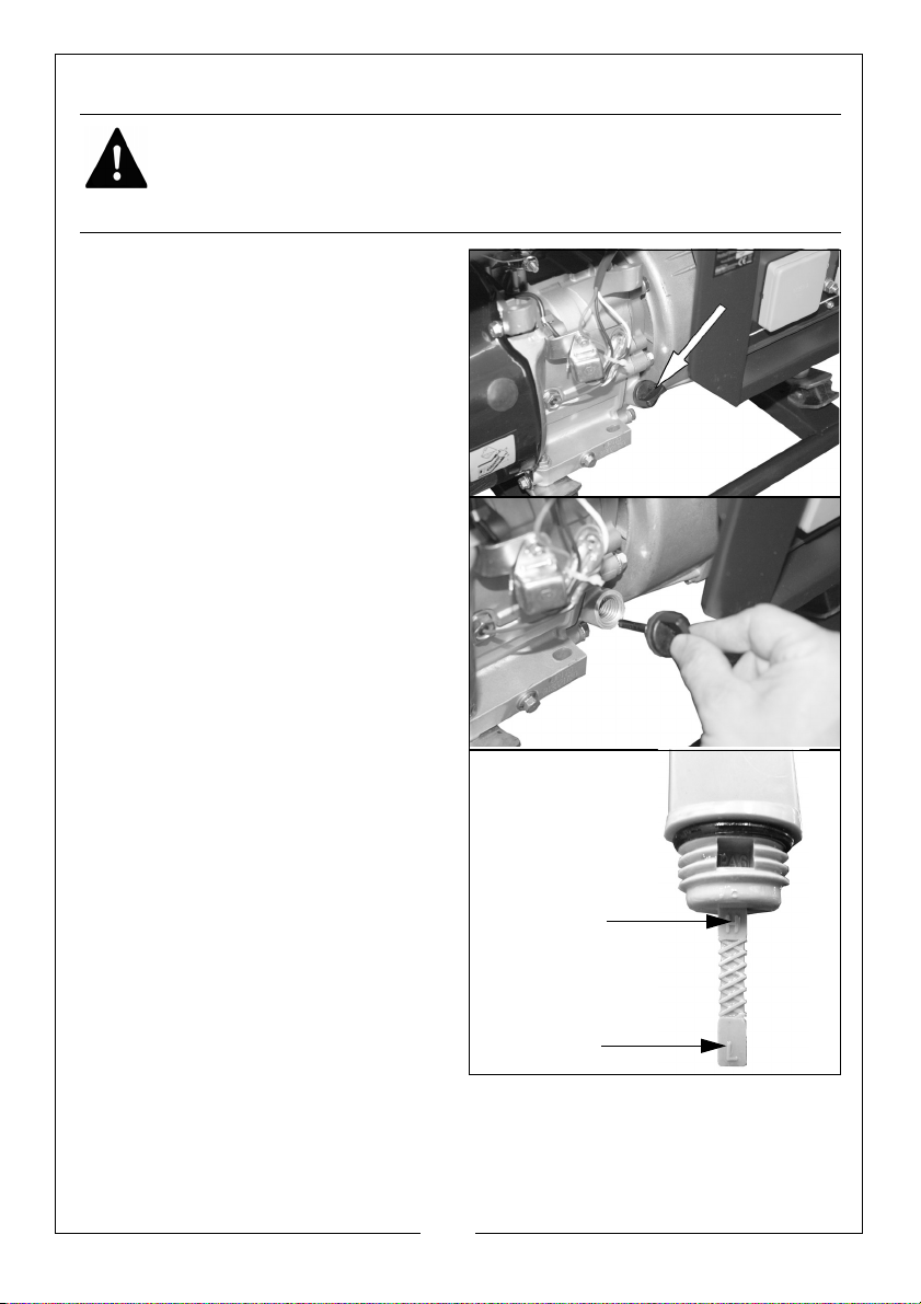
CHECKING THE ENGINE OIL LEVEL
‘H’ Level
‘L’ Level
WARNING: TO CARRY OUT THIS CHECK, PLACE THE GENERATOR ON LEVEL
GROUND WITH THE ENGINE SWITCHED OFF (O).
WARNING: TAKE CARE NOT TO TOUCH ANY HOT PARTS OF THE
GENERATOR WHEN CHECKING THE OIL LEVEL.
1. Turn the oil filler cap
counterclockwise and remove
from the oil tank,
2. Clean the dipstick with a cloth.
3. Put the dipstick back into the oil
filler tube and then remove it
again.
• Do not screw it in when doing
this.
If the oil is below the ‘L’ level on
4.
the dipstick, fill the oil reservoir to
the ‘H’ level on the dipstick.
• Oil Capacity (See
“Spe
cifications” on page 21.)
• We recommend the use of
SAE30 oil in this generator.
5. Replace the oil filler cap.
9
Parts & Service: 020 8988 7400 / E-mail: [email protected] or [email protected]
Page 10
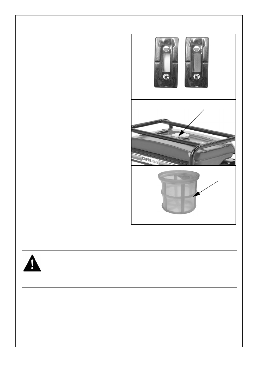
CHECKING THE FUEL LEVEL
Empty
Full
Fuel filler cap
Fuel filter
1. Check the fuel level on the fuel
gauge (located on the top of the
generator).
The fuel gauge will show as red
hen you have fuel in the tank
w
turning white as the fuel level
decreases
2.
To add fuel, remove the fuel filler
cap.
3.
Just inside the fuel tank is a fuel
tank filter, check this filter
periodic
contaminants which may have
accumulated.
4. Slowly add fuel to the fuel tank
(maximum 15L) watching the fuel
level gauge as you do so.
.
ally and remove any
RECOMMENDED FUEL
We recommend the use of standard unleaded petrol.
WARNING: ALWAYS REFUEL IN A WELL VENTILATED AREA AWAY FROM
ANY HEAT SOURCES.
WARNING: ALLOW THE UNIT TO COOL DOWN BEFORE REFUELLING.
WARNING: DO NOT LEAVE FUEL WITHIN THE REACH OF CHILDREN.
NOTE: Do not overfill the fuel tank.
5. Replace the fuel filler cap securely.
10
Parts & Service: 020 8988 7400 / E-mail: [email protected] or [email protected]
Page 11
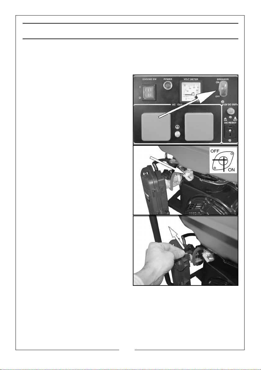
USING YOUR GENERATOR
STARTING THE ENGINE
1. Remove all connections from the AC sockets.
2.
Set the breaker to the off position.
3. Turn the fuel supply valve to the
‘on’ position.
4.
If you are starting the generator
‘cold’, set the choke lever to the
ON position.
warm skip this step.
Parts & Service: 020 8988 7400 / E-mail: [email protected] or [email protected]
If the generator is
11
Page 12
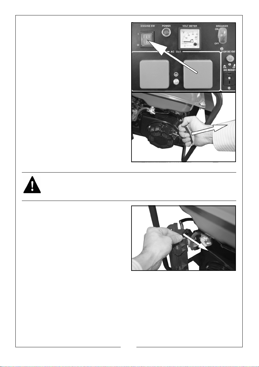
5. Set the engine switch to ‘I’
6. Pull the starting handle lightly until
you start to feel resistance and
then pull up sharply to start the
generator.
NOTE: You may have to do this
more than once.
.
WARNING: ONCE THE GENERATOR HAS STARTED, RELEASE THE STARTING
HANDLE SLOWLY TO AVOID INJURY/DAMAGE AS IT WHIPS BACK.
Once the engine has warmed up,
7.
set the choke lever to the ‘RUN’
position.
12
Parts & Service: 020 8988 7400 / E-mail: [email protected] or [email protected]
Page 13
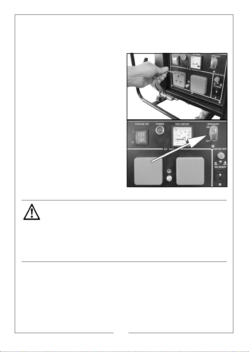
CONNECTING ELECTRICAL DEVICES
The generator can supply both 230V AC and 12V DC.
AC POWER
Start the engine. See page 11.
1.
2. Make sure the appliance is turned
off b
efore connecting it to the
generator.
Set the breaker to ‘ON’.
3.
4. Connect the appliance to the
g
enerator starting with the device
that draws the most current.
CAUTION: MAKE SURE THAT THE APPLIANCE BEING CONNECTED IS IN
GOOD WORKING ORDER, IF IT BEGINS TO ACT ABNORMALLY OR STOPS
SUDDENLY, DISCONNECT IT FROM THE GENERATOR
CAUTION: MAKE SURE THE APPLIANCE DOES NOT EXCEED THE MAXIMUM
RATED LOAD FOR THE GENERATOR.
CAUTION: ANY DEVICE WITH CONTAINS AN INDUCTIVE LOAD E.G.
DEVICES THAT CONTAIN A MOTOR MAY REQUIRED MORE CURRENT ON
STARTUP.
13
Parts & Service: 020 8988 7400 / E-mail: [email protected] or [email protected]
Page 14
DC POWER
(For charging car batteries only.)
CAUTION: MAKE CONNECTIONS TO THE BATTERY AFTER STARTING THE
ENGINE.
1. Start the engine. See page 11.
2.
Connect the battery charging
leads to the battery.
• Clamp the red wire to the
posit
ive (+) terminal and the
black wire to the negative (-)
terminal of the battery. Do not
reverse these positions.
3. Connect the battery charging
ads to the generator.
le
WARNING: TO PREVENT THE POSSIBILITY OF CREATING A SPARK NEAR THE
BATTERY, DISCONNECT THE CABLE TO THE GENERATOR FIRST AND THEN
DISCONNECT THE BATTERY
WARNING: AFTER YOU HAVE CHARGED THE BATTERY, ALWAYS
DISCONNECT THE NEGATIVE LEAD FIRST.
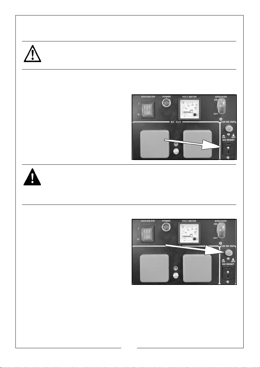
DC OVER LOAD PROTECTOR
If the DC overload protector
activates, wait for a few minutes and
then press the reset button shown on
the right.
14
Parts & Service: 020 8988 7400 / E-mail: [email protected] or [email protected]
Page 15
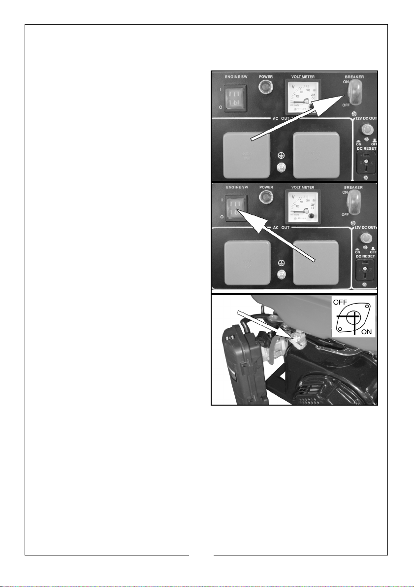
SHUTTING DOWN THE GENERATOR
1. Disconnect all appliances connected to the generator.
2.
Set the breaker to ‘OFF’.
3. Set the engine switch to ‘O’.
4. Set the fuel supply valve to ‘OFF’.
NOTE: T
o stop the generator in an
emergency simply set the
engine switch to ‘O’.
15
Parts & Service: 020 8988 7400 / E-mail: [email protected] or [email protected]
Page 16

MAINTENANCE
CHANGING THE ENGINE OIL
CAUTION: PROLONGED EXPOSURE TO USED ENGINE OIL IS DANGEROUS,
ALWAYS WASH YOUR HANDS THOROUGHLY AFTER HANDLING USED
ENGINE OIL.
1. Unscrew and remove the oil filler cap/dipstick.
2. Place a oil collection tray under the drain plug.
3. Unscrew the drain plug, and allow the used engine oil to drain from the
crankcase into the oil collection tray.
NOTE: Drain the engine oil when the engine is warm, this will ensure the
oil flows out quicker.
4. Replace the drain plug and its seal ring.
5. Fill the crankcase with engine oil to the ‘H’ mark on the dipstick. See
page 9.
6. Replace the oil filler cap/dipstick.
ENVIRONMENTAL PROTECTION
One of the most damaging sources of pollution is oil, do not throw away used
engine oil in with your domestic trash or down drains and sinks. Place it in a
leak proof container and take it to your local waste disposal site.
16
Parts & Service: 020 8988 7400 / E-mail: [email protected] or [email protected]
Page 17
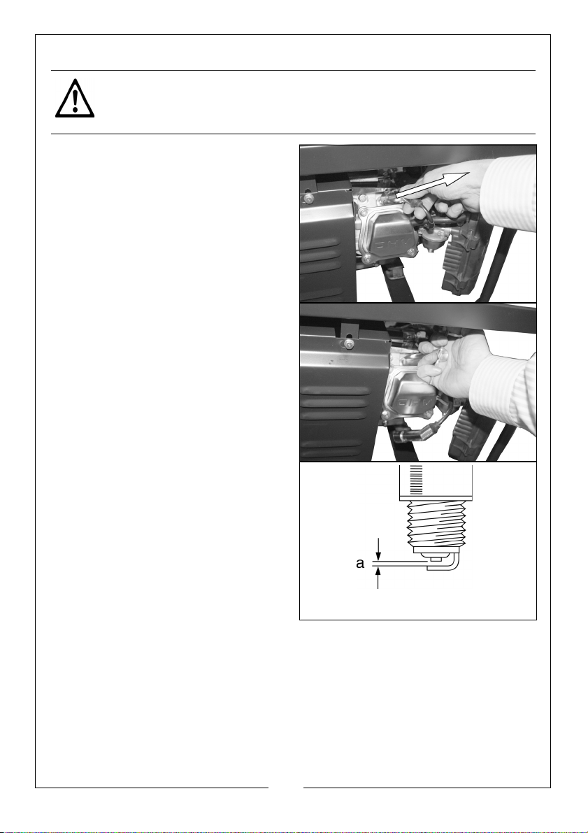
CHANGING THE SPARK PLUG
Add pic
CAUTION: ALLOW THE ENGINE TO COOL BEFORE REMOVING THE SPARK
PLUG.
1. Remove the spark plug cap from
the spark plug.
2.
Use the supplied spark plug
spanner to remove the spark plug.
3. Remove any carbon that has
ac
cumulated around the
sparkplug.
Check the spark plug gap (a), it
4.
should be between 0.7 and 0.8
mm, adjust if necessary.
5. Check the overall condition of the
spa
rk plug and replace if
necessary.
6. Reinstall the spark plug and
replace the spark plug cap.
17
Parts & Service: 020 8988 7400 / E-mail: [email protected] or [email protected]
Page 18
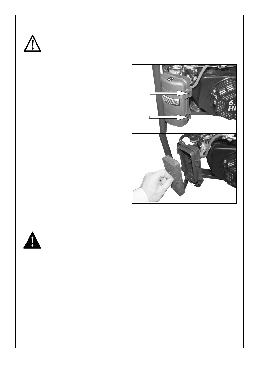
CHECKING THE AIR FILTER
CAUTION: DO NOT USE THE GENERATOR WITHOUT THE AIR FILTER FITTED,
THIS CAN DAMAGE THE GENERATOR.
1. Unlock and remove the air filter
cover.
2. Remove the air filter element.
3. Make sure that the air filter is
clean and not
• If the air filter is damaged
co
ntact Clarke spare parts
department for a replacement.
• If the filter is dirty, wash the filter
in a solution of warm water and
mild detergent and rinse
thoroughly. Leave the filter to
dry completely, once it is dry immerse the filter in clean engine oil
and squeeze the filter to remove excess oil.
damaged.
WARNING: DO NOT USE INFLAMMABLE SOLVENTS OR PETROL TO CLEAN
THE AIR FILTER.
4. Replace the filter back into its original position an
d replace the air filter
cover.
18
Parts & Service: 020 8988 7400 / E-mail: [email protected] or [email protected]
Page 19
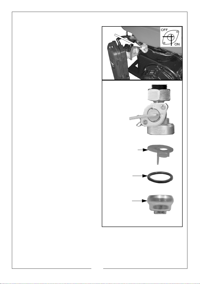
CLEANING THE FUEL VALVE FILTER / DRAINING THE FUEL TANK
Add pic
VALVE FILTER
‘O’ RING
CUP
1. Set the fuel supply valve to OFF.
2. U
nscrew and remove the cup,
then remove the valve filter and
g.
‘O’ rin
3. Wash these parts in a nonflammable solvent. Mak
that the valve filter is not
damaged.
4. Place an approved petrol storage
container under the fuel valve
and set the fuel supply valve to
‘ON’.
• The fuel in the tank will drain
into the container.
5. Replace the ‘O’ ring and valve
filter and
possible.
tighten the cup as far as
e sure
19
Parts & Service: 020 8988 7400 / E-mail: [email protected] or [email protected]
Page 20
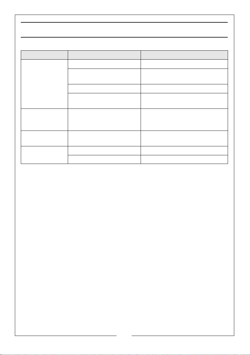
TROUBLESHOOTING
PROBLEM CAUSE SOLUTION
The generator
start
fails to
The generator
o generate
fails t
electricity
The generator is
difficult to start
If this does not solve your problem, please contact the Clarke service
depart
ment.
Engine switch is off Set the engine switch to ‘I’
Not enough oil in the
rator
gene
No fuel Add more fuel, See page 10
Spark plugs not working
correctly
The device you are trying
to power is faulty
The AC breaker is switched
off
The air filter is dirty Clean the air filter, See page 18
The fuel filter is dirty Clean the fuel filter, See page 19
Add more oil, See page 9
Change the spark plugs, See
page 17
Make sure the device you want
to power is working properly
Switch the AC breaker on
20
Parts & Service: 020 8988 7400 / E-mail: [email protected] or [email protected]
Page 21
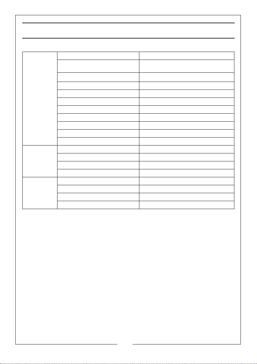
SPECIFICATIONS
Engine Engine Model UP170
Type Petrol air cooled 4-Stroke OHV single
3
Displacement (cm
Max. power output (HP/rpm) 7.0 / 3600
Ignition type Magneto
Start system Recoil
Fuel tank capacity (L) 15
Fuel consumption (L/h) 1.4
Duration of run (h) 11
Engine oil capacity (L) 0.6
Guaranteed sound power (L
Generator Rated Frequency (Hz) 50
Rated Voltage (V) 230
Rated Power (kVA) 2.6
Max. Power (kVA) 2.8
Dimensions Length (mm) 592
Width (mm) 498
Height (mm) 432
Unpacked Weight (kg) 45
)
WA dB) 96
cyl
208
inder
21
Parts & Service: 020 8988 7400 / E-mail: [email protected] or [email protected]
Page 22
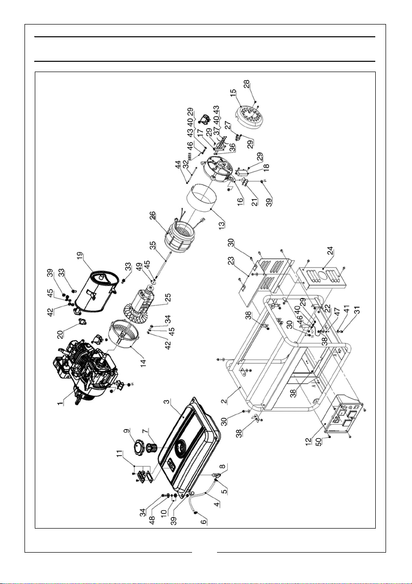
EXPLODED PARTS DIAGRAM
22
Parts & Service: 020 8988 7400 / E-mail: [email protected] or [email protected]
Page 23
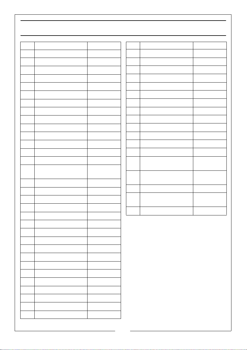
PARTS LIST
NO DESCRIPTION PAR T N O
1 UP170‐41Engine RKFG300501
2 Frame RKFG300502
3 FuelTa
4 Φ4.
5 Φ8Cl
6 Φ7Cl
7 FuelTa
8 FuelSw
9 FuelTa
10 ShockAbsorption RKFG300510
11 FuelMark
12 ControlP
13 AlternatorGuar
14 190Fr
15 190Re
16 190Re
17 WireFa
18 AVR RKFG300518
19 Muffler RKFG300519
20 MuflerGa
21 ShockAbsorption RKFG300521
22 GroundingWi
23 MufflerSideGu
24 MufflerOu
25 Rotor RKFG300525
26 Stator RKFG300526
27 CarbonBr
28 FlangeBo
29 FlangeBo
30 FlangeBo
31 FlangeBo
32 BoltM6
nk RKFG300503
5mmFuelPipe RKFG300504
amp RKFG300505
amp RKFG300506
nk Filter RKFG300507
itch RKFG300508
nk Cap RKFG300509
erAssembly RKFG300511
annel RKFG300512
dBoard RKFG300513
ontEndCover RKFG300514
arEndCover
Guard
arEndCover RKFG300516
stenConnection RKFG300517
sket RKFG300520
re RKFG300522
ard RKFG300523
tsideGuard RKFG300524
ush RKFG300527
ltM5x12 RKFG300528
ltM5x16 RKFG300529
ltM6x12 RKFG300530
ltM6x14 RKFG300531
x130 RKFG300532
RKFG300515
NO DESCRIPTION PART NO
33 FlangeBo
34 BoltM8x
35 Bolt5/
36 Full‐thr
37 NutM5 RKFG300537
38 FlangeNutM6 RKFG300538
39 FlangeNutM8 RKFG300539
40 FlatWa
41 FlatWa
42 FlatWa
43 SpringWa
44 SpringWa
45 SpringWa
46 ExternalT
WasherΦ5
47 ExternalT
WasherΦ6
48 FlatWa
49 LargeFla
Φ8(H=3)
50 ScrewM6x1
ltM8x20 RKFG300533
25 RKFG300534
1 6 ‐210 RKFG300535
eadBoltM5x20 RKFG300536
sherΦ5 RKFG300540
sherΦ6 RKFG300541
sherΦ8 RKFG300542
sherΦ5 RKFG300543
sherΦ6 RKFG300544
sherΦ8 RKFG300545
oothLock
oothLock
sherΦ8 RKFG300548
tWasher
2 RKFG300550
RKFG300546
RKFG300547
RKFG300549
23
Parts & Service: 020 8988 7400 / E-mail: [email protected] or [email protected]
Page 24
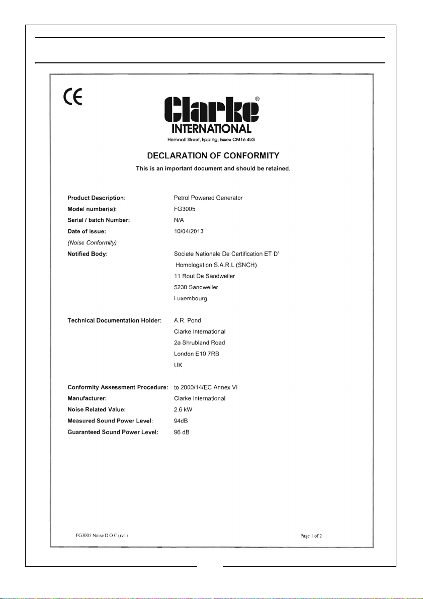
DECLARATION OF CONFORMITY
24
Parts & Service: 020 8988 7400 / E-mail: [email protected] or [email protected]
Page 25
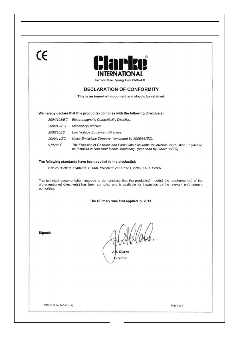
DECLARATION OF CONFORMITY
25
Parts & Service: 020 8988 7400 / E-mail: [email protected] or [email protected]
Page 26

Page 27

Page 28

 Loading...