

Page 1
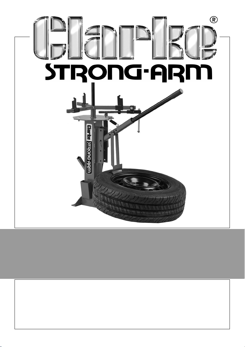
MANUAL TYRE CHANGER
MODEL NO: CMTC1
PART NO: 7640280
ASSEMBLY & USER INSTRUCTIONS
ORIGINAL INSTRUCTIONS GC1019 - ISS 2
Page 2
INTRODUCTION
Thank you for purchasing this CLARKE Manual Tyre Changer.
Before attempting to operate the product, it is essential that you read this
manual thoroughly and carefully follow all instructions given. In doing so you
will ensure the safety of yourself and that of others around you, and you can
also look forward to the stand giving you long and satisfactory service.
FLOOR MOUNTING BEFORE USE
It is essential that the tyre changer is bolted firmly to either the workshop floor
or a suitable working base using the pre-drilled holes in the base.
Holding-down (10mm expansion type) bolts will be required for fixing to a
concrete floor as a semi-permanent installation.
TECHNICAL SPECIFICATIONS
Weight 27 kg
Dimensions (L x W x H) 460 x 600 x 860 mm
Min/max wheel rim diameter 4 - 21”
Suitable wheel types
IMPORTANT
May be unsuitable for aluminium or
magnesium alloy wheels or carbonfibre wheels due to risk of damaging
the rims.
The tool is unsuitable for motorcycle
wheels and other wheels that do not
have open centres.
GUARANTEE
This CLARKE product is guaranteed against faulty manufacture for a period of
12 months from the date of purchase. Please keep your receipt as proof of
purchase.
This guarantee is invalid if the product is found to have been abused or
tampered with in any way, or not used for the purpose for which it was
intended.
Faulty goods should be returned to their place of purchase, no product can
be returned to us without prior permission.
This guarantee does not effect your statutory rights.
2
Parts & Service: 020 8988 7400 / E-mail: [email protected] or [email protected]
Page 3

SAFETY PRECAUTIONS
1. The tyre changer should be bolted firmly to the workshop floor using the
pre-drilled holes in the base plate before use.
2. Do not allow personnel to use the tyre changer unless they have read
these safety precautions.
3. Never tamper with the product or modify it in any way, as this could prove
to be dangerous and will invalidate the guarantee. Only use the product
for the purpose for which it is intended.
4. Ensure that the tyre changer is in good working order. Have any damaged
parts repaired or replaced immediately. Use genuine Clarke parts only. The
use of unauthorised parts may be dangerous and invalidate the
guarantee.
5. Do not use the tyre changer if it is damaged.
6. Always use the tyre changer in a suitable, well lit work area.
7. Keep the work area clean and tidy and free from unrelated items.
8. Do not use the tyre changer when you are tired or under the influence of
alcohol, drugs or intoxicating medication.
9. Ensure all bystanders keep at a safe distance whilst the tyre changer is in
use.
10. Never climb on the tyre changer.
11. Take care not to trap your fingers in the adjustable parts.
12. Do not over-reach. Keep your proper footing and balance at all times.
13. Safety equipment such as gloves and non-skid shoes will reduce personal
injuries.
14. Failure to heed these warnings may result in damage to the equipment, or
serious personal injury.
15. Always visually inspect the tyre changer before use, to ensure that all parts
are correctly located and secure. Check for cracks, deformation or other
signs of damage or worn parts.
UNPACKING PRIOR TO ASSEMBLY
Unpack the components on a clean flat area of hard standing and ensure
that all parts are present. Identify all components according to the illustration.
Open or ring spanners (17 mm) or an adjustable wrench will be required for
assembly.
3
Parts & Service: 020 8988 7400 / E-mail: [email protected] or [email protected]
Page 4
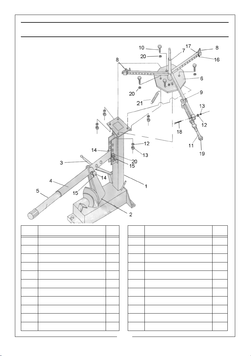
INVENTORY
NO DESCRIPTION QTY NO DESCRIPTION QTY
1 Base assembly 1 12 Spring washer 4
2 Breaker shoe 1 13 Nut 5
3 Tyre lever 1 14 Large clevis pin 2
4 Breaker arm 1 15 Large R-clip 2
5 Handle extension 1 16 Small clevis pin 2
6 Top plate assembly 1 17 Small R-clip 2
7 Centre pedestal 1 18 Long bolt 1
8 Loose wheel clamp 2 19 Locknut 2
9 Clamp assembly 1 20 Flat washer 6
10 Bolt 17mm 4 21 Tension spring 1
11 Clamp handle 1
4
Parts & Service: 020 8988 7400 / E-mail: [email protected] or [email protected]
Page 5
ASSEMBLY AND FLOOR MOUNTING
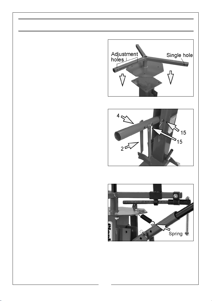
1. Mount the tyre changer base
assembly rigidly as described on
page 2.
2. Using four bolts (10), spring
washers (12), flat washers (20) and
nuts (13), attach the top plate
assembly (6) to the base assembly
(1).
NOTE: The arm with the single hole
should be positioned closest
to the operator.
3. Fit the breaker arm (4) into the
bracket using the large clevis pin
(14), washer (20) and large R-clip
(15).
NOTE: The position can be
changed according to the
size of the tyre by moving the
clevis pin to a different hole.
(see page 6).
4. Add the breaker shoe (2) to the
arm (4) using the other large clevis pin (14), washer (20) and large R-clip
(15).
5. When setting the breaker arm in
the higher positions the supporting
spring (21) can be used by
connecting it to the top plate and
the arm.
5
Parts & Service: 020 8988 7400 / E-mail: [email protected] or [email protected]
Page 6
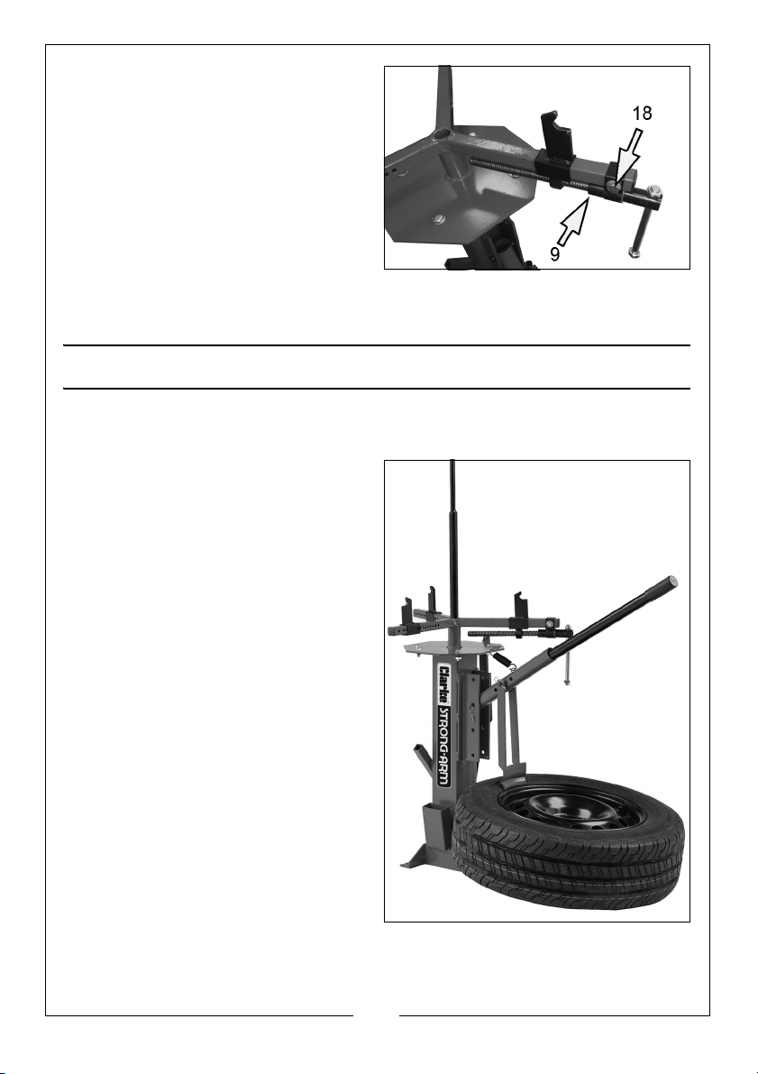
6. Slide the clamp assembly (9) onto
the front arm of the top plate
assembly & secure with the long
bolt (18), washer (20) & nut(13).
7. Add the loose wheel clamps
which are set in position using the
small clevis pins (16) and r-clips
(17). See note on page 7.
8. Add the centre pedestal (7) to
the top assembly.
9. When ready to use, slide the handle (5) into the breaker arm. At other
times it can be stored in the socket on the side of the base assembly.
OPERATION
BREAKING THE TYRE BEAD SEAL
1. Deflate the tyre and remove any
balance weights from the wheel
rim before breaking the bead
seal.
• The use of a rubber lubricant will
make removal and remounting of
the tyre much easier. (lubricant not
supplied)
2. To break the tyre bead loose from
the wheel rim, lay the tyre on the
base plate against the triangular
stop to keep the tyre from sliding.
3. Set the breaker shoe on the tyre
against the rim.
• When working with different sizes of
tyre you will need to use different
holes in the arm bracket to adjust
the breaker shoe position.
4. Adjust the shoe height by
removing the clevis pin and
moving the shoe up or down.
5. Insert the end of the handle into the breaker arm and push down causing
the breaker shoe to force the tyre bead off the wheel rim. If the bead does
not separate all around, turn the tyre and repeat in different locations.
6
Parts & Service: 020 8988 7400 / E-mail: [email protected] or [email protected]
Page 7
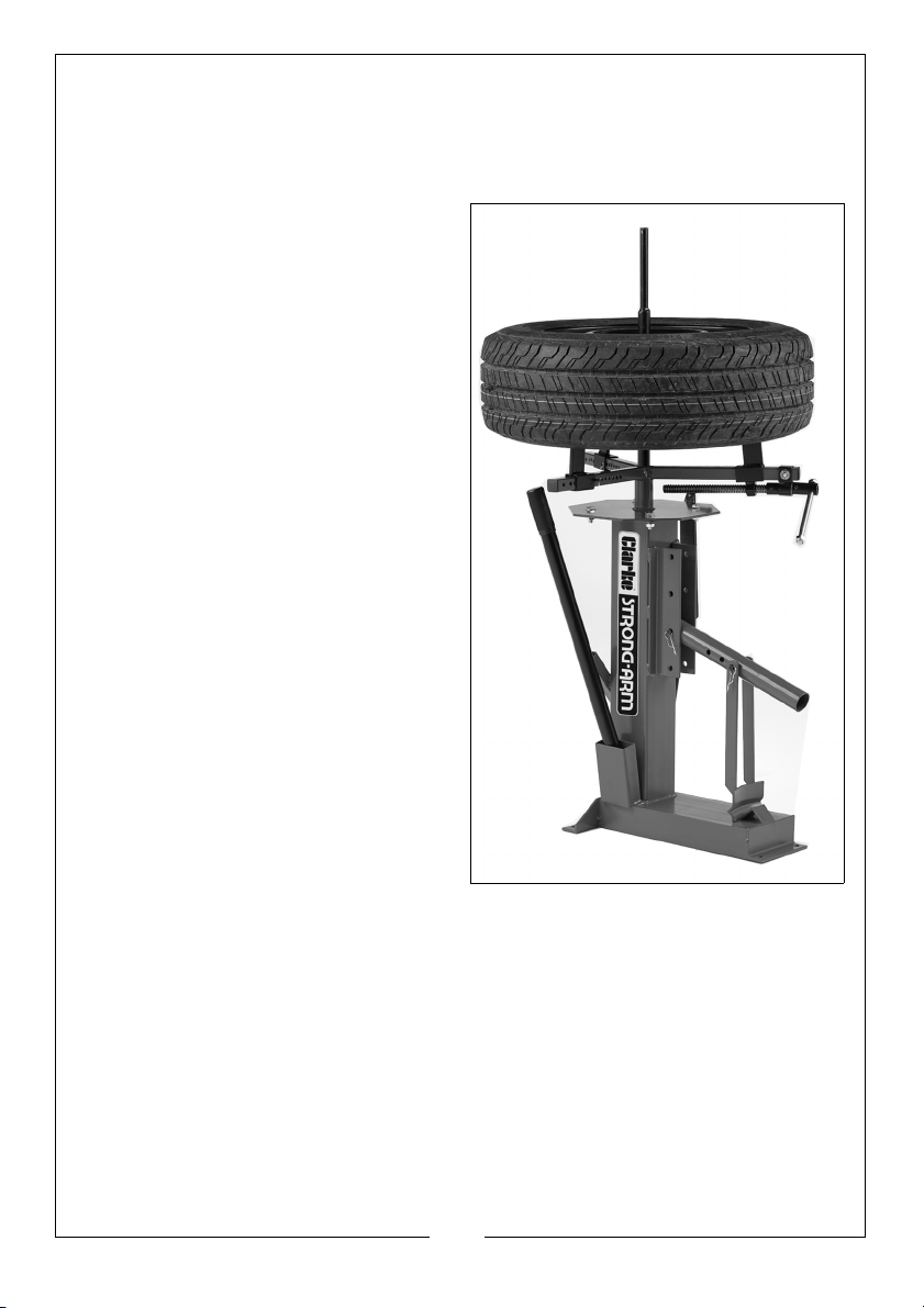
MOUNTING AND DEMOUNTING TYRES
TYRE REMOVAL
1. After the bead seal is broken, place the tyre over the centre pedestal.
2. Clamp the wheel rim between the
wheel clamps and tighten using
the clamp handle. Take care not
to damage the rim of the wheel
by overtightening.
NOTE: The clamps can be installed
with the upstands located
on the inside or outside. The
outside position is usually the
best and most secure
position, thereby gripping
the wheel towards the
centre.
3. With the tyre held securely, insert
the flat end of the tyre lever (3)
between the tyre and the wheel
rim. Pull the lever toward you
across the tyre to force the bead
off the rim.
• Some lubrication with soap & water
around the edge of the rim and tyre
will help the process.
4. Work the bar all the way round
the centre pedestal to
completely dismount the tyre.
5. Pull the bottom bead upwards
and place the flat end of the tyre
lever between the tyre and the lower rim as before and repeat to
completely remove the tyre.
TYRE FITTING
1. To mount a tyre, again lubricate both beads of the tyre and place the tyre
on top of the wheel.
2. With the lower bead sitting on the rim, push the tyre forward and down and
hook the end of the tyre lever over the edge of the rim.
3. Press down on the tyre to hold it below the rim and with the other hand,
pull the lever anti-clockwise around the centre pedestal until the bead slips
over the rim. Repeat with the other tyre bead.
7
Parts & Service: 020 8988 7400 / E-mail: [email protected] or [email protected]
Page 8

 Loading...