

Page 1
WORKBENCH
MODEL NO: CWB300
Part No: 7637872
ASSEMBLY INSTRUCTIONS
GC0416
Page 2
INTRODUCTION
Thank you for purchasing this CLARKE workbench.
Before attempting to use this product, please read this manual thoroughly and
follow the instructions carefully. In doing so you will ensure the safety of yourself
and that of others around you, and you can look forward to your purchase
giving you long and satisfactory service.
SPECIFICATION
Model CWB300
Dimensions (L x W x H) 1500 x 750 x 895 mm
Weight 21.7 kg
Maximum rated load 300 kg
GUARANTEE
This CLARKE product is guaranteed against faulty manufacture for a period of
12 months from the date of purchase. Please keep your receipt as proof of
purchase.
This guarantee is invalid if the product is found to have been abused or
tampered with in any way, or not used for its intended purpose.
Faulty goods should be returned to their place of purchase, no product can
be returned to us without prior permission.
This guarantee does not effect your statutory rights.
2
Parts & Service: 020 8988 7400 / E-mail: [email protected] or [email protected]
Page 3

SAFETY PRECAUTIONS
1. Always read these instructions before use.
2. Always wear protective gloves when assembling the workbench.
3. It is recommended that the assembly be done by two persons.
4. Not following these instructions could result in the workbench falling over,
causing damage to equipment and personal injury.
5. Never carry out any alterations or modifications to this product or use the
workbench for a purpose for which it was not intended.
6. Never allow children to climb on the workbench.
7. Always ensure the load is positioned centrally and evenly distributed.
8. If replacing parts, only use those supplied by Clarke International.
9. Do not exceed the maximum rated load of 300kg as shown on the warning
label.
10. Only use on a flat, level surface capable of supporting the workbench and
its maximum load.
11. Always ensure you are working on a firm flat surface, and that the
workbench is completely stable.
12. Take care when placing a heavy load on to the bench. It should be
placed gently so that the strain is taken up gradually.
13. Always keep the work areas clean and well lit.
14. Check for damaged parts before using the workbench. Any part that
appears damaged should be carefully checked to determine that it will
perform its intended function. Replace any damaged parts as soon as
possible.
15. Keep these instructions in a safe place for future reference.
3
Parts & Service: 020 8988 7400 / E-mail: [email protected] or [email protected]
Page 4
UNPACKING & INVENTORY
When unpacking, check for damaged or missing parts. Any deficiencies
found should be reported to your CLARKE dealer where the product was
originally purchased.
Do not dispose of damaged components or packaging with general
household waste. They should be taken to a recycling centre and disposed of
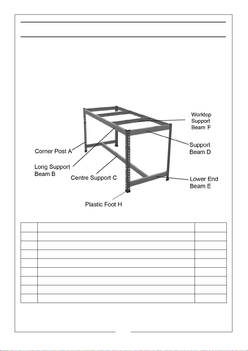
appropriately. This product should include the following;
:
No Description Quantity
ACorner Post 4
B Long Support Beam 2
C Centre Support 1
D Short Support Beam 2
ELower End Beam 2
F Worktop Support Beam 2
G Worktop Panel (see front cover picture) 1
H Plastic Foot 4
4
Parts & Service: 020 8988 7400 / E-mail: [email protected] or [email protected]
Page 5

ASSEMBLY
TOOLS REQUIRED
• Rubber mallet or hammer
• Protective cloth/wood block
ASSEMBLY INSTRUCTIONS
1. Assemble on a firm, level surface. Avoid assembly on a domestic carpet.
2. Always ensure that the tabs sit at the bottom of the slots.
3. It is recommended that the assembly should be done by two persons.
4. Use a cloth or softwood block to
protect the surface finish of the
product when using a mallet.
5. The tabs of the beams will often
enter the slots fully using just firm
hand pressure but if they are too
tight, you may require a rubber
mallet to assist. If so, always use a
cloth to protect the product paint
finish.
6. Tap gently with the mallet to drive the tabs of the beams fully into the slots
in the corner post. Always strike the edge close to the post.
7. Decide how high you want the lower beams to be, relative to the floor,
noting that the lower beams should never be more than half height from
the bottom of the corner posts.
8. Use the short support beams (D) to
connect the front and rear corner
posts (A) together. Ensure the
support beam (D) is in the highest
possible position.
NOTE: The beam edge with the
wider flange should be
installed uppermost to
support the worktop.
9. Add the lower end beam (E) with
the two connecting slots). Repeat this again for the other end assembly,
making sure that the corresponding lower end beams are at the same
height.
5
Parts & Service: 020 8988 7400 / E-mail: [email protected] or [email protected]
Page 6
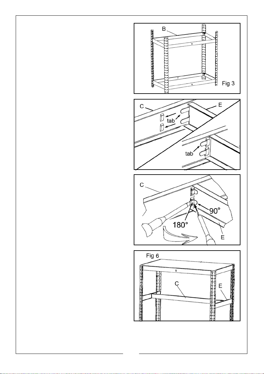
10. Use the long support beams (B) to
connect the two end assemblies
together as shown in Fig 3.
11. Add the worktop support beam
(F), by bending the flexible tabs to
90 degrees and slotting them into
place as shown in Fig 4.
12. Finally bend the tabs back 180
degrees to lock securely as shown
in Fig 5.
13. Connect the centre support (C)
to the lower end beams (E) by
bending the flexible tabs to 90
degrees and slotting them into
place as shown in Fig 6. Finally
bend the tabs back 180 degrees
to lock in place.
6
Parts & Service: 020 8988 7400 / E-mail: [email protected] or [email protected]
Page 7
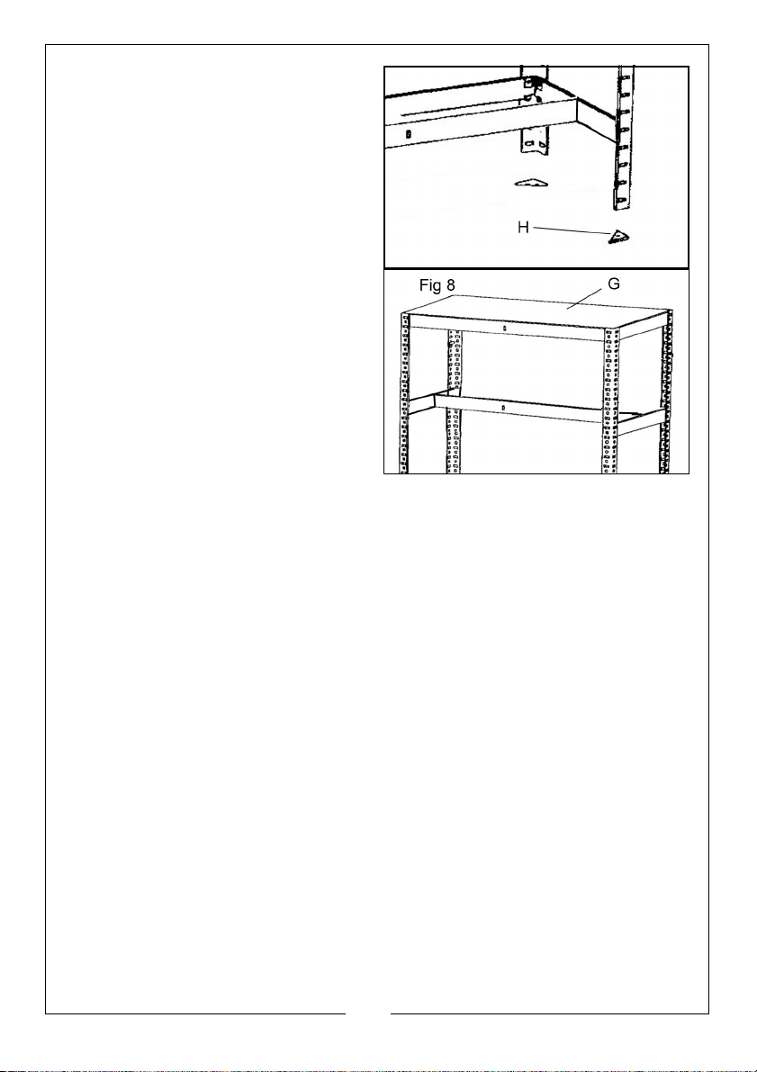
14. Fit the bench onto the plastic feet.
15. Lay the worktop panel (G) into
position on the support beams.
• Always fit the worktop at the
highest possible position.
SPARE PARTS
In the event of damage, spare parts are available from the Clarke
International parts department.
7
Parts & Service: 020 8988 7400 / E-mail: [email protected] or [email protected]
Page 8

 Loading...