

Page 1
CUMB1 - Universal Mobile Base.fm Page 1 Thursday, June 20, 2013 10:35 AM
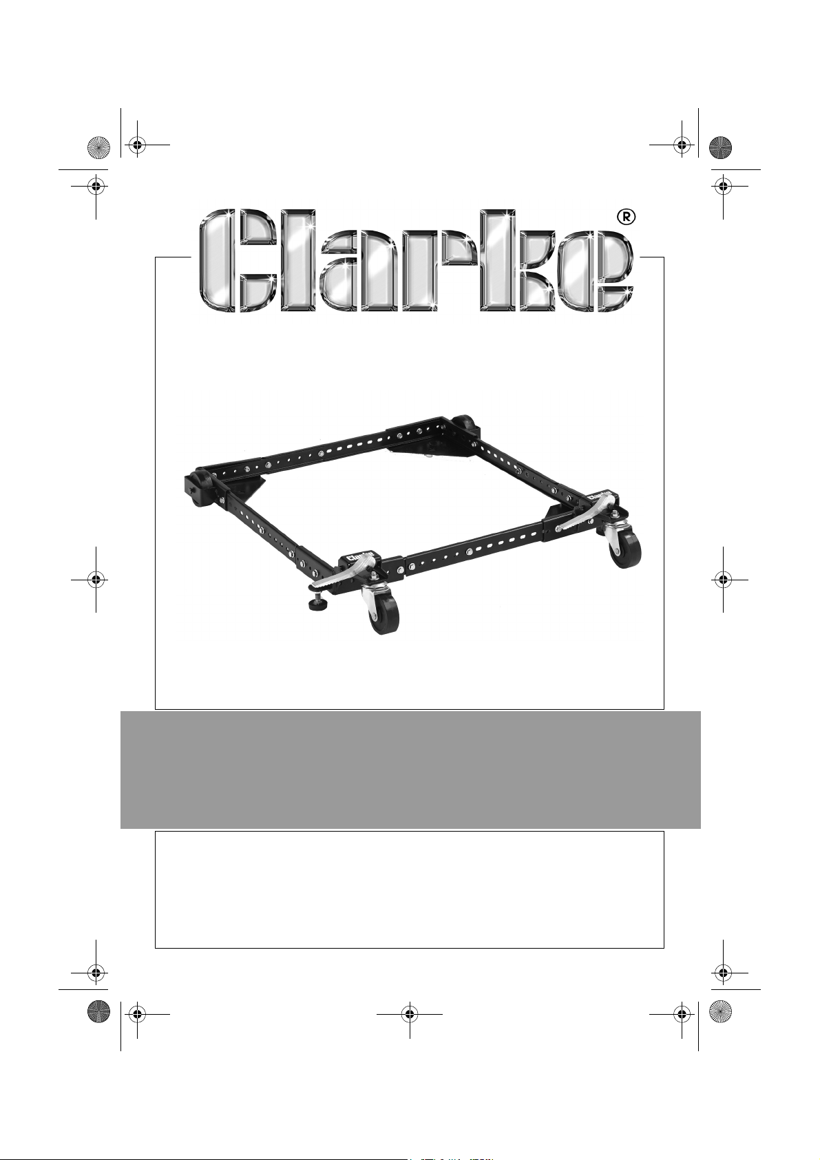
UNIVERSAL MOBILE BASE
MODEL NO: CUMB1
PART NO: 7630211
ASSEMBLY & OPERATING
INSTRUCTIONS
LS0613
Page 2
CUMB1 - Universal Mobile Base.fm Page 2 Thursday, June 20, 2013 10:35 AM
INTRODUCTION
Thank you for purchasing this CLARKE Universal Mobile Base.
Before attempting to use this product, please read this manual thoroughly and
follow the instructions carefully. In doing so you will ensure the safety of yourself
and that of others around you, and you can look forward to your purchase
giving you long and satisfactory service.
GUARANTEE
This product is guaranteed against faulty manufacture for a period of 12
months from the date of purchase. Please keep your receipt which will be
required as proof of purchase.
This guarantee is invalid if the product is found to have been abused or
tampered with in any way, or not used for the purpose for which it was
intended.
Faulty goods should be returned to their place of purchase, no product can
be returned to us without prior permission.
This guarantee does not effect your statutory rights.
IN THE CARTON
Unpack and identify all components and hardware. Make sure there are no
missing parts and that there is no shipping damage.
Qty Description Qty Description
4 Long Side Rails 25 ½” Bolt
4 Short Side Rails 25 Small Flange Nut
2 Castor Plate 2 Large Nut
2 Castor Corner Bracket 2 Large Flange Nut
2 Fixed Wheel Corner Bracket 2 2½” Cam Pivot Bolt
2 Cam Lever 6 Self-locking Nut
2 Adjustable Foot 2 Pivot Rod Bolt
2 Castor 2 1¾” Wheel Axle Bolt
2 Wheel
2
Parts & Service: 020 8988 7400 / E-mail: [email protected] or [email protected]
Page 3
CUMB1 - Universal Mobile Base.fm Page 3 Thursday, June 20, 2013 10:35 AM
SAFETY INSTRUCTIONS FOR MOBILE BASES
1. Place the mobile base on a level surface and adjust the feet before
placing the machine in position. This should stop the machine rocking,
while testing it for stability. Test for stability in both the up (on the castors)
and the down positions.
2. Take extra care when testing the stability of top heavy machines.
3. Unplug any power tool before moving or repositioning the mobile base.
4. Always check stability for safety after repositioning.
5. Care should be taken when planning the orientation of the machine on
the universal mobile base. When the weight is on the castors the machine
will tilt 1/2'' toward the fixed wheels.
6. Never use your machine while it is supported on the two swivel castors.
Always lower the machine onto the adjustable feet before use.
7. When moving the base, always push the base, not the machine. take care
not to tilt the machine over when moving.
8. SECURE ALL FASTENERS - Make sure that all nuts & bolts on the mobile base
are fully tightened before use.
9. RATED WEIGHT LIMIT - Do not install machines exceeding the rated weight
capacity of the mobile base. (See Page 7)
10. APPROPRIATE LOCATION FOR USE - Use only on flat, smooth, sturdy surfaces,
that are free of debris and able to support the weight of the machine and
the operator.
11. DISENGAGE CAM LEVERS - Verify that all cam levers are disengaged and
the based is being supported on the adjustabler feet before turning on
your machine. Failure to ensure that your machine is completely immobile
may cause serious injury if the machine begins to move across the floor
during use.
12. BEFORE YOU MOVE THE MACHINE - Ensure that there is a clear path to the
destination. Avoid rolling over any power cords or debris, clutter or
obstructions.
13. DO NOT OVERLOAD - The mobile base is designed to roll smoothly when
operating within its rated weight capacity and requires only steady
pressure to move around. If you find that excessive force is needed, STOP
and check for obstructions or damage to the wheels before proceeding.
3
Parts & Service: 020 8988 7400 / E-mail: [email protected] or [email protected]
Page 4
CUMB1 - Universal Mobile Base.fm Page 4 Thursday, June 20, 2013 10:35 AM
ASSEMBLY INSTRUCTIONS
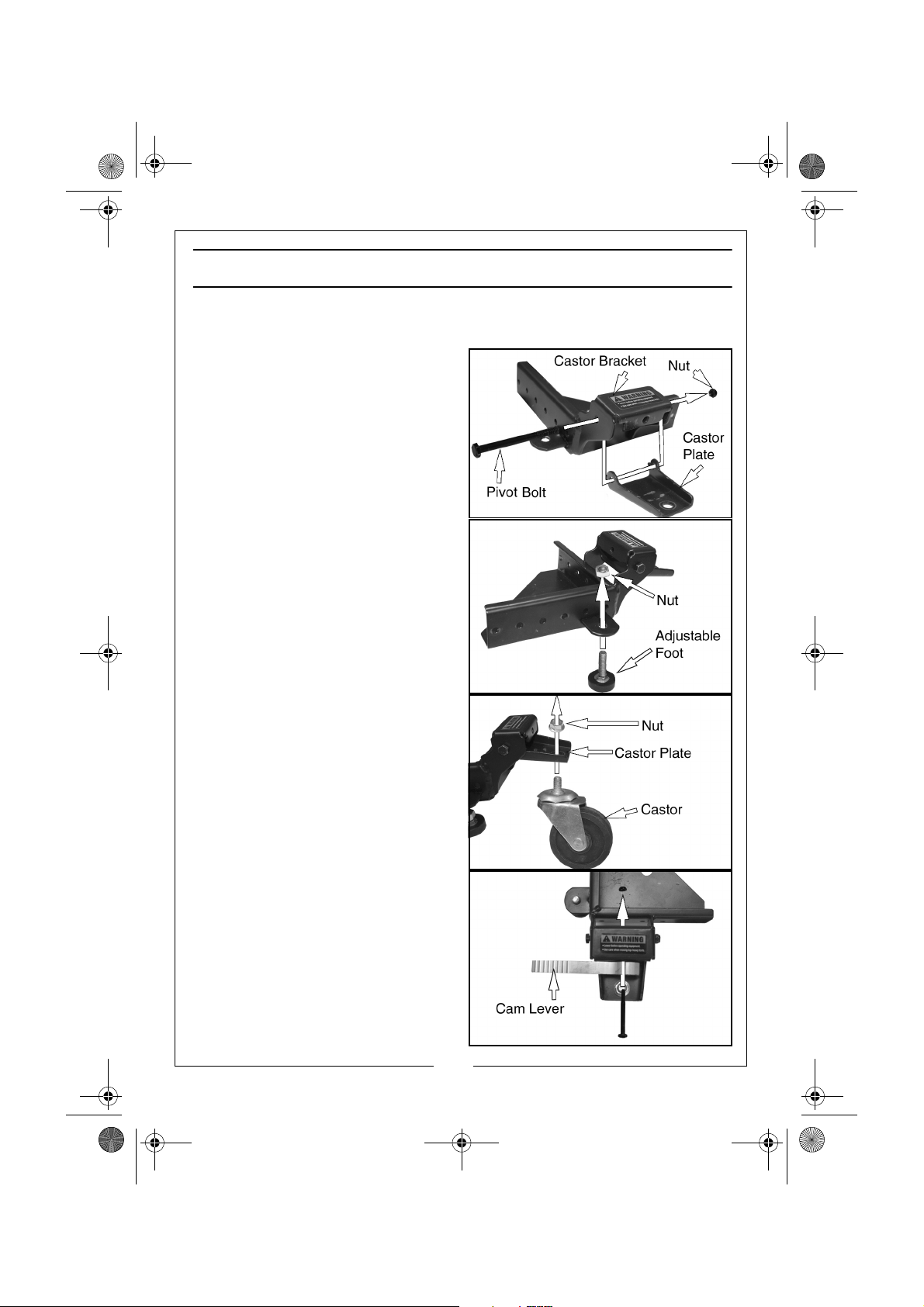
ASSEMBLE THE CASTOR BRACKETS
1. Attach castor plate to the castor
bracket using a pivot rod bolt and
self locking nut.
2. Screw the adjustable foot into the
threaded hole in the foot bracket.
3. Fit the large nut onto the top of
the adjustable foot.
4. Attach the castor to the castor
plate using a large flange nut.
5. Attach the cam lever to the
castor bracket using a 2½” cam
pivot bolt and self locking nut.
NOTE: Both cam levers should be
oriented towards the centre
of the base.
6. Follow steps 1-5 again for the
second castor bracket assembly.
4
Parts & Service: 020 8988 7400 / E-mail: [email protected] or [email protected]
Page 5
CUMB1 - Universal Mobile Base.fm Page 5 Thursday, June 20, 2013 10:35 AM
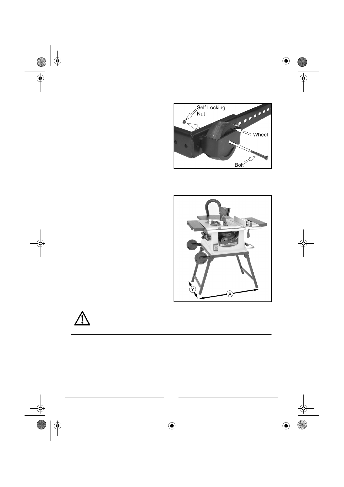
FITTING THE FIXED WHEELS
1. Position the wheel as shown.
2. Insert the 1¾” Wheel Axle Bolt
through hole in the outer edge of
the wheel housing, wheel, and
secure to corner using a self
locking nut.
NOTE: Use care not to overtighten
which would prevent the
wheel from turning.
MEASURE THE FOOTPRINT OF YOUR MACHINE
Take note of the outside
measurements of your machine and
add about 1" to the dimension. (1"
allows clearance for the fasteners).
Keep in mind the base is adjustable in
1" increments.
NOTE: A table saw is shown in this
example for illustration
purposes only.
CAUTION: WE RECOMMEND THAT YOU USE THIS MOBILE BASE WITH
MACHINES THAT HAVE A LOW CENTRE OF GRAVITY.
5
Parts & Service: 020 8988 7400 / E-mail: [email protected] or [email protected]
Page 6
CUMB1 - Universal Mobile Base.fm Page 6 Thursday, June 20, 2013 10:35 AM
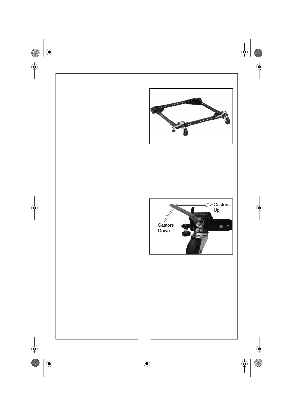
CONNECTING THE FOUR CORNERS TOGETHER
1. Select and arrange the corners
and side rails to assemble the
base the same size as your
machines footprint.
2. Bolt the side rails to the corners
and to each other using these
simple rules:
a. All connections require the use
of two ½” bolts and two small
flange nuts at each end of the
connections and if the rails join each other.
b. The side rails must be fitted into the corners as far as possible.
c. Keep your universal mobile base symmetrical.
NOTE: The nuts should be on the inside of the mobile base.
NOTE: Re-check dimensions, then tighten all bolts and nuts.
LOCKING AND UNLOCKING THE CASTOR WHEELS
1. Move the Cam Lever to the
‘castors up’ or ‘castors down’
position shown on the right.
2. When the castors are in the down
position the base will tilt slightly,
Make sure the any machine being
supported does not tip over,
especially if it is top heavy.
LEVELLING THE BASE
1. With the based raised (the castors locked in the down position), loosen the
locking nut on the adjustable feet.
2. Screw the foot in or out of the threaded hole as required, so that it makes
contact with the floor when not being supported by the castors.
• You will need to lower the base and check that the base is level
when it is not being supported by the castors.
3. Retighten the locking nut.
6
Parts & Service: 020 8988 7400 / E-mail: [email protected] or [email protected]
Page 7
CUMB1 - Universal Mobile Base.fm Page 7 Thursday, June 20, 2013 10:35 AM
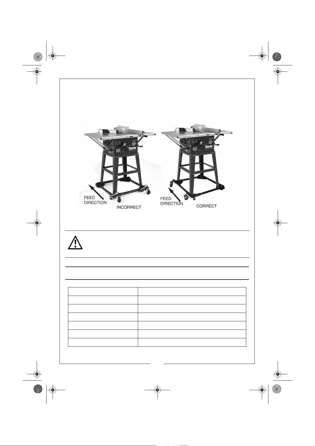
PLACING YOUR MACHINE ON THE BASE
1. With assistance, lift the machine to be mobilized onto the mobile base.
ORIENTATION
The feed direction must be at right angle to the orientation of the fixed wheels
to prevent the base from moving during machine operation.
GROUND CLEARANCE
This product should only be used on an even floor.
CAUTION: CHECK STABILITY IN BOTH THE UP AND DOWN POSITIONS
BEFORE USING. FAILURE TO FOLLOW SAFETY AND ASSEMBLY
INSTRUCTIONS MAY RESULT IN PERSONAL INJURY OR DAMAGE TO THE
PRODUCT.
SPECIFICATIONS
Model Number CUMB1
Part Number 7630211
Maximum Weight Loading 230 kg
Minimum Size 304 x 304 mm
Maximum Size (Square) 914 x 914 mm
Maximum Size (Rectangle) 508 x 1320 mm
Product Weight 7 kg
7
Parts & Service: 020 8988 7400 / E-mail: [email protected] or [email protected]
Page 8

CUMB1 - Universal Mobile Base.fm Page 8 Thursday, June 20, 2013 10:35 AM
 Loading...