

Page 1
WARNING: Read these instructions before using the press
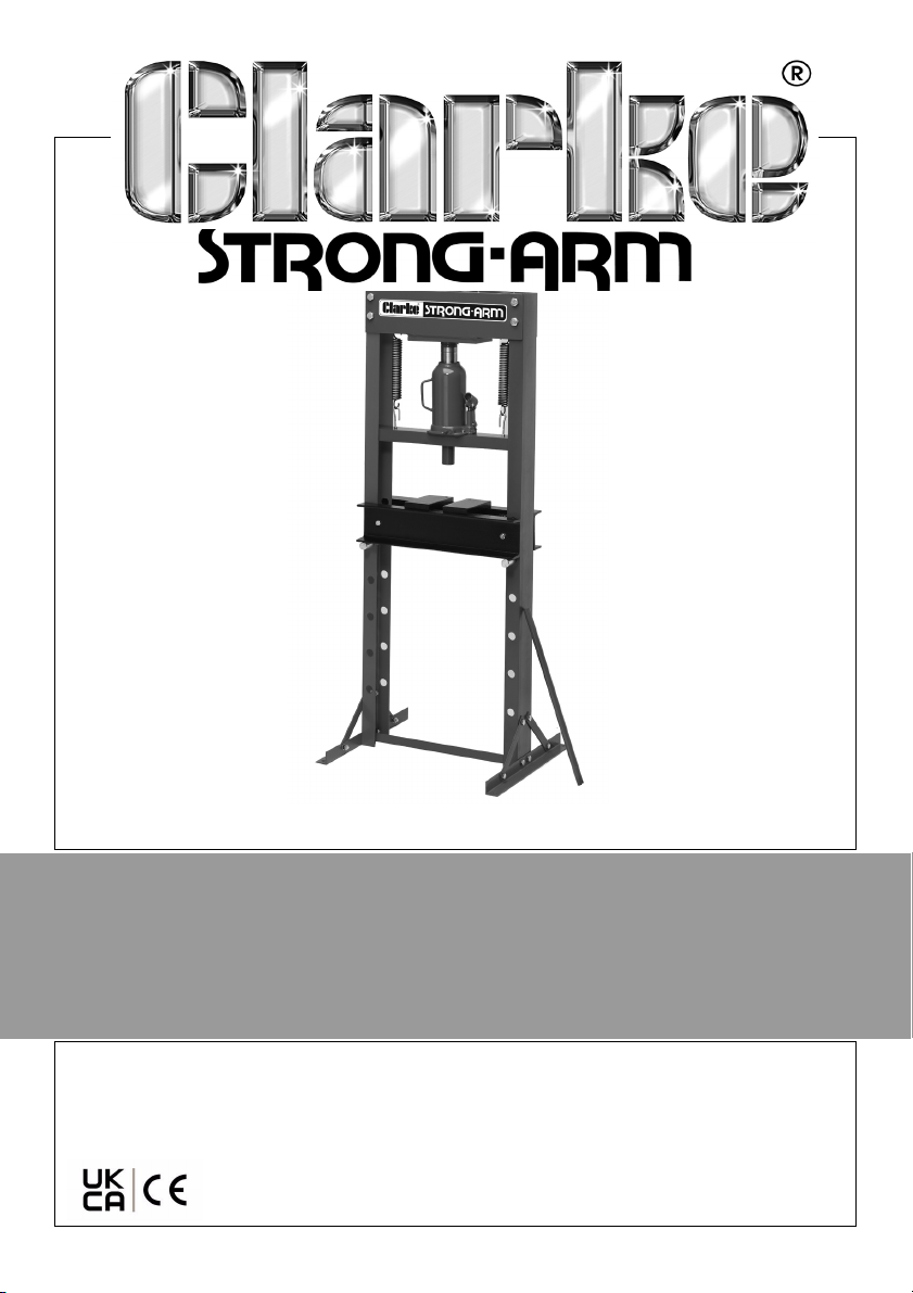
20 TONNE HYDRAULIC PRESS
MODEL NO: CSA20EP
PART NO: 7614052
OPERATION & MAINTENANCE
INSTRUCTIONS
ORIGINAL INSTRUCTIONS GC07/22
Page 2
INTRODUCTION
Thank you for purchasing this CLARKE 20 Tonne Hydraulic Press. Before
attempting to operate the press it is essential that you read this manual
thoroughly and carefully follow all instructions given. In doing so you will ensure
the safety of yourself and that of others around you, and you can also look
forward to the press giving you long and satisfactory service.
PRODUCT SPECIFICATIONS
Rated Load 20 Tonnes
Throat Width 670 mm
Throat Height (Ram to pressing plate) 937 mm
Platform at position 1
Platform at position 2
Platform at position 3
Platform at position 4
Ram Travel 150 mm
Ram travel per stroke 0.8mm
Number of strokes to full extension 188
Length of handle 500 mm
Oil Capacity/grade 0.51 L (HLP ISO32)
Dimensions (D x W x H) 540 x 640 x 1500 mm
Weight 85 kg
457 mm
577 mm
697 mm
817 mm
SAFETY SYMBOLS
Read instruction
manual before use
Wear Safety Shoes
The above safety symbols appear on the product.
2
Parts & Service: 020 8988 7400 / E-mail: [email protected] or [email protected]
Wear safety glasses
Page 3

SAFETY PRECAUTIONS
Due to the weight of the press, the help of an assistant will be beneficial during
assembly and installation.
ALWAYS operate the press with adequate light.
Before starting work, check for signs of cracked welds, loose or missing bolts, or
any other structural damage. Do not operate if any of these conditions exist.
Have repairs made only by authorised service centre.
NEVER tamper with any components. The safety valve is calibrated and
sealed at the factory; do not attempt to change the setting.
Use only the recommended hydraulic oil.
The components of this press are designed to withstand the rated capacity.
DO NOT substitute any other components or exceed the rated capacity of the
press.
Before applying pressure, ALWAYS ensure the workpiece is firmly secure and
stable.
ALWAYS clean up spills of hydraulic oil immediately as this can be dangerous in
a workshop environment.
DO NOT allow any person who is unfamiliar with hydraulic presses to use the
press unless they are under direct supervision.
DO NOT stand directly in front of the press when it is in use.
ALWAYS apply the load under the centre of the ram. Offset loads can
damage the ram and may cause the work piece to be ejected.
ALWAYS ensure the work piece is properly supported by the press bed.
When using accessories such as pressing plates, be certain they are centered
below the ram and are in full contact with the bed.
Parts being pressed may shatter or be ejected from the press. In the case of
varied applications, it is your responsibility to always use adequate guards,
and wear eye protection and protective clothing when using this press.
Keep hands and fingers away from parts that may pinch or shift.
NEVER use extension tubes to increase the length of the pump handle.
Excessive effort can cause damage and/or accidents.
Failure to heed these warnings may result in damage to the equipment, or
serious personal injury.
3
Parts & Service: 020 8988 7400 / E-mail: [email protected] or [email protected]
Page 4
UNPACKING
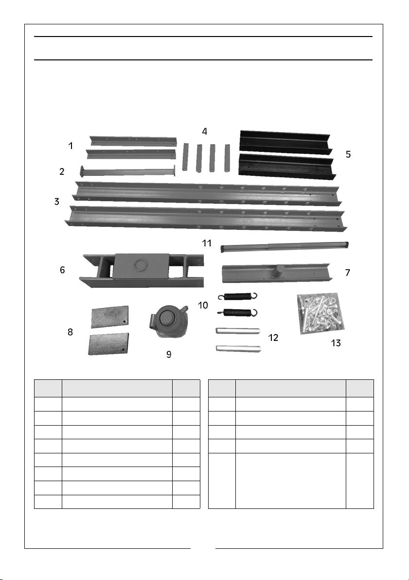
Ensure the press components suffered no damage during transit and that all
components are present. Should any loss or damage become apparent,
please contact your CLARKE dealer immediately.
ID DESCRIPTION QTY ID DESCRIPTION QTY
1 Foot 2 9 Bottle Jack 1
2 Bottom Cross Member 1 10 Spring 2
3 Side Support 2 11 Bottle Jack Handle 1
4 Foot Brace 4 12 Bed Supporting Pins 2
5 Pressing Bed 2 13 Fixings pack, containing
6 Cross Beam 1
7 Middle Bolster 1
8 Pressing Plate 2
4
Parts & Service: 020 8988 7400 / E-mail: [email protected] or [email protected]
bolts, nuts, washers and
attachment hooks
itemised on page 13.
Page 5
ASSEMBLY
The press must be firmly secured to a solid level floor such as concrete, using
expansion bolts (not supplied). Holes are provided in the foot sections for this
purpose. Do not locate your press where it will be open to the elements, as
harsh weather conditions will damage the hydraulic parts.
Due to the weight of the components, we recommend that the press is
assembled by two people.
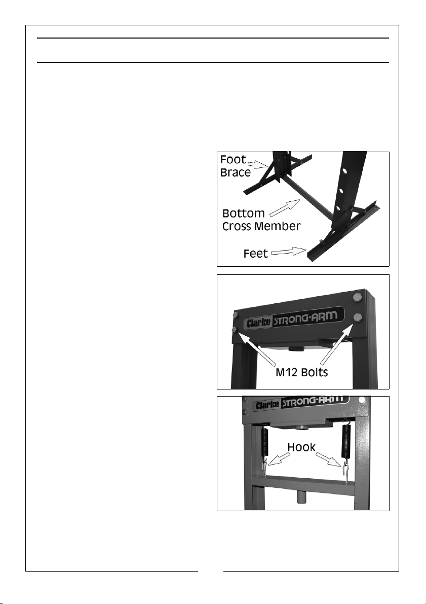
1. Attach the feet and the bottom
cross member to the side
supports, using the M12 nuts, bolts
and washers.
2. Add the foot braces to each side
using the remaining M10 nuts,
bolts and washers.
3. Bolt the cross beam to the side
supports, securing it with the M16
bolts, nuts and washers.
• Assemble loosely before
tightening all fastenings.
4. With the help of an assistant,
manoeuvre the frame to its
intended location in the
workshop.
5. Fix the 2x hooks to the moving
cross beam using the nuts
supplied. Take the two springs and
hook them to their positions on the
moving beam. Support the
moving beam and attach the
other end of the springs to the
cross beam.
5
Parts & Service: 020 8988 7400 / E-mail: [email protected] or [email protected]
Page 6
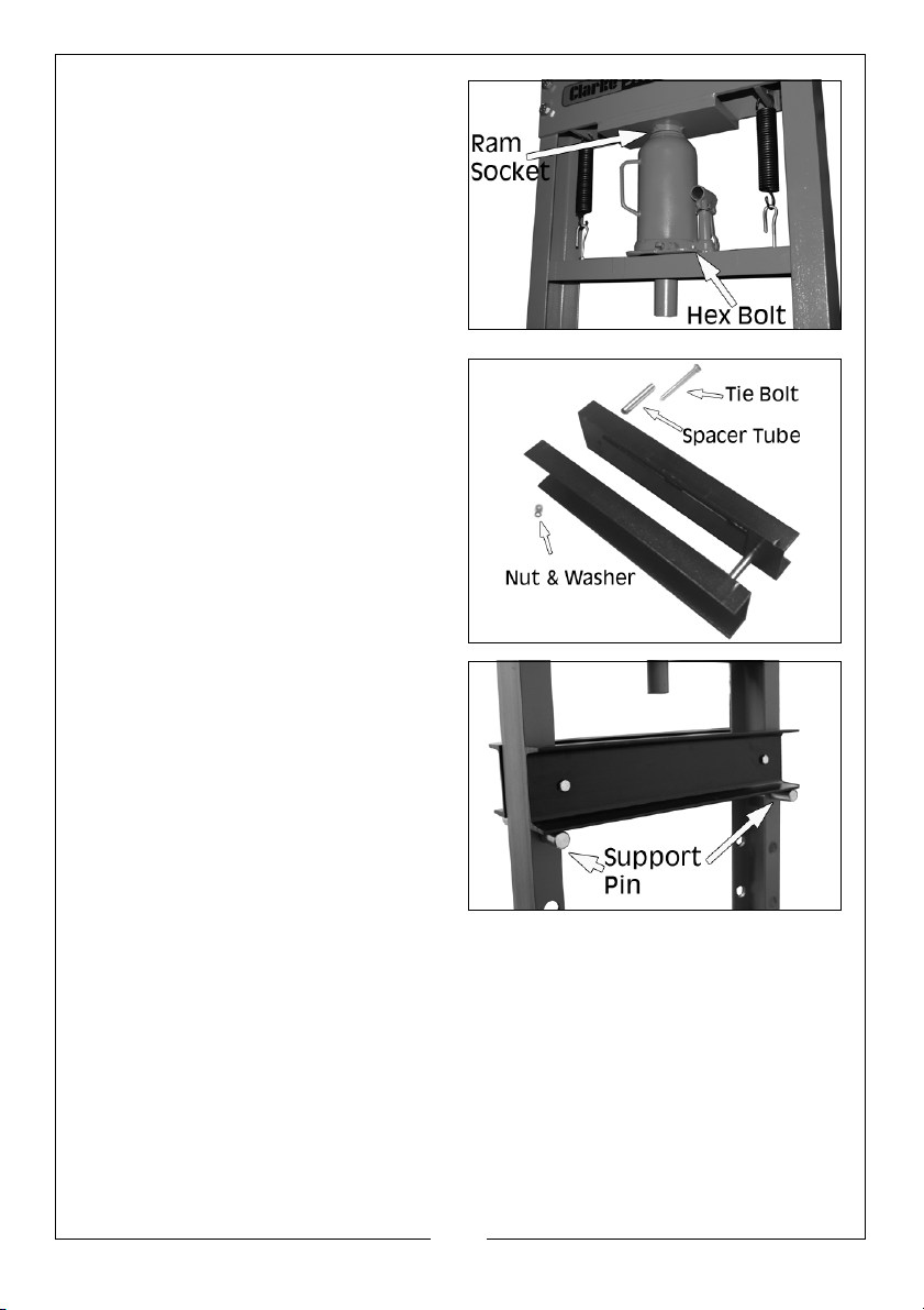
6. Take the bottle jack unit, and by
pressing down on the moving
cross beam against the resistance
of the springs, manoeuvre the
jack so that the jack ram sits in the
socket below the cross beam.
7. Using the small hex bolt and nut,
secure the jack to the beam.
• The jack will remain self-centred
during use.
Bolt the two halves of the pressing
bed together using the long bolts
with nuts and spacer tubes supplied.
8. Insert the bed support pins into
the holes in the side support at a
height of your choosing. Then
lower the pressing bed onto the
pins.
6
Parts & Service: 020 8988 7400 / E-mail: [email protected] or [email protected]
Page 7
PREPARATION
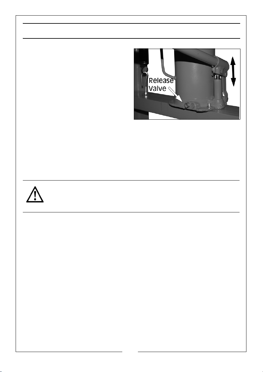
1. Before using the press, purge any
air from the jack by using the
crimped end of the handle to
open the release valve (turning it
anti-clockwise) and pumping the
jack several full strokes to
eliminate any air bubbles.
2. Check all parts are secure and
correctly aligned before using the
press.
POSITIONING THE BED
Due to the weight of the bed, we recommend that you get assistance from
another person when changing the bed height.
1. Raise one side of the bed and insert a supporting pin into the next locating
hole.
2. Repeat at the other end to level the bed..
CAUTION: IT IS SAFER AND EASIER IF THE BED HEIGHT IS ONLY RAISED OR
LOWERED ONE HOLE AT A TIME, WORKING ALTERNATELY FROM ONE
SIDE AND THEN THE OTHER UNLESS AN ASSISTANT IS AVAILABLE TO
SUPPORT THE WEIGHT OF THE BED WHILE THE PINS ARE INSERTED.
3. Position the bed at the desired height, so that it will be as close as possible
to the ram when the workpiece is mounted on it.
7
Parts & Service: 020 8988 7400 / E-mail: [email protected] or [email protected]
Page 8
OPERATION
WARNING: FAILURE TO HEED THE WARNINGS ON PAGE 3 MAY RESULT IN
DAMAGE TO THE EQUIPMENT OR COMPONENT FAILURE RESULTING IN
PROPERTY DAMAGE, PERSONAL, OR EVEN INJURY.
NEVER USE EXTENSIONS TO THE RAM PUMPING HANDLE
1. The press is now ready for use. Place the workpiece on the bed. It must be
completely stable and supported by packing or shims where required. A
pair of pressing plates are supplied, which lay flat on the bed. Place the
workpiece on these to give it stability.
CAUTION: DO NOT POINT LOAD THESE ACCESSORIES AS THEY ARE NOT
DESIGNED TO TAKE THE FULL FORCE OF THE RAM IN ONE SPOT. ENSURE
THEY ARE ADEQUATELY SUPPORTED.
NOTE: Any packing pieces or shims used MUST be capable of
withstanding the pressure that will be brought to bear, and MUST
be of sufficient size with sufficient surface area, so as to avoid the
possibility of slipping or springing out. Mating surfaces MUST be
horizontal so that the force being exerted will NOT be at an angle.
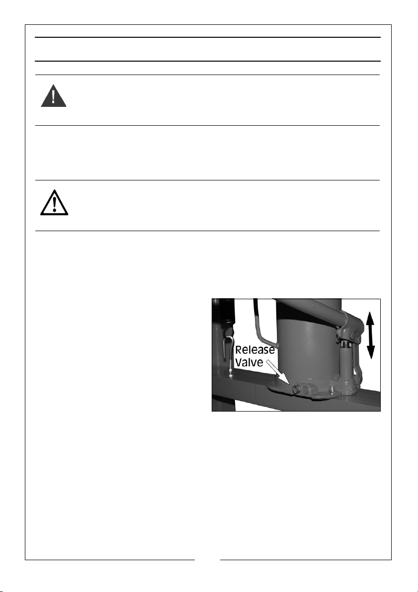
2. Using the crimped end of the
handle, close the release valve by
turning it clockwise until tightly
closed.
3. Pump the handle to bring the ram
very lightly into contact with the
workpiece.
4. Position the workpiece so that the
desired point of contact is directly
beneath the centre of the ram.
5. When satisfied that the workpiece is correctly aligned and is completely
stable in that position, slowly pump the handle so that the ram begins to
exert pressure on the workpiece.
6. Continue to pump the handle and constantly monitor the process,
ensuring the ram and work remain completely in line and there is no risk of
slipping.
7. When the task is complete, turn the release valve anticlockwise in small
increments to release ram pressure and allow removal of the workpiece.
8
Parts & Service: 020 8988 7400 / E-mail: [email protected] or [email protected]
Page 9

MAINTENANCE
ROUTINELY
A visual inspection must be made before use of the press, checking for leaking
hydraulic fluid and damaged, loose, or missing parts.
Owners and/or users should be aware that repair of this equipment requires
specialised knowledge and facilities. It is recommended that a routine
inspection of the press be made and any defective parts be replaced with
genuine CLARKE parts.
If thepress appears to be damaged in any way, is found to be badly worn or
operates abnormally SHOULD BE REMOVED FROM SERVICE until the necessary
repairs are made.
If the press is not to be used for any length of time, store it with the ram piston
withdrawn to protect the moving parts.
PERIODICALLY
Periodically check the press frame to make sure all bolts are tight and inspect
for cracked welds, bent, loose or missing parts. If corrosion is found it should be
removed completely and the paint restored.
Check the hydraulic jack for leaks. Replace or properly repair any damaged
or leaking hydraulic components before using. In the event of leaking seals, oil
can be topped up via the plug on the jack. Oil should be level with the
bottom of the hole. If necessary top up with CLARKE hydraulic oil, Part No.
3050830. This task is carried out with the ram fully retracted.
In the event of leakage, oil can be topped up by removing the filler plug on
the reservoir and topping up level with the plug.
DISPOSAL OF UNWANTED MATERIALS
One of the most damaging sources of environmental pollution is oil products.
Never throw away used oil with domestic refuse or flush it down a sink or drain.
Collect any oil in a leak proof container and take it to your local waste
disposal site.
Should hydraulic components become completely unserviceable and require
disposal, draw off the oil into an approved container and dispose of the
product and the oil according to local regulations.
9
Parts & Service: 020 8988 7400 / E-mail: [email protected] or [email protected]
Page 10
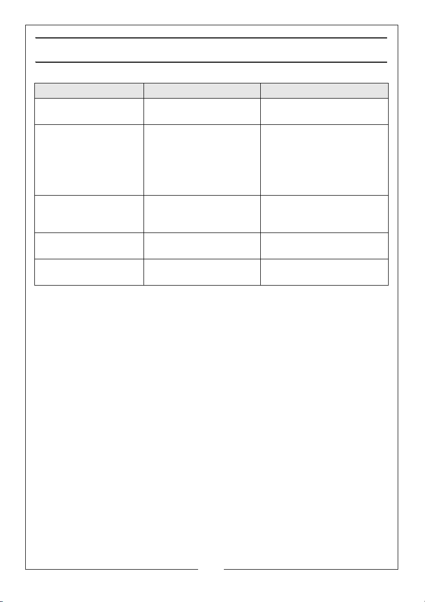
TROUBLESHOOTING
Problem Probable Cause Remedy
Pump unit will not work Dirt on valve seat/worn
seals
Pump will not produce
pressure
Pump feels hesitant
under load
Pump will not deliver
pressure
Pump feels hesitant
under load
Pump will not lower
completely
Air-lock Open the release valve
Reservoir could be overfilled or have low oil level.
Pump cup seal could be
worn out.
Air-lock Release air by removing
Bleed pump or have unit
overhauled with new seals
and remove the oil filler
plug. Pump the handle a
couple of full strokes and
close the release valve.
Replace the filler plug.
Check oil level by removing
the filler plug & topping up
if required.
Have the cup seal
replaced.
the filler plug.
10
Parts & Service: 020 8988 7400 / E-mail: [email protected] or [email protected]
Page 11
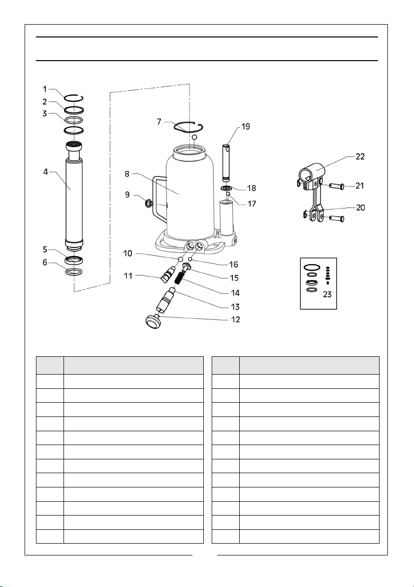
COMPONENT PARTS - BOTTLE JACK
ID DESCRIPTION ID DESCRIPTION
1 Circlip 13 Adjusting Screw Assembly
2 Rectangular Ring 14 Spring
3 O-Ring 15 Spring Holder
4 Piston Rod Assembly 16 Steel Ball Bearing, 3mm
5 Bowl Washer 17 Steel Ball Bearing, 5mm
6 O-Ring 18 Bowl Washer
7 Circlip 19 Pump Plunger Assembly
8 Main Base Unit 20 Cotter Pin
9 Oil Plug 21 Pin
10 Steel Ball Bearing, 6mm 22 Handle Socket Assembly
11 Release Value Assembly 23 Seal Kit
12 Plastic Plug
11
Parts & Service: 020 8988 7400 / E-mail: [email protected] or [email protected]
Page 12
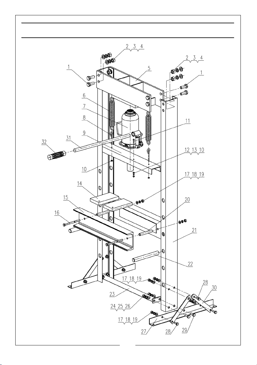
COMPONENT PARTS - FRAME
12
Parts & Service: 020 8988 7400 / E-mail: [email protected] or [email protected]
Page 13
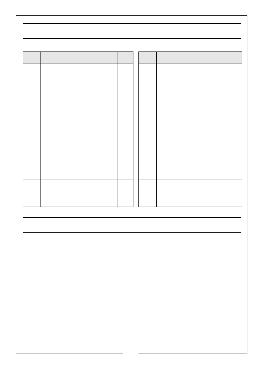
COMPONENT PARTS - FRAME
ID DESCRIPTION QTY ID DESCRIPTION QTY
1 Bolt, M16 x 40 8 17 Washer, 10 2
2 Washer, 16 8 18 Spring Washer, 10 2
3 Nut, M16 8 19 Nut, M10 2
4 Spring Washer, 16 8 20 Spacer Tube 2
5 Top Cross Beam 1 21 Side Column 2
6 Spring 2 22 Bed Support Pins 2
7 Bottle Jack 1 23 Bottom Cross Member 1
8 Hook 2 24 Nut, M12 4
9 Moving Cross Beam 1 25 Spring Washer, 12 4
10 Nut, M6 1 26 Washer, 12 4
11 Socket Screw, M6 x 20 1 27 Foot Rail 2
12 Washer, 6 1 28 Bolt, M10 x 25 8
13 Spring Washer, 6 1 29 Bolt, M12 x 30 4
14 Pressing Plates 2 30 Foot Brace 4
15 Pressing Bed 2 31 Handle 1
16 Bolt, M10 x 130 2 32 Handle Sleeve 1
GUARANTEE
This CLARKE product is guaranteed against faulty manufacture for a period of
12 months from the date of purchase. Please keep your receipt as proof of
purchase.
This guarantee is invalid if the product is found to have been abused or
tampered with in any way, or not used for the purpose for which it was
intended.
Faulty goods should be returned to their place of purchase, no product can
be returned to us without prior permission.
This guarantee does not effect your statutory rights.
13
Parts & Service: 020 8988 7400 / E-mail: [email protected] or [email protected]
Page 14
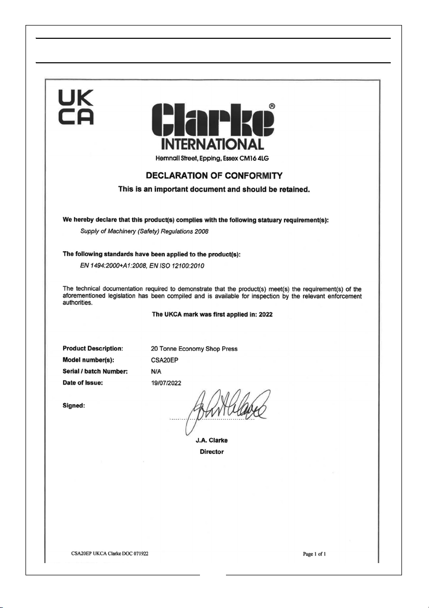
DECLARATION OF CONFORMITY-UK
14
Parts & Service: 020 8988 7400 / E-mail: [email protected] or [email protected]
Page 15
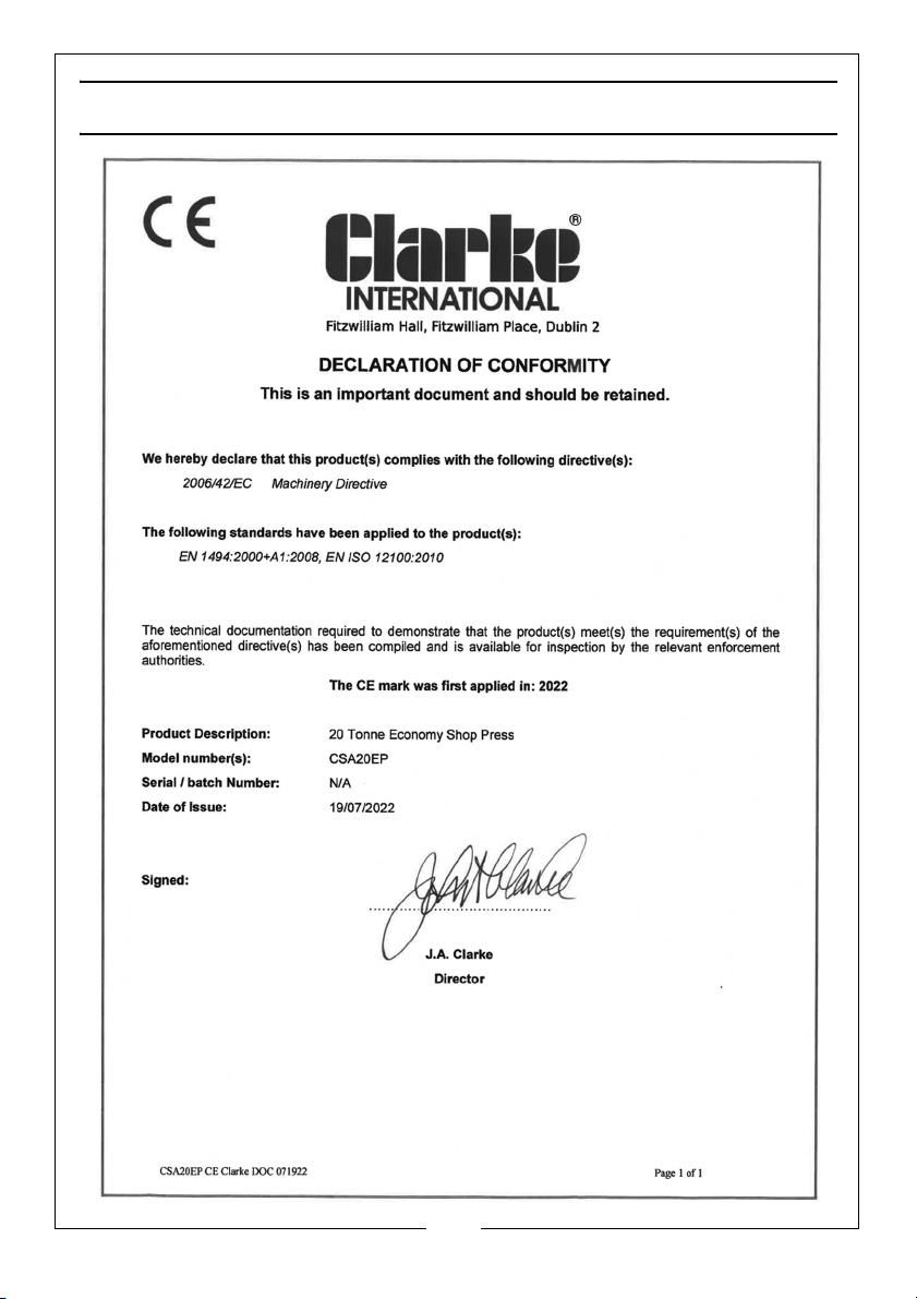
DECLARATION OF CONFORMITY-EU
15
Parts & Service: 020 8988 7400 / E-mail: [email protected] or [email protected]
Page 16
 Loading...