

Page 1

GANTRY CRANE
MODEL NO: CWGC1000
PART NO: 7612570
ASSEMBLY & USER INSTRUCTIONS
ORIGINAL INSTRUCTIONS GC0320 - ISS 1
Page 2
INTRODUCTION
Thank you for purchasing this CLARKE Gantry Crane.
Before attempting to operate the product, it is essential that you read this
manual thoroughly and carefully follow all instructions given. In doing so you
will ensure the safety of yourself and that of others around you, and you can
also look forward to the product giving you long and satisfactory service.
Please keep these instructions in a safe place for future reference.
SPECIFICATIONS
Model CWGC1000
Max Capacity (SWL) 1000 kg (1 Tonne)
Net Weight 128 kg
Dimensions (L x W x H) 2600 x 1200 x 3720/2520 (max/min. height)
Maximum lift height 3600 mm
Minimum lift height 2395 mm
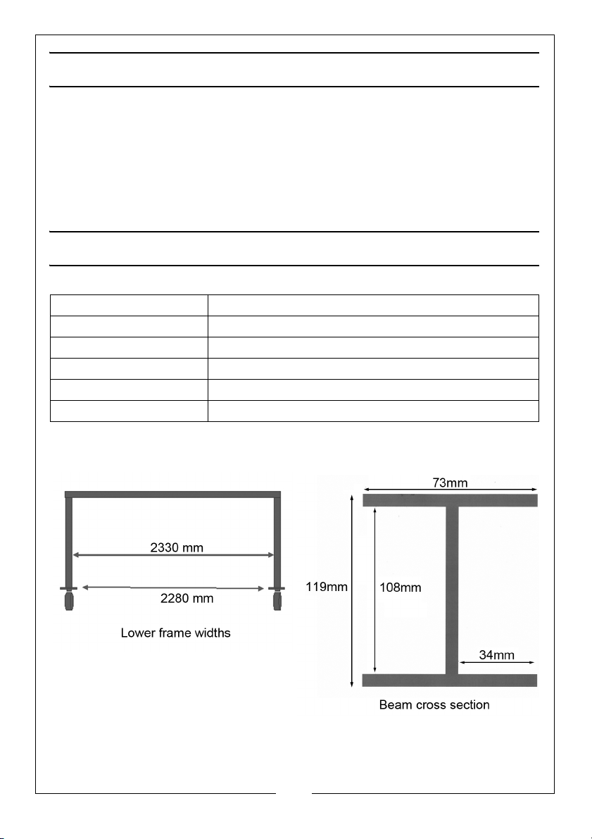
Widths are shown between the narrowest points (castor plates), and between
the uprights.
2
Parts & Service: 020 8988 7400 / E-mail: [email protected] or [email protected]
Page 3

SAFETY PRECAUTIONS
Always read instructions before setting up the equipment and before use.
Failure to heed these warnings may result in damage to equipment or serious
personal injury.
WORKPLACE SAFETY
1. ALWAYS inspect the gantry before use to ensure it is correctly assembled
and in good condition and replace any damaged or worn parts.
2. Only use the gantry on a flat, solid, level surface preferably concrete which
is capable of bearing the weight when loaded. Never work on soft/
unmade ground as the castors may sink in causing the gantry to topple.
3. Ensure the gantry operator is trained in both operation and safety aspects.
4. DO NOT allow personnel to use the gantry unless they have read these
safety precautions.
5. Use the gantry in a suitable, well lit work area. which is tidy and free from
unrelated items.
6. DO NOT use the gantry when you are tired or under the influence of
alcohol, drugs or intoxicating medication.
7. Keep all bystanders at a safe distance whilst the gantry is in use.
8. DO NOT over-reach. Keep your proper footing and balance at all times.
9. Safety equipment such as gloves and non-skid safety shoes will reduce the
possibility of personal injuries.
INSPECTION BEFORE USE
1. ALWAYS visually inspect the gantry before use, to ensure that all parts are
correctly located and secure. Check for cracks, deformation or other signs
of damage or worn parts and check the castors for damage. Do not use
the gantry unless it is totally sound.
2. Check castors to ensure they move freely without undue wear to their
pivots and that the wheels are not cracked or damaged.
SAFE OPERATING PRACTICE
1. Only use chains, slings, hooks etc. with a rated capacity equal to, or
greater than that of the load and the gantry. Check that they are secure
and will not slip under load.
2. NEVER exceed the safe working load capacities specified.
3
Parts & Service: 020 8988 7400 / E-mail: [email protected] or [email protected]
Page 4

3. Lower the load as much as possible before moving the gantry. Do not use
the gantry to transport loads over long distances.
4. DO NOT allow the load to swing or drop suddenly whilst moving or
lowering.
5. DO NOT use this gantry to lift people or animals.
6. DO NOT work under any raised load.
7. NEVER climb on, or attempt to ride on the gantry.
8. Take care not to trap your fingers in the adjustable parts of the gantry.
9. Due to the weight of the loaded gantry, the help of an assistant will be
beneficial when moving the gantry around.
10. This is a heavy item (128kg). Take care when positioning or adjusting.
11. NEVER attempt to move a loaded gantry across a floor having cracks,
pebbles, or other obstacles which might impede its movement.
12. DO NOT move the gantry while heavily loaded in case it becomes
unstable. Do not use the loaded gantry on sloping ground.
13. ALWAYS ensure the crossbeam is level at all times.
14. DO NOT leave the load suspended when the gantry is unattended.
15. ALWAYS ensure the load is centred beneath the beam before lifting.
16. ALWAYS apply the brakes on each of the castors when the gantry is not
being moved around.
17. DO NOT push or pull the gantry crane with a fork truck or any other vehicle.
CARE OF THE GANTRY
1. Ensure that the gantry is properly maintained at all times and that no
corrosion is allowed to weaken any components.
2. If replacing parts only use those supplied by CLARKE International.
3. If the gantry has been subjected to an abnormal load or shock it should be
removed from service immediately and inspected by a qualified person.
4. NEVER tamper with the gantry or modify it in any way as this could prove to
be dangerous and will invalidate the guarantee. Only use the gantry for
the purpose for which it is intended.
5. The components of this gantry are designed to withstand the rated
capacity. Do not substitute any other components or exceed the rated
capacity of the gantry.
6. If the load capacity decal becomes worn or illegible contact CLARKE Parts
and service department on 0208 988 7400 for a replacement.
4
Parts & Service: 020 8988 7400 / E-mail: [email protected] or [email protected]
Page 5

UNPACKING AND PREPARATION
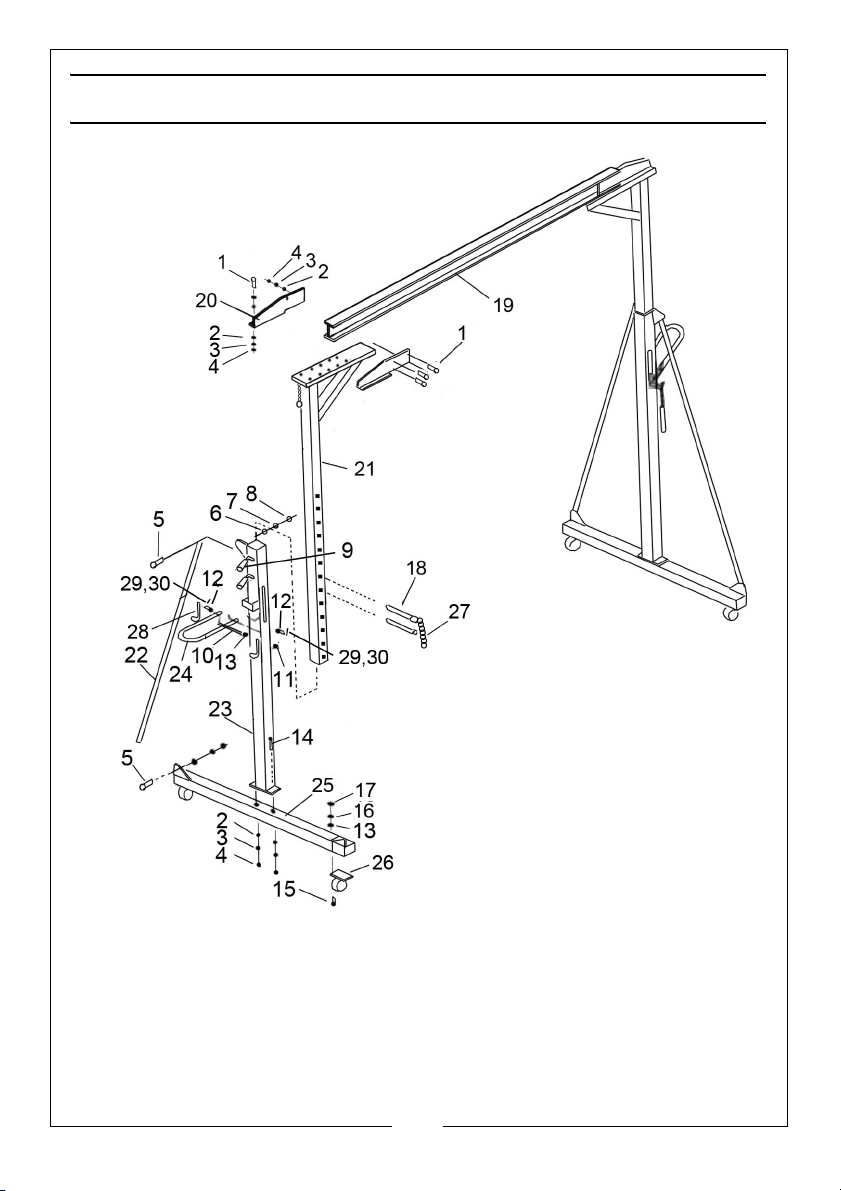
Using a clean level area, unpack and check/identity of all components
including nuts, bolts and washers. Lay out and identify the components as
shown in parts diagram on page 6.
During assembly, nuts and bolts should only be finger tightened. Final
tightening can be carried out when assembly is completed.
Where bolts are mentioned, it Is assumed that the appropriate washers, lock
washers and nuts are also fitted.
COMPONENT PARTS
ITEM DESCRIPTION QTY ITEM DESCRIPTION QTY
1 Bolt M12 x 35 24 16 10 dia spring washer 16
2 12 dia washer 28 17 M10 nut 16
3 12 dia spring washer 28 18 Pin 4
4 M12 nut 28 19 Crossbeam 1
5 Bolt M14 x 40 8 20 Connecting plate 4
6 14 dia washer 8 21 Inner vertical post 2
7 14 dia spring washer 8 22 Support tube 4
8 M14 nut 8 23 Outer vertical post 2
9 Locking Handle 4 24 Lifting Lever/Handle 2
10 Pivot Shaft 2 25 Base frame 2
11 M10 nut 4 26 Castor wheel 4
12 Hinge Pin 4 27 Chain 2
13 10 dia flat washer 20 28 Lifting hook 4
14 Bolt M12 x 100 4 29 Washer 4
15 Bolt M10 x 30 16 30 Split pin 4
5
Parts & Service: 020 8988 7400 / E-mail: [email protected] or [email protected]
Page 6
Page 7

ASSEMBLY
REFER TO THE PARTS DIAGRAM ON PAGE 6
1. Take the outer vertical posts (23) and bolt them to the base frames (25)
using the M12 x 100 bolts, nuts and washers shown (14, 2, 3, 4).
2. Take the four support tubes (22) and bolt them to the base frames (25) and
outer vertical posts using M14 bolts (5), nuts and washers (6,7 & 8) at each
end.
3. Screw the locking handles (9) to the outer posts (23).
4. Bolt the connecting plates (20) to the cross beam (19) before bolting the
connecting plates to the inner vertical posts (21).
5. With the help of an assistant, insert the inner vertical posts (21) into the
outer posts (23).
• This may be best done with the assembly laying down.
6. Bolt the four castors (26) to the corners of the base frame assembly using
M10 bolt, nuts and washers (15,16 &17).
7. Ensure that the inner uprights have slid into the outer uprights as far as they
will go before standing the completed assembly upright.
8. Attach the lifting hooks (28) to the lifting handles (24) using the pivot pins,
washers and split pins (29/30/31).
9. Connect the lifting handles to the frame using long cross bolts (10) and (12)
with the M8 nuts (13).
10. Finally check to ensure that all nuts are fully tightened and the castors
operate freely.
NOTE: DO NOT OVERTIGHTEN ANY PART WHICH MAY CAUSE DISTORTION
11. With the help of an assistant, raise the upper assembly to the height
required and insert the locking pins (18) into the holes in each upright.
12. EXERCISE GREAT CARE WHEN LIFTING/LOWERING HEAVY LOADS. Make sure
that any hoist, sling or hook is directly above the centre of gravity of the
load.
7
Parts & Service: 020 8988 7400 / E-mail: [email protected] or [email protected]
Page 8
USING THE GANTRY
INSTALLING A HOIST
1. Install a suitable chain block or
hoist (not supplied) to the
crossbeam following the
instructions supplied with the hoist.
Note the dimensions of the
crossbeam shown on page 2.
NOTE: When raising and lowering
the crossbeam, always use
two people and synchronise
the raising/lowering
operation.
LIFTING THE CROSSBEAM
WARNING: NOT NOT ATTEMPT TO ALTER THE CROSSBEAM HEIGHT WHILE
UNDER LOAD.
1. Ensure the pin is in the lower
location on each side as shown in
Fig 3.
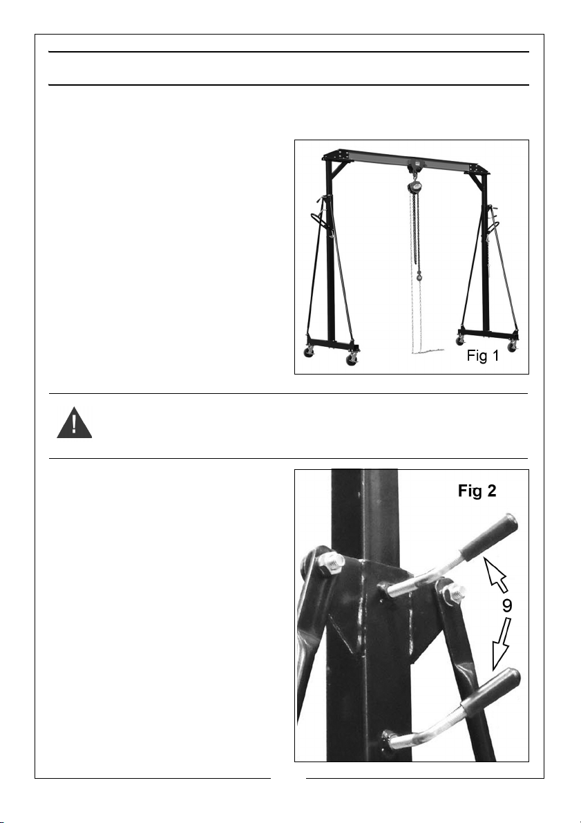
2. Loosen the two clamping handles
on each side shown in Fig 2.
8
Parts & Service: 020 8988 7400 / E-mail: [email protected] or [email protected]
Page 9
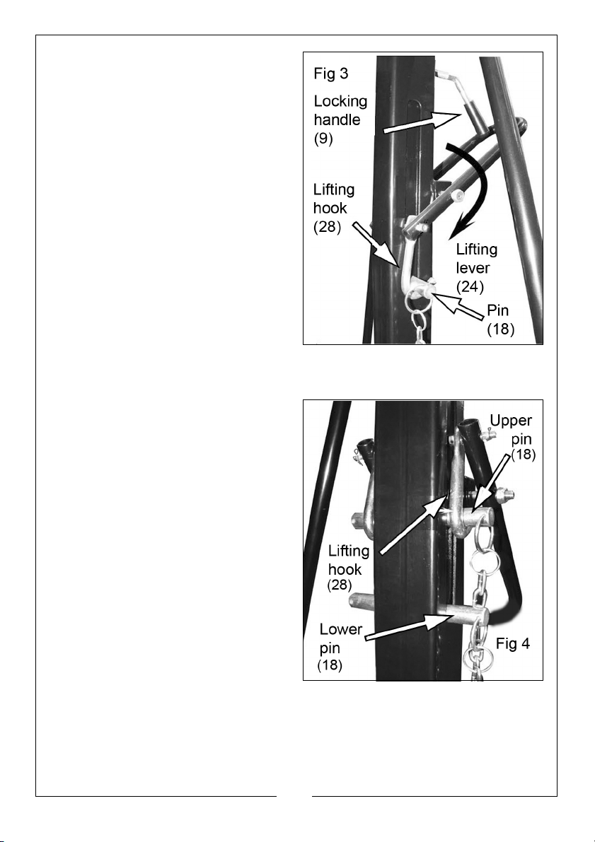
3. Engage the lifting hook with the
pin in the lower location on each
side.
4. Lift the lower pin by pressing down
on the outer ends of the lifting
levers.
5. When the next locating hole
appears in the slot, insert the other
pin into it (thus becoming the
lower pin) and lower gently until it
is bearing the weight of the parts
above. Repeat until the required
height is reached. (13 holes are
provided).
6. Clamp the uprights by tightening
the locking handles on each side.
LOWERING THE CROSSBEAM
This should be performed in unison with both uprights, ensuring that the crossbeam stays level.
1. Loosen the locking handles.
2. Place the pin in the upper hole
location.
3. Engage the lifting hook with the
upper pin.
4. Using the lifting handles, lift the pin
to release the weight on the lower
pin.
5. Remove the lower pin and lower
the upper pin gently to the lower
location.
6. Repeat until the required height is
reached.
7. Clamp the upright securely by
tightening the clamping handles.
9
Parts & Service: 020 8988 7400 / E-mail: [email protected] or [email protected]
Page 10
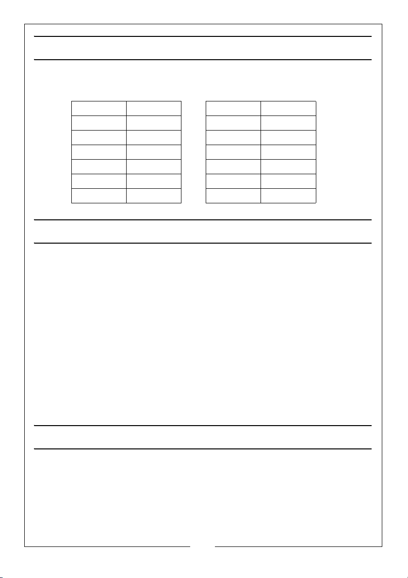
BEAM HEIGHT SETTINGS
The underside of the crossbeam can be set at the following heights above
ground level.
1 2395 mm 8 3100 mm
2 2500 mm 9 3200 mm
3 2600 mm 10 3300 mm
4 2700 mm 11 3400 mm
5 2800 mm 12 3500 mm
6 2900 mm 13 3600 mm
7 3000 mm
CARE AND MAINTENANCE
1. Do not leave the gantry in the open or exposed to the elements. Keep it
dry and clean under cover.
2. Always visually inspect the gantry before use, to ensure that all parts are
correctly located and secure. Check for signs of damage or worn parts
and check the wheels and castors for serviceability.
3. The gantry should be fully inspected annually by a competent person.
4. Each load-bearing bolt should be inspected for wear, deformation or
cracks. If any are apparent, the bolt should be renewed, like for like.
5. Check the castors to ensure they move freely without undue wear to their
spindles and that the wheels are not cracked or damaged.
6. Remove any rust and repaint to prevent further corrosion.
7. Ensure that warning labels are in place and clearly legible.
GUARANTEE
This CLARKE product is guaranteed against faulty manufacture for a period of
12 months from the date of purchase. Please keep your receipt as proof of
purchase.This guarantee is invalid if the product is found to have been abused
or tampered with in any way, or not used for the purpose for which it was
intended. Faulty goods should be returned to their place of purchase, no
product can be returned to us without prior permission. This guarantee does
not effect your statutory rights.
10
Parts & Service: 020 8988 7400 / E-mail: [email protected] or [email protected]
Page 11

DECLARATION OF CONFORMITY
11
Parts & Service: 020 8988 7400 / E-mail: [email protected] or [email protected]
Page 12

 Loading...