

Page 1
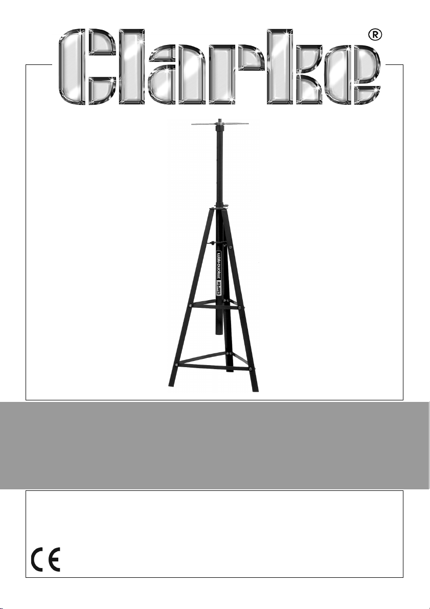
AUTOMOTIVE SUPPORT STAND
MODEL NO: CTS4000B
PART NO: 7600200
INSTRUCTIONS
GC0220 - ISS 4
Page 2
SAFETY WARNINGS - ALWAYS READ BEFORE USE
1. Read these instructions carefully before use.
2. ALWAYS inspect before each use, to ensure the frame is not bent or twisted
and that there are no cracked welds etc. Should any damage be
apparent, or if the stand has been subjected to an abnormal shock, it
should be removed from service and repaired by a qualified technician.
3. DO NOT use this tool as a jack.
4. DO NOT use this stand to support a vehicle transmission.
5. Do not exceed the stand’s maximum load (750kg).
6. Use only as specified in this manual.
7. NEVER let children play around the stand.
8. Replace the safety warning label if it becomes unreadable.
9. For your safety, do not modify this stand in any way.
USING THE SUPPORT STAND
WARNING: BEFORE USE, MAKE SURE THAT THERE IS NO DAMAGE TO ANY
PART OF THE STAND. IF THERE IS, DO NOT USE.
WARNING: IT MUST BE ENSURED THAT THE LOAD IS CAREFULLY LOCATED
ONTO THE CENTRE OF THE STAND SADDLE. FAILURE TO DO THIS CAN
RESULT IN DAMAGE TO THE STAND, LOSS OF SUPPORT TO THE LOAD,
SERIOUS PERSONAL INJURY OR LOSS OF LIFE.
WARNING: DO NOT EXCEED THE RATED LOAD.
WARNING: USE ONLY ON A HARD, FLAT SURFACE, E.G. CONCRETE.
This Support Stand is designed for many support uses e.g. exhausts, and
requires assembling according to the drawing opposite.
1. Rotate the Screw Nut (3), anticlockwise, using the handles (10), to lower the
Saddle (1), as far as possible.
2. Grasp one of the handles (10), and taking the weight of the complete
Upper Assembly Saddle, Screw Rod (2), Screw Nut, Handles and Tube Insert
(5), remove the Locking Pin (11), which secures the Upper Assembly to the
Support Post (7).
3. Raise the Upper Assembly as high as necessary so that the Saddle is as near
as possible to the load.
2
Parts & Service: 020 8988 7400 / E-mail: [email protected] or [email protected]
Page 3
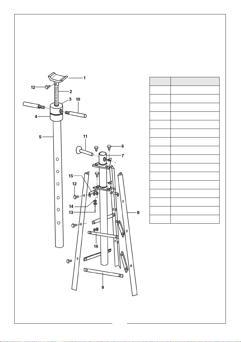
4. Line up one of the holes in the Tube Insert (5) with the hole in the top of the
Support Post and locate using the Locking Pin.
5. Finally, screw the Screw Nut clockwise so that the Saddle contacts the load
at a suitable support point...careless positioning could result in damage to
the load. Continue to raise the saddle, but only enough to take the weight
of the load.
Ref No Description
1Saddle
2Screw Rod
3 Screw Nut
4 Bearing
5 Tube Insert
6 Bolt M10 x 25
7 Support Post
8Leg
9Lower Strut
10 Handle
11 Locking Pin
12 Bolt M10 x 20
13 Nut M10
14 Flat Washer
15 Connecting Plate
16 Upper Strut
MAINTENANCE
The screw thread should be
greased occasionally with a
medium grease. In addition
to a visual inspection before
each use, the stand should
be inspected by a qualified
technician annually to
ensure it is completely safe
for use, with no distortion or
damage of any kind.
3
Parts & Service: 020 8988 7400 / E-mail: [email protected] or [email protected]
Page 4
GUARANTEE
This product is guaranteed against faulty manufacture for a period of 12
months from the date of purchase. Please keep your receipt which will be
required as proof of purchase.
This guarantee is invalid if the product is found to have been abused or
tampered with in any way, or not used for its intended purpose.
Faulty goods should be returned to their place of purchase, no product can
be returned to us without prior permission. This guarantee does not effect your
statutory rights.
SPECIFICATION
Maximum Height 2360 mm
Minimum Height 1255 mm
Maximum Load 750 kg
Product Weight 22 kg
Base dimensions 650 x 563 mm
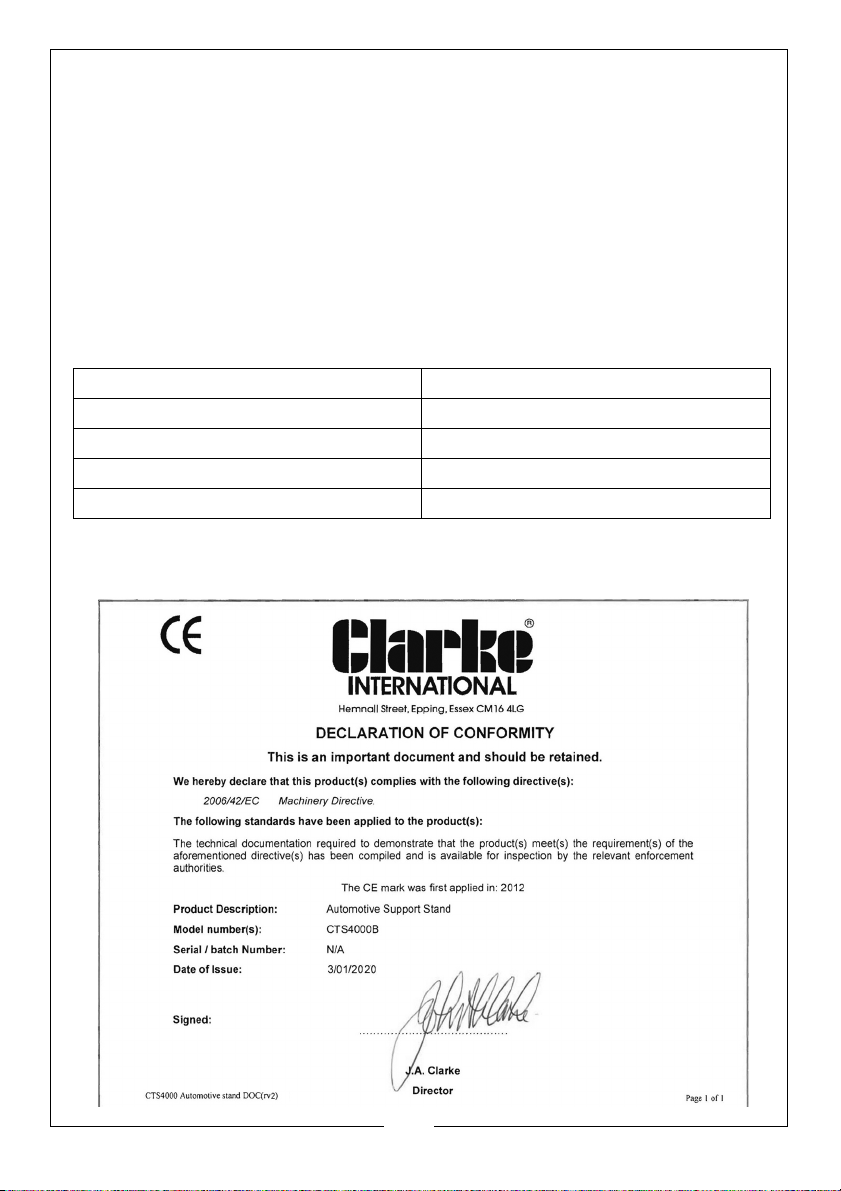
DECLARATION OF CONFORMITY
D
4
Parts & Service: 020 8988 7400 / E-mail: [email protected] or [email protected]
 Loading...