

Page 1
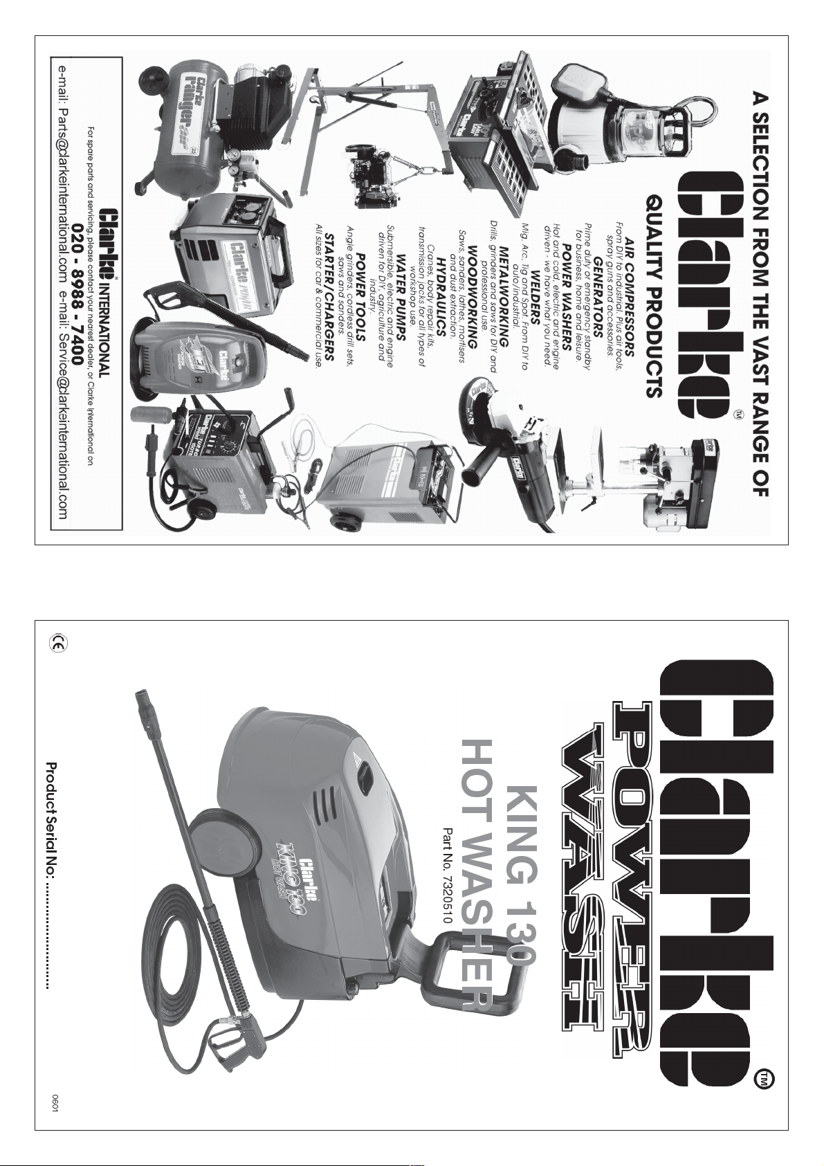
OPERATING & MAINTENANCE
INSTRUCTIONS
Product Serial No: ............................
HOT WASHER
HOT WASHER
KING 130
KING 130
Part No. 7320510
0601
Page 2
2
Please note that the details and specifications contained herein, are correct at the time of going to
For Spare Parts and Service,please contact your nearest dealer, or CLARKE International,
PARTS and SERVICE CONTACTS
print. However, CLARKE International reserve the right to change specifications at any time without
SPECIFICATIONS
SERVICE: Service@clarkeinternational.com
15
PARTS: Parts@clarkeinternational.com
PARTS & SERVICE F AX: 020 8558 3622
PARTS & SERVICE TEL: 020 8988 7400
or e-mail as follows:
on one of the following numbers.
prior notice. Always consult the machines data plate
Fuel Capacity ..........................................5.9 litres
Fuel Consumption ...................................2.5 litres/hr
Detergent Capacity ...............................6 litres
Dimensions ...............................................920X480X590MMmm
Hot Wash Operating Temp. ................... 90
Water Flow Rate ......................................7.5 l/min
c
Max. Pump Pressure ................................ 130bar
O
Fuse Rating...............................................13Amps
Noise Level ...............................................73dBA
Motor ........................................................230V 50hz
Power Rating ...........................................2.6kW
Page 3
Additives are not being
supplied
Motor cuts out
not start
Motor hums when
switched on and does
when switched on
Motor does not start
Oil leakage
Pressure fluctuations or
pressure drop
Pressure drop
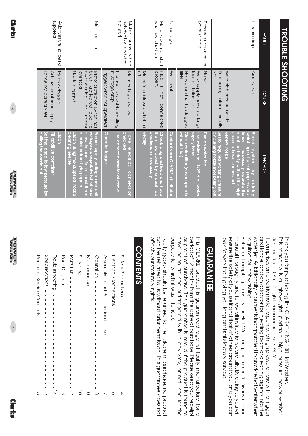
TROUBLE SHOOTING
FAULT CAUSE REMEDY
machine briefly without the high
switching off pistol grip several
times. If necessary operate the
Air in system
Bleed system by quickly
Worn high pressure nozzle.
Pressure regulator incorrectly
set
No water
Water supply hose too long/
too small diameter
No water due to clogged
filter
Worn seals
Plug is not connected
properly.
Mains fuse blown/switched
off
Mains voltage too low
Incorrect dia cable resulting
in voltage drop
Trigger Switch not operated
Motor protection switch has
been activated due to
overheating or motor
overload
Nozzle clogged
Injector clogged
Additive container empty
Lance not correctly set
14
pressure hose connected.
Renew nozzle
Set to required working pressure
by pushing nozzle in or pulling out
Turn on water tap
Use minimum 1/2" dia. water
supply hose
Clean water filter (never operate
without filter)
Contact your CLARKE distributor
Check plug and lead and have
them replaced by a qualified
electrician if necessary
Rectify
Have electrical connection
checked
Use correct diameter of cable
Operate trigger
Ensure supply voltage and unit
voltage are equal. Switch off and
allow to cool for at least three
minutes before trying again.
Clean using the supplied nozzle
cleaning needle
Clean
Fill additive container
Set the lance to low pressure by
pulling the nozzle out
This CLARKE product is guaranteed against faulty manufacture for a
period of 12 months from the date of purchase. Please keep your receipt
as proof of purchase. This guarantee is invalid if the product is found to
have been abused or tampered with in any way, or not used for the
purpose for which it was intended.
Faulty goods should be returned to their place of purchase, no product
can be returned to us without prior permission. This guarantee does not
effect your statutory rights.
CONTENTS
Safety Precautions ....................................................................... 4
Electrical Connections................................................................. 6
Assembly anmd Preparation for Use .......................................... 7
Operation ...................................................................................... 8
Maintenance .............................................................................. 10
Servicing ...................................................................................... 10
Parts List ....................................................................................... 12
Parts Diagram ............................................................................. 13
Troubleshooting .......................................................................... 14
Specifications ............................................................................. 15
Parts and Service Contacts....................................................... 15
3
GUARANTEE
look forward to it giving you long and satisfactory service.
Thank you for purchasing this CLARKE KING 130 Hot Washer.
This machine is a lightweight, portable, high pressure power washer,
designed for DIY and light commercial use ONLY
It comprises an electric motor, a pump, a high pressure hose with a trigger
and lance, and an adaptor for injecting foam or cleaning agents into the
water jet. Additionally, a burner is incorporated to provide hot water when
required for hot washing.
Before attempting to use your Hot Washer, please read this instruction
manual thoroughly and follow all instructions carefully. By doing so you will
ensure the safety of yourself and that of others around you, and you can
Page 4
13. When not in use, disconnect from the water and electrical supplys,
and ensure the system is completely drained. Store in a dry, frost free
environment.
12. We recommend the use of safety goggles when using machine in
paint hinners, petrol, oil, etc.
any application where loose particles of stone or grit etc. may be
blown around by the high pressure spray.
tower or scaffolding.
9. Never use the chemical injection facility to introduce solvents e.g..
10. Do not operate the machine whilst standing on ladders: use a platform
11. Children should not be allowed to use the machine.
5. Never operate the machine with any of the covers removed.
7. Never supply any liquid other than water to the water inlet.
8. Use only chemical cleaning agents (detergents) approved for power
washing when using the chemical injection facility.
6. Do not, attempt any electrical or mechanical repair. If you have a
trigger. Do not attempt to disconnect any hose or coupling with
problem with your machine contact your local dealer or Clarke
Customer Services Dept., tel: 020 8988 7400
pressure still in the hose.
4. After use, and before disconnecting
hoses, release the pressure in the
high pressure hose by operating the
3. Never direct the spray jet at the
pressure nozzle.
machine itself or any other electrical
equipment.
thoroughly reliable and completely familiar with the safety precautions.
NEVER allow anyone to operate this equipment unless they are
damage to persons or property if subject to misuse.
Water at high pressure can be dangerous and may cause severe
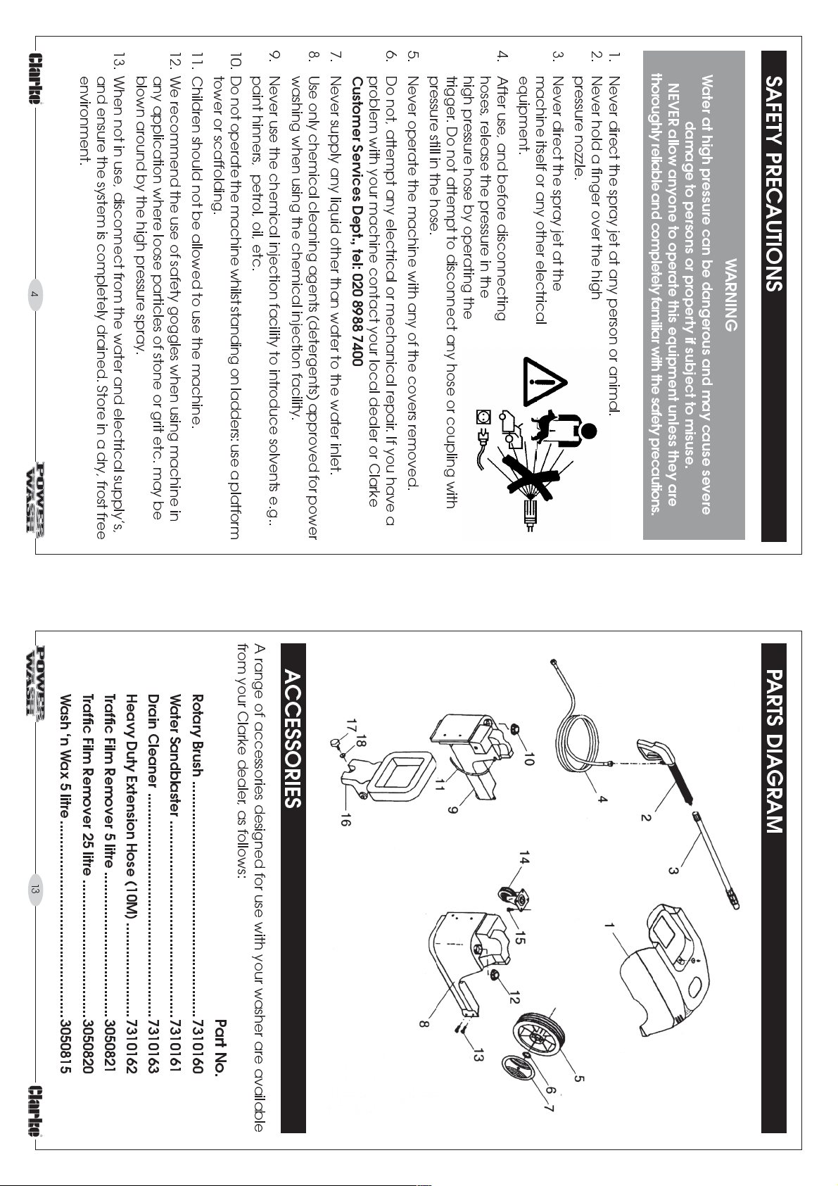
SAFETY PRECAUTIONS
1. Never direct the spray jet at any person or animal.
2. Never hold a finger over the high
WARNING
4
13
Traffic Film Remover 25 litre ...................................3050820
Wash n Wax 5 litre..................................................3050815
Heavy Duty Extension Hose (10M) ........................7310162
Traffic Film Remover 5 litre .....................................3050821
Water Sandblaster ..................................................7310161
Drain Cleaner .........................................................7310163
Rotary Brush ............................................................7310160
Part No.
A range of accessories designed for use with your washer are available
from your Clarke dealer, as follows:
ACCESSORIES
PARTS DIAGRAM
Page 5
SERVICE: Service@clarkeinternational.com
PARTS: Parts@clarkeinternational.com
PARTS & SERVICE F AX: 020 8558 3622
PARTS & SERVICE TEL: 020 8988 7400
For Spare Parts and Service,please contact your nearest dealer , or CLARKE International,
PARTS and SERVICE CONTACTS
16 Handle Assy 1 FP85030100
17 Securing Screw D25 1 FP14802300
18 Washer M6x24 1 FP12900900
13 Screw M6x15 4 FP10108100
14 Castor 1 FP17804000
15 Screw M6x15 4 FP10108100
12 Detergent Filler Cap 1 FP18106200
9 Fuel Tank 1 FP85030500/A
10 Fuel Filler Cap 1 FP18106200
11 Fuel Hose - Clear Plastic 1 FP15609700
5 Wheel 2 FP17804400
6 Retaining Clip 2 FP17802600
7 Trim 2 FP17805000
8 Detergent Tank 1 FP85030600/A
2 Gun. 1 FP65002300
3 Lance Extension with nozzle 1 FP62105700
4 Hose Standard 1 FP68502200
Item Description Qty Part No.
1 Cover 1 FP85032100
PARTS LIST
or e-mail as follows:
12
on one of the following numbers.
14. Disconnect from the mains supply before carrying out any
If the machine must be used in an enclosed area, ensure the burner
All venting must be in accordance with applicable laws and local
exhaust is vented to the outside atmosphere.
ordinances for such installations.
IMPORTANT:
5
may be present.
adequate ventilation, or in
areas where flammable
vapours (Petrol, solvents etc.),
18. DO NOT operate the
become very hot. It is
strongly advised that a good
pair of industrial gloves be
worn.
machine indoors or in
enclosed areas without
17. Take care when handling the
the fuel tank.
lance when hot washing.
The metal components can
16. Observe all precautions
regarding the use of
flammable liquids when filling
15. Never pull the washer by the power cable, or yank the cable it to
maintenance or servicing.
disconnect from the socket. Keep the cable away from heat, oil or
sharp edges.
Page 6
IF IN DOUBT, CONSULT A QUALIFIED ELECTRICIAN.
Do not attempt any electrical repairs yourself.
6
If an extension cable is used, always ensure it is fully unwound. When used
outdoors, ensure the extension cable is specifically designed for outdoor use.
The maximum extension length is 25 metres. Ensure that the wire sizes in the cable
are at least 2.5mm
thicker than the cable supplied with the washer.
EXTENSION CABLES
4. Replacement fuse covers can be obtained from your local dealer or most
electrical stockists.
2. Never use the plug without the fuse cover fitted.
3. Should you wish to replace a detachable fuse carrier, ensure that the correct
replacement is used (as indicated by marking or colour code).
danger of electric shock if it is subsequently inserted into a socket outlet.
If this appliance is fitted with a plug which is moulded onto the electric cable (i.e.
non-rewireable) :
1. The plug must be thrown away if it is cut from the electric cable. There is a
IMPORTANT:
2
in cross section. As a general rule, the extension cable must be
As the colours of the wires in the mains lead may not correspond with the coloured
We recommend that this machine is connected to the mains supply through a
The fuse in the plug must ASTA approved to BS1362and rated at
Residual Current Device (RCD).
markings identifying the terminals in your plug, proceed as follows:
in accordance with the following colour code:
his product is provided with a standard 13 amp, 230 volt (50Hz), BS 1363 plug, for
T
connection to a standard, domestic electrical supply.
Should the plug need changing at any time, ensure that a plug of identical
specification is used. IMPORTANT: The wires in the mains lead should be wired up
ELECTRICAL CONNECTIONS
Connect GREEN & YELLOW coloured cord to plug terminal marked
with a letter E or Earth symbol .
Connect BROWN coloured cord to plug terminal marked letter L
FUSE RATING
13 amps
Connect BLUE coloured cord to plug terminal marked letter N
Green & Yellow ................ Earth
Blue ....................................Neutral
Brown.................................Live
WARNING: THIS MACHINE MUST BE EARTHED.
Should you find it necessary
to adjust the mixture
strength, first ensure the
machine is switched OFF
and unplugged from the
mains supply, although, if
the burner has bennused,
run for at least 3 minutes at
the cold setting to ensure
the boiler is cold before
doing so.
Remove the top cover and
test the boiler top ensure it is
cold.
Locate the knurled adjuster ring nut, arrowed in Fig. 5 which is located on
the Detergent Tank side of the machine.
Turning the Ring Nut clockwise, from the position shown in Fig. 5, will
decrease the mixture strength - similarly, screwing in an anticlockwise
direction will incr ease mixture strength. Reassemble the machine and test.
If more adjustment is required....repeat the operation, remembering to
switch OFF and unplug the machine before removing the cover.
Dept. when de-sooting is required.
Poor grades of fuel oil or inadequate combustion will cause heavy build
up of soot on the heating coil. This deposit will insulate the coil and reduce
efficiency. It will restrict air flow through the coil, further aggravating the
soot build up. Contact your CLARKE dealer or CLARKE International Service
4. Detergent Mixture Strength
11
contaminated water in the water tank.
3. Soot Build up
2. Limescale
Periodically, check the heating coil for limescale buildup. This will be
dependant upon the relative hardness of your water supply.
When de-scaling is required, use a large water tank as your water supply
and add de-scaler according to the manufacturers instructions.
Remove the lance extension from the handle assembly, place the handle
assembly in the water tank, with the trigger held in the depressed position
by some means, and run the pump and heater for approx. 40 mins.
When completed, switch off the heater, and flush out the system with
clean water by connecting to a water supply or replacing the
Fig.5.
Page 7
Operate the lance trigger once more to ensure there is no pressure in the
high pressure hose. NEVER disconnect High pressure hose without operating
Store the Hot Washer in an horizontal position, preferably under cover,
protected from the elements.
If there is a danger of freezing, the pump should be filled with antifreeze
by inserting the inlet and outlet hoses into a bucket of antifreeze as shown
in Fig.4. Start the machine and allow the antifreeze to circulate. After a
short time stop the machine using the procedure outlined on page 8,
and store the machine with the antifreeze still within the pump body.
SERVICING
1.Oil burner
It is recommended that the oil burner be serviced yearly, or as needed
depending upon the machines usage. Please contact the CLARKE
International Service Dept. on 0208 8988 7400
10
cables over the hot exhaust.
STORAGE
AFTER EACH USE
adjustment, servicing or maintenance.
Ensure the plug is removed from the socket before carrying out any
WARNING:
MAINTENANCE
When using chemical detergents, always ensure the system is thoroughly
flushed out after use as described
in Shutting Down The Machine on
page 8
.
Ensure the hoses and power cable
are coiled and properly stowed. DO
NOT allow them to be left casually,
in a heap. This invites damage and
will cause rapid deterioration. Take
care NOT to drape the hoses/
trigger.
Fig.4.
The machine is fully assembled except for the handle which is hinged
and lies flat for transit purposes. Raise the handle and secure in position
with the screw provided on the rear of the machine (A, Fig.1).
The lance is assembled by screwing the two sections together. Screw one
end of the high pressure hose to the lance, and the other to the high
pressure outlet , shown at D, fig. 1
A 3/4 BSP adapter with a 1/2 hose connector is provided at the ,low
pressure water inlet, shown at E,, Fig.1. A suitable hose (not supplied), may
be attached, with a worm drive clip (not supplied), and connected to
your water supply. Alternatively, quick fit couplings, which are readily
If you intend to use the chemical injection facility, fill the detergent tank
with the requisite detergent. The Detergent Tank Filler Cap is shown at B,
Fig.1.
Use ONLY those detergents specifically designed for use with Power
Washers. We recommend the use of CLARKE Traffic Film Remover, which is
a powerful low foaming agent for car cleaning, patio cleaning etc., or
CLARKE Wash & Wax, both available from your CLARKE dealer.
paraffin, but
IMPORT ANT:Before use, ensure the water supply is of adequate volume for your needs,
e.g., if you use a water butt - ensure it contains sufficient water.
Unscrew the fuel filler cap (C, Fig.1), and fill the tank with diesel fuel or
available from most hardware or DIY stores, may be used.
ASSEMBLY AND PREPARATION FOR USE
DO NOT mix them.
WARNING: DO NOT USE PETROL
7
Fig.1.
Page 8
HIGH and LOW PRESSURE is set be pulling IN or pushing OUT the nozzle as
shown in Fig. 2
IN -HIGH pressure OUT - LOW pressure
either side of the pump, thereby reducing the load on the motor when
restarting.
NEVER attempt to run the machine with the water supply disconnected
or turned off.
subsequent restarting of the motor as pressure will remain equalised on
safety latch to prevent it from being pulled. This will ease and assist the
its use after a few minutes or so, DO NOT depress the trigger, but set the
In the event that you switch the machine OFF but intend to continue with
nearby wall etc.
Make certain the PUMP ON/OFF switch mounted on top of the unit, is set
in the OFF position.
The ON/OFF switch is the front of the two switches mounted on the top
panel as shown in fig. 1, and is identified by the symbol
Connect the plug to the mains supply, preferably via a Residual Current
Device.
Turn the water tap fully on.
When starting, it is
In order to ease the starting process, and to prevent the possibility of blown
fuses, pull the trigger on the lance - it may be necessary to release the
safety latch in order to do so.
Hold the trigger in that position whilst switching the pump ON, and allow
the pump to develop full pressure.
You may release the trigger once full pressure is developed.
aimed at an area where the water jet will cause damage. i.e. away
that splash back could also cause damage if the jet is trained on a
from people, animals, windows - greenhouses etc., and be aware
In addition, care must be taken to ensure that the nozzle is NOT
held firmly.
athigh pressure can cause the lance to kick it should therefore be
Ensure the operator is aware that when the trigger is pulled, water
WARNING
IMPORTANT
that you adopt the following procedure:
A. COLD WASH
OPERATION
Additionally a FAN SPRAY may be
used by twisting the nozzle as
If the burner has been used, switch it OFF by pressing the rocker switch on
top of the unit.
If the chemical injection facility has been used, turn the pressure adjuster
on the end of the lance to HIGH pressure, and allow the pump to run for
a minute or so until the water being ejected is cold and foam free, then
switch OFF the pump.
Disconnect fr om the mains electrical supply, and turn OFF the water supply
- disconnect where appropriate.
C. SHUTTING DOWN THE MACHINE
98
near the unit during hot wash operations.
B. HOT WASH
Follow the same procedure as for the cold wash, but switch the burner ON
once the pump has been switched ON, by pressing the rear rocker switch
on top of the unit, marked ON/OFF, and identified by the symbol.
Take care when using the HOT WASH facility. DO NOT forget that certain
components get extremely hot during operation, and will remain so for a
period after switching OFF. DO NOT allow anyone, particularly children,
instructions regarding the use of chemical detergents
: Ensure you read and
Detergents will automaticlly be
drawn andf mixed with the water
jet when the nozzle is set to LOW
PRESSURE.
NOTE: The detergent facility will
ONLY operate at LOW PRESSURE
Mixture strength is factory set but
may be adjusted by following the
instructions under Maintenance.
IMPORTANT
comply with the manufacturers
shown in Fig.3.
USING DETERGENTS
Fig.2.
Fig.1.
 Loading...