

Page 1
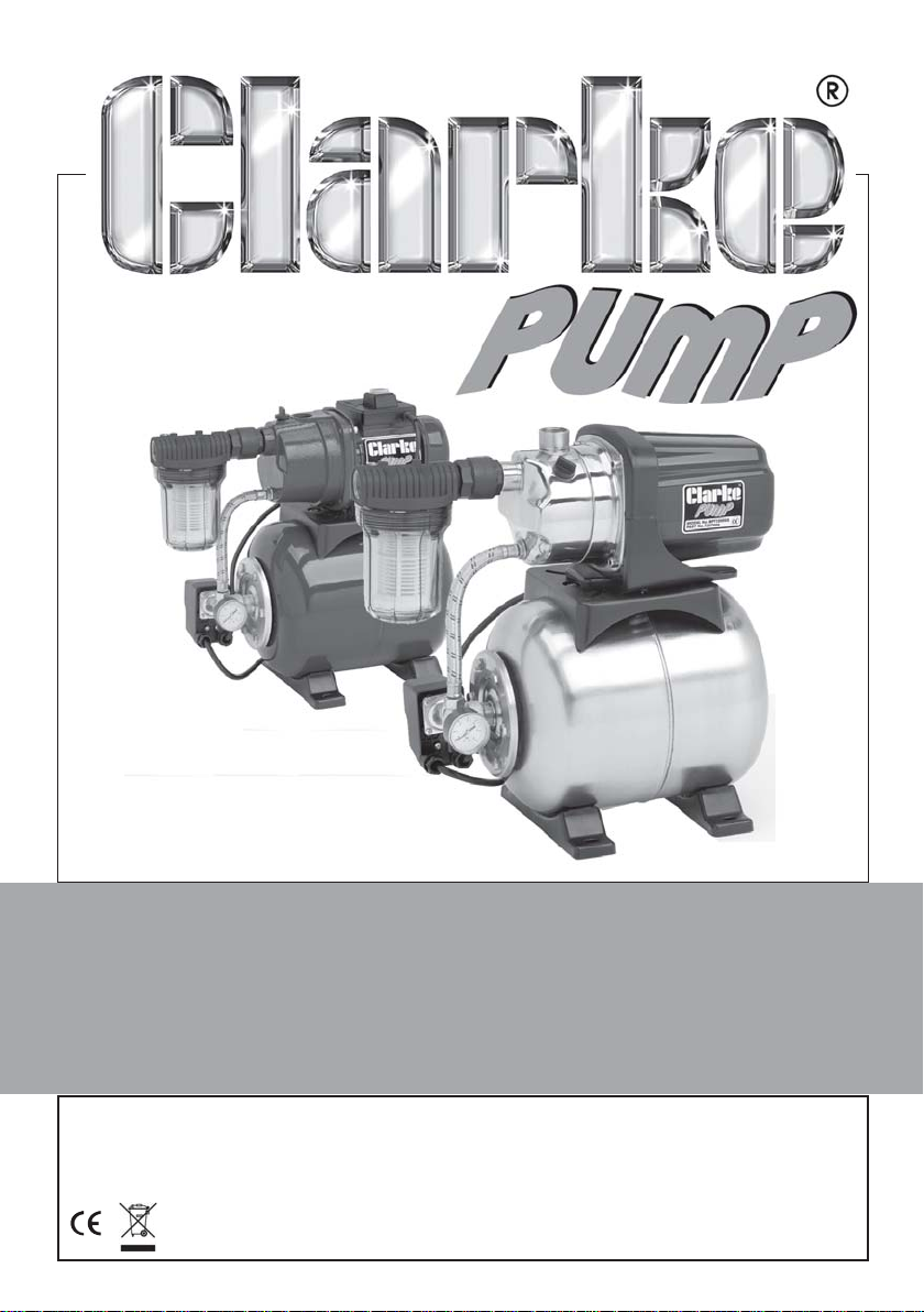
BOOSTER PUMPS
Models Nos: BPT600 & BPT1200SS
Part Nos: 7237004 & 7237006
OPERATING & MAINTENANCE
INSTRUCTIONS
GC1011rev2a
Page 2
INTRODUCTION
Thank you for purchasing this CLARKE Booster Pump.
Before attempting to operate the pump, it is essential that you read this
manual thoroughly and carefully follow all instructions given. In doing so you
will ensure the safety of yourself and that of others around you, and you can
also look forward to the pump giving you long and satisfactory service.
GUARANTEE
This CLARKE product is guaranteed against faulty manufacture for a period of
12 months from the date of purchase. Please keep your receipt as proof of
purchase.
This guarantee is invalid if the product is found to have been abused or
tampered with in any way, or not used for the purpose for which it was
intended.
Faulty goods should be returned to their place of purchase, no product can
be returned to us without prior permission.
This guarantee does not effect your statutory rights.
ENVIRONMENTAL PROTECTION
Do not dispose of this product with general household waste. All tools,
accessories and packaging should be sorted, taken to a recycling
centre and disposed of appropriately.
PARTS & SERVICE
For parts & Servicing, please contact your nearest dealer, or
CLARKE International, on one of the following numbers.
PARTS & SERVICE TEL: 020 8988 7400
PARTS & SERVICE FAX: 020 8558 3622
or e-mail as follows:
PARTS: [email protected]
SERVICE: [email protected]
2
Page 3

CONTENTS
Introduction ............................................................................................ 2
Guarantee .............................................................................................. 2
Environmental Protection ...................................................................... 2
Parts & Service ....................................................................................... 2
Table of Contents ................................................................................... 3
Description ............................................................................................. 3
General Safety Precautions .................................................................. 4
Electrical connections .......................................................................... 6
Preparation for Use ................................................................................ 7
Operation ............................................................................................. 10
Maintenance ........................................................................................ 11
Troubleshooting.................................................................................... 12
Technical Specification....................................................................... 14
Accessories .......................................................................................... 14
Parts Lists and Diagrams ..................................................................... 15
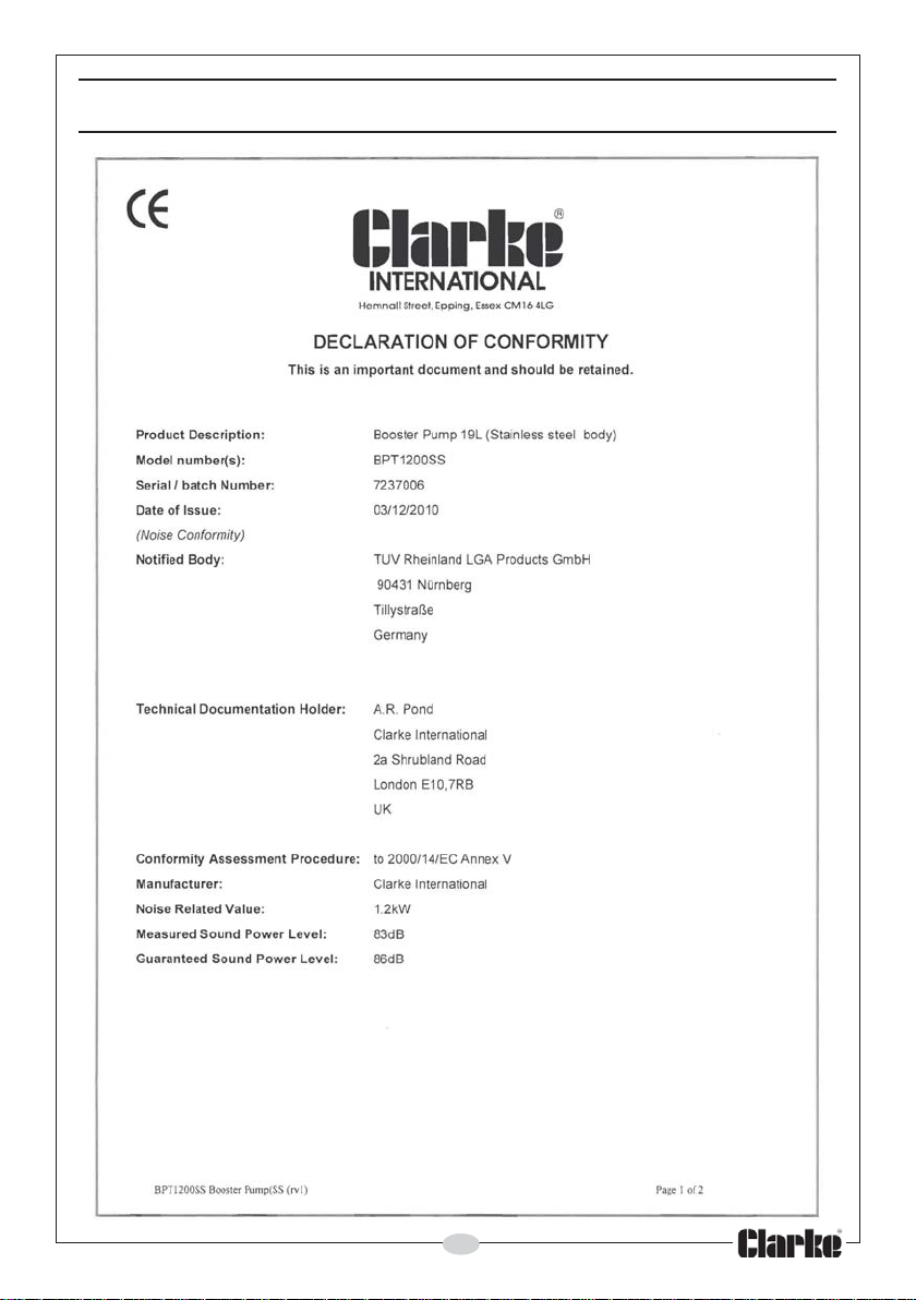
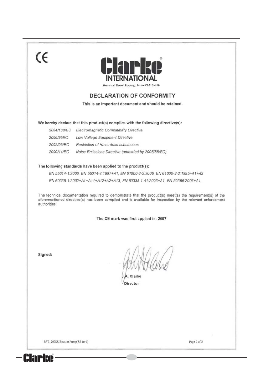
Declaration of Conformity .................................................................. 19
DESCRIPTION
The BPT600 and BPT1200SS are centrifugal, horizontal, electric pumps with a
self-priming capability and are designed with a venturi system, suitable for
pumping water from up to 35 m height (BPT600) / 46 m height (BPT1200SS).
They are designed to operate with clean water only at a maximum
temperature of 35°C. Operating with contaminated or salt water should be
avoided. The inlet of the pump is higher than the inlet of the impeller so that
the pump can start operating when only the body is filled with water.
The inlet side of the pump should always be fitted with a one-way valve to
prevent water syphoning back out of the pump and to ensure the pump is
always primed for the next start-up.
The pressure tank incorporates a butyl membrane, and a pressure controller
provides automatic stop/start control. The pumps are supplied with a 1”BSP
inlet filter with easy to clean replaceable elements. The transparent filter
bowl allows for a visual check as to the condition of the filter cartridge.
Upon receipt, any damage or deficiency should be reported to your CLARKE
dealer immediately.
3
Page 4

GENERAL SAFETY PRECAUTIONS
As with all machinery, there are certain hazards involved with its
operation and use. Exercising caution will reduce the risk of
personal injury .
WORK AREA
1. Keep the work area clean and well lit. Floors should always be kept clear.
Cluttered or dark areas invite accidents.
2. Keep children and bystanders away while operating machines.
Distractions can cause loss of control.
PERSONAL SAFETY
1. ALWAYS stay alert, watch what you are doing and use common sense
when operating this pump. Do not use the pump while you are tired or
under the influence of medication, drugs or alcohol. A moment of
inattention can result in personal injury.
2. Do not over-reach. Keep your proper footing and balance at all times
when positioning the pump.
3. NEVER direct the water discharge towards electrical wiring or equipment.
4. ALWAYS store the pump out of reach of children and do not allow persons
unfamiliar with these instructions to operate it.
5. NEVER direct the discharge flow towards another person.
6. ALWAYS thoroughly familiarise yourself with this pump & its operation, and
follow all instructions in this manual.
7. ALWAYS ensure that the pump is properly positioned to prevent it from
moving during operation, and that the immediate area surrounding the
pump is kept clear.
GENERAL EQUIPMENT USE AND CARE
WARNING: The BPT600 & BPT1200SS pumps are not submersible
pumps. On no account should they ever be immersed in water.
1. ALWAYS maintain the pump with care and keep it clean.
2. NEVER use this pump if any part is damaged. Have it inspected and
repaired by your local Clarke dealer.
3. NEVER modify this pump in any way. Use it ONLY for the purpose for which
it is designed.
4. NEVER run the pump dry. Always ensure the pump is filled or ready to be
filled with water before starting.
4
Page 5

5. NEVER overtighten drain or filler plugs. Excessive force may damage the
threads and make the plug difficult to remove in future.
6. ALWAYS ensure the pump is in a horizontal position and is firmly anchored
via its fixing screws to a level surface.
7. NEVER use for pumping flammable liquids or corrosive chemicals. These
pumps are designed to pump WATER ONLY.
8. ALWAYS use a strainer connected to the suction (inlet) hose, to prevent
stones and other solids from being drawn up, which could cause damage
to the pump.
SERVICING
1. ALWAYS have the pump serviced by your local CLARKE dealer, using only
identical replacement parts. This will ensure the safety of the pump is
maintained. The use of non standard parts could be hazardous.
2. NEVER attempt any repairs yourself. If you have a problem with the pump
contact your local CLARKE dealer.
3. ALWAYS turn the pump off before carrying out any maintenance.
Your CLARKE water pump has been designed to give long and trouble free
service. If, however, having followed the instructions in this booklet carefully,
you encounter problems, take the unit to your local CLARKE dealer.
5
Page 6
ELECTRICAL CONNECTIONS
WARNING! Read these electrical safety instructions thoroughly
before connecting the product to the mains supply.
Before switching the machine on, make sure that the voltage of your
electricity supply is the same as that indicated on the rating plate. This
product is designed to operate using 230 VAC mains power. Connecting it to
any other power source may cause damage.
This product may be fitted with a non-rewireable plug. If it is necessary to
change the fuse in the plug, the fuse cover must be refitted. If the fuse cover
becomes lost or damaged, the plug must not be used until a suitable
replacement is obtained.
If the plug has to be changed because it is not suitable for your socket, or
due to damage, it should be cut off and a replacement fitted, following the
wiring instructions shown below. The old plug must be disposed of safely, as
insertion into a mains socket could cause an electrical hazard.
WARNING! The wires in the power cable of this product are
coloured in accordance with the following code:
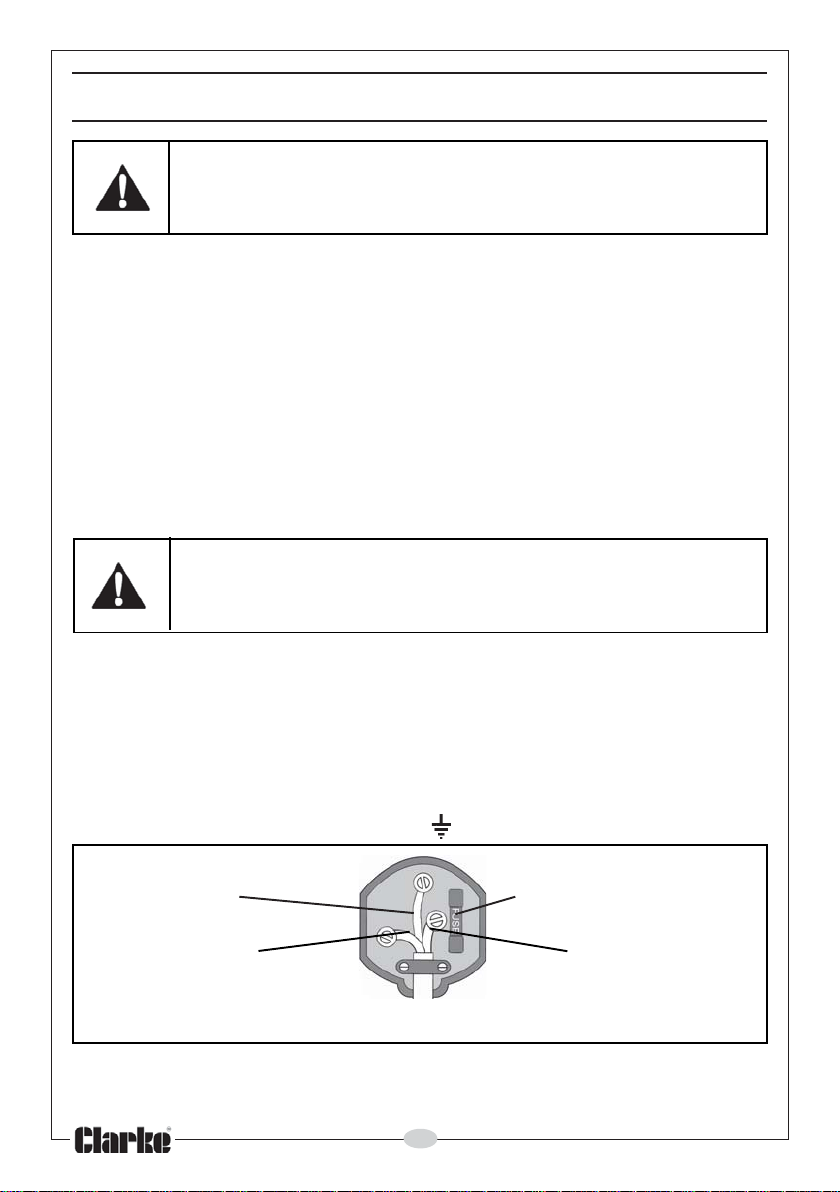
Blue = Neutral Brown = Live Yellow and Green = Earth
If the colours of the wires in the power cable of this product do not
correspond with the terminal markings of your plug, proceed as follows.
• The wire which is coloured Blue must be connected to the terminal
which is marked N or coloured Black.
• The wire which is coloured Brown must be connected to the
terminal which is marked L or coloured Red.
• The wire which is coloured Yellow and Green must be connected to
the terminal which is marked E or or coloured Green.
Plug must be BS1363/A approved
Earth Always fit a 13 Amp fuse.
(Green and Yellow)
Neutral Live
(Blue) (Brown)
Ensure that the outer sheath of the cable is firmly held by the clamp
We strongly recommend that this machine is connected to the mains supply
via a Residual Current Device (RCD).
If in doubt, consult a qualified electrician. DO NOT attempt repairs yourself.
6
Page 7
PREPARATION FOR USE
Accessories designed specifically for this range of pumps are available from
your nearest CLARKE dealer. Contact your CLARKE dealer for further
information, or CLARKE International Sales Department on 01992 565333.
IMPORTANT: The pump MUST NOT be connected to the mains electrical supply
until all hose/pipe installation is completed.
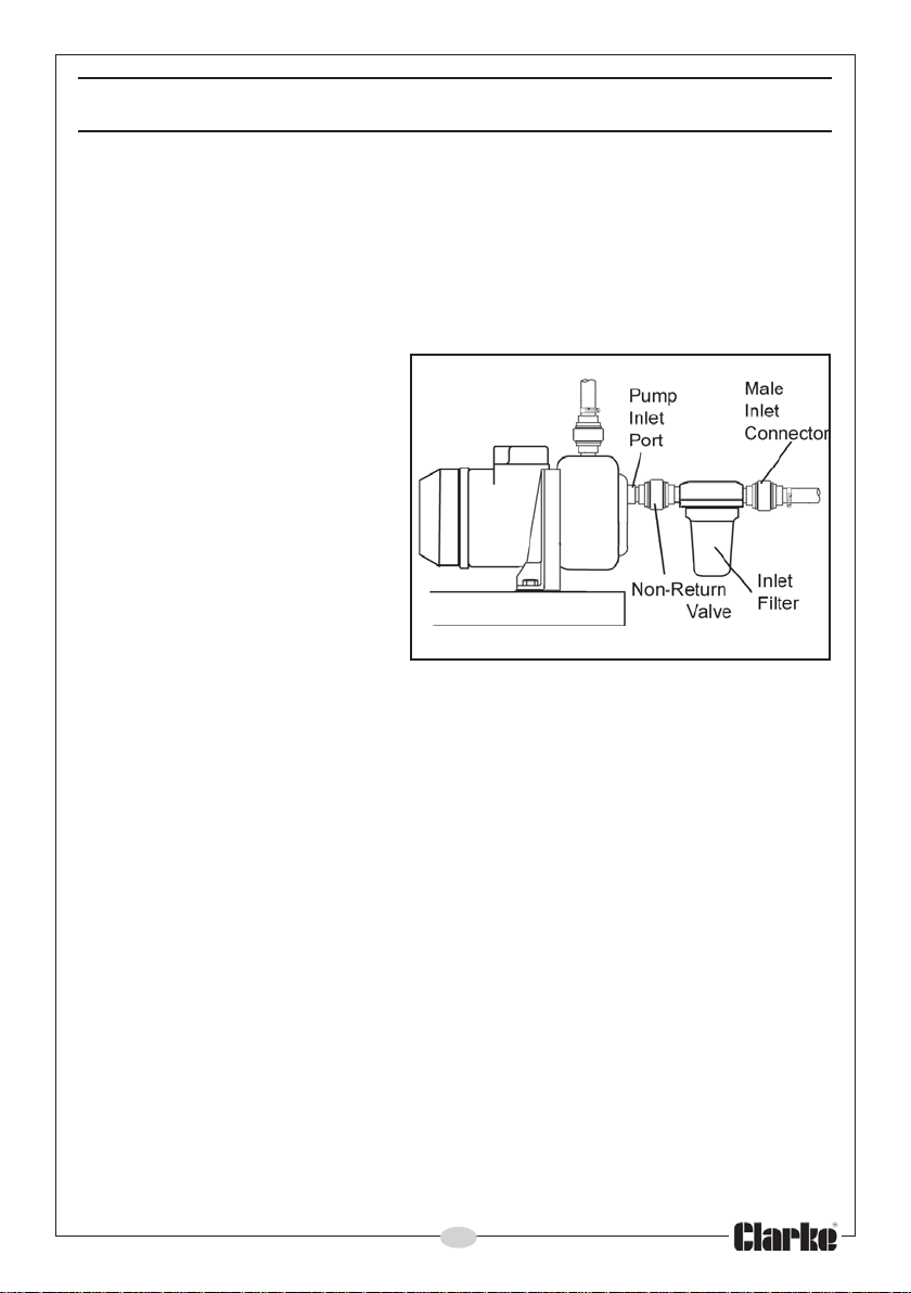
CONNECTING THE INLET FILTER (FIG 1)
1. Screw a non-return valve to
the pump inlet ensuring it is
the right way round, ie, with
the spring-loaded valve
able to pass water in the
direction of flow. Do not
overtighten.
2. Screw the inlet filter onto the
non-return valve and
tighten by hand. Do not
overtighten.
• Ensure the moulded
arrow in the filter body
which indicates the
direction of flow, is pointing towards the pump and that the bowl is
hanging vertically down. The filter bleed plug should be seen at the
inlet side of the filter.
3. Screw the male inlet connector into the filter inlet port and hand tighten.
Fig. 1
POSITIONING THE PUMP
A typical installation of the pump is shown in Fig 1. An air-tight seal is essential
when connecting the suction and discharge hoses to the pump.
• Ensure there is no damage to the hoses which must be well
protected and well supported.
• The pump must always be installed and operated in a horizontal
position i.e. with the outlet port facing vertically upwards.
• The fixing holes in the feet should be used to secure the pump firmly
in its operating position.
• Always ensure there is adequate air circulation around the pump
motor.
• Avoid situations where the pump could become drenched with
water. Neither the motor or terminal box are designed to be
waterproof.
7
Page 8
• Position the pump as near to the water source as possible.
• Ensure there is adequate drainage and there is no risk of damage
to property as a result of water being discharged.
• The performance of your pump will be affected by the diameter of
the inlet pipe - any restriction will greatly reduce the flow. We
strongly recommend that you use as large a pipe diameter as
practical.
• A gate valve may be installed on the delivery (outlet) side of the
pump which can be adjusted as required to regulate the flow of
water and can also assist in priming the pump.
CAUTION: DO NOT PLACE ANY RESTRICTION ON THE SUCTION (INLET)
SIDE OF THE PUMP UNLESS IT IS AN ISOLATOR VALVE IN A GRAVITY FED
SYSTEM. THESE PUMPS SHOULD NOT BE OPERATED WITH THE DELIVERY
VALVE COMPLETELY CLOSED.
• To prevent unnecessary strain or possible distortion to the pump,
ensure that adequate support is provided to the hoses/pipes. They
will be considerably heavier when filled with water.
• Where the pump is to be a permanent fixture, the fittings to the
pump must be flexible, i.e. a short piece of hose should be installed
between the rigid pipework and the pump.
IMPORTANT: An air leak in the suction line will prevent priming and reduce the
capacity of the pump.
Pay particular attention to the following:
a. Keep all hoses as short and straight as possible and avoid sharp
bends.
b. Ensure there is adequate drainage for the discharged water.
c. If a flexible hose must be laid across a roadway, protect it with
planking.
(Instantaneous shut off pressure, applied when a vehicle runs across an
unprotected hose, could cause “hydraulic shock”, which can damage the
pump and/or the hose).
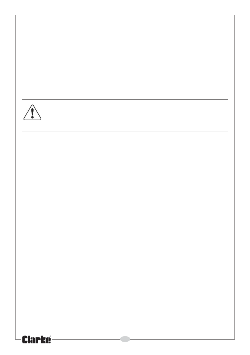
USING A FOOT VALVE/FILTER
Instead of using the pump for boosting an existing water supply,the pump
may typically be used for drawing raw water from a well or excavation. In
these applications a foot valve/coarse filter should be fitted to the lower end
of the suction hose as illustrated in Fig 2. This will retain water in the suction
system and more importantly, to prevent the possibility of large objects
entering the pump body.
8
Page 9
1. Attach the foot valve to the end of the suction
hose to prevent stones etc, from being drawn
up, which could cause damage to the pump.
Keep the foot valve clean. If it is likely to clog
with dirt or debris, proceed by either:
a. Preparing a bed of stones on which to rest the
foot valve.
b. Position the valve so that it stays clear of the
bottom of the pit, pond or excavation.
c. Tie the foot valve inside a basket or bucket.
Foot
Valve
Filter
PREPARING THE BOOSTER PRESSURE TANK
Fig. 2
These pumps utilise an air pressure tank with a pressure regulator to provide a
constant pressure at the outlet. The pump will automatically cut in when the
water pressure reduces to 1.5 Bar, and cut out when the pressure reaches 3
Bar. These pressures are factory set and must not be altered. The pump may
continue to operate for a short while, after the tap is turned off, until the cutout pressure is reached.
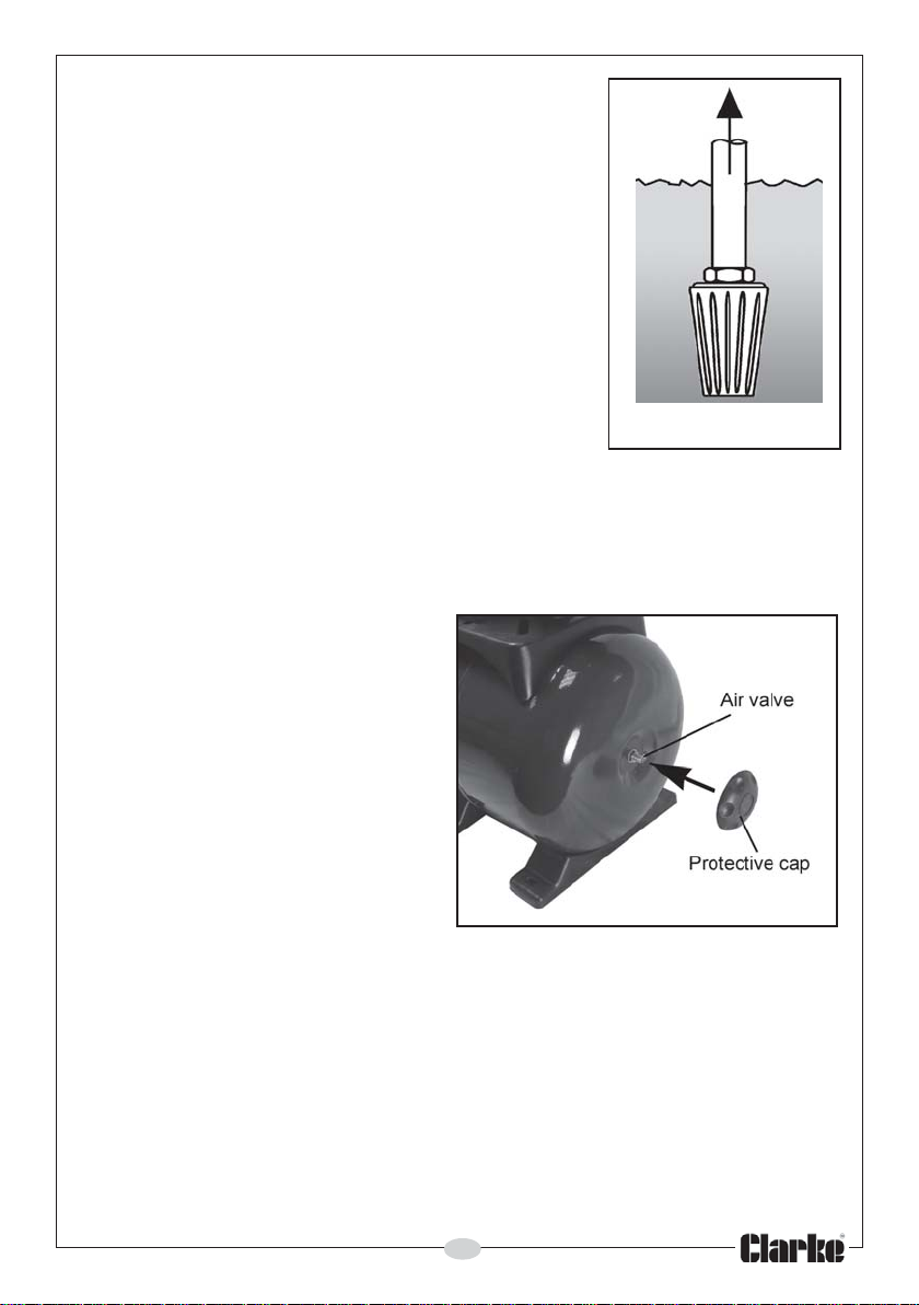
In order for the system to operate
correctly, it is necessary to pressurise
the air chamber to 1.5 Bar (22psi),
which is carried out as follows:
1. Unscrew the large protective
cap on the end of the pressure
tank to reveal the air valve as
shown in Fig 3.
2. Use an airline or foot pump to
pressurise the tank.
3. Check the pressure with a
Fig 3
standard pressure gauge and
replace the protective cap when completed.
Important; This procedure must be carried out before connecting to the water
supply.
PRIMING THE PUMP
When suction lift is used to draw water into the pump it is essential that all
connections and hoses are completely tight or the system will not work.
Although the pump is of the ‘self-priming’ type, it is still necessary to
completely fill the inlet side of the pump with water prior to initial starting, or if
the system has been drained for any other reason. Priming is carried out as
follows.
9
Page 10
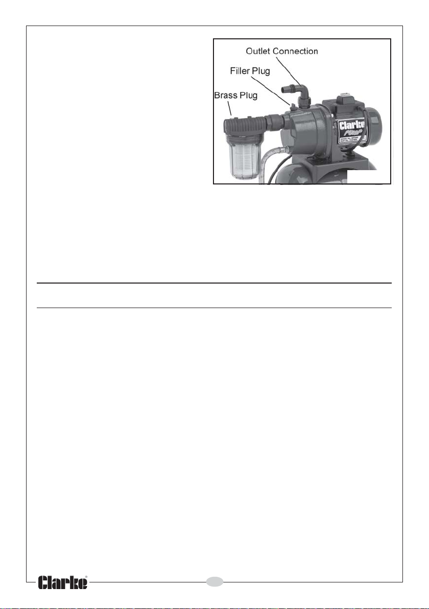
1. Remove the filler plug on top of
the pump and slowly fill with
water until all air is expelled.
• Refilling is necessary only if the
pump has been drained or if the
water has been lost. Never allow
the pump to run dry.
2. Open any valve(s) fitted to the
outlet side of the pump so as to
ensure as great a flow as
possible.
• If the inlet filter is being used, it is
recommended that you remove
the brass plug on top of the filter unit and fill the filter bowl with water.
3. Switch on the pump and check for leaks. Water should start to flow
through the system after a short while. If this does not happen, check to
ensure that:
a. the inlet pipe is completely secure and free from any defects.
b. the pump body has been correctly primed.
Fig 4
OPERATION
1. Open any valves in the pipeline.
2. Connect the power supply and switch the pump ON.
3. Wait for the pump to prime.
4. If the motor fails to start or does not deliver water, refer to Troubleshooting
on page 12.
NOTE: Filling the suction pipe with water will speed up the priming
process, and it is recommended that a non-return valve be fitted
to the end of the suction pipe.
• If debris has entered the pump causing a blockage, the end
housing can be taken off and the pump cleaned out as described
under Maintenance on page 11.
REMEMBER: Contaminated water is water containing small solids in
suspension, NOT slurry, sludge, sand, or mud.
5. Stop the pump by switching the pump OFF.
6. After use, drain residual water from the pump if there is danger of freezing.
If the pump has been used with contaminated or salty water, it should be
thoroughly flushed with clean water following use, both inside and out
before replacing the plug.
10
Page 11
MAINTENANCE
For any problems requiring the dismantling and overhaul of the pump,
contact your CLARKE International Service Department on 020-8988-7400.
THE FILTER
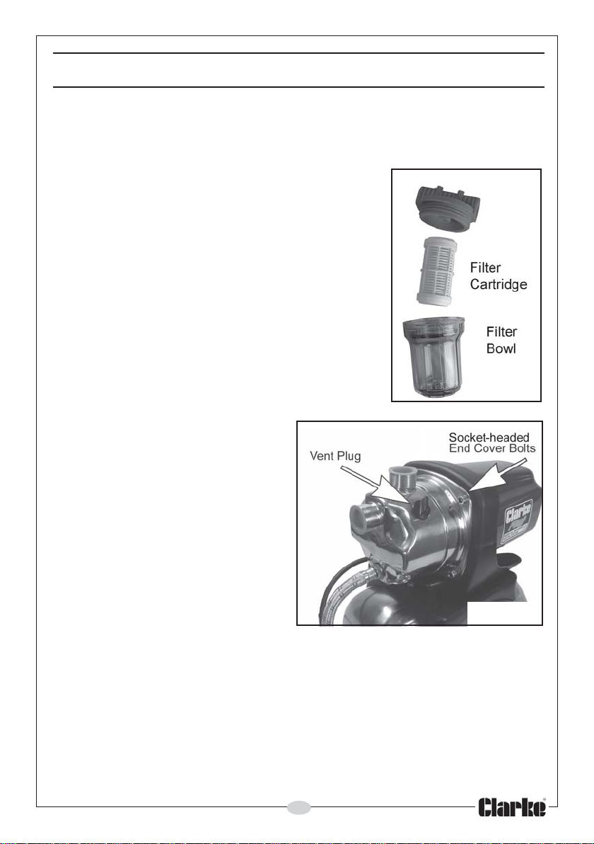
The separate inlet filter (Part number 7175100)
supplied with these pumps will need regular
cleaning out after use. Unscrew the filter bowl from
the top section as in Fig 5 and wash out the bowl
and filter element with clean, soapy water.
CLEANING
The only other maintenance required is a regular
inspection to ensure that nothing is blocking the
passage of water through the pump.
If you suspect the pump is blocked by mud, silt,
leaves etc, disconnect it from the mains power
supply and backflush to clear any blockage.
Always keep the pump in a clean
condition, checking regularly for
loose bolts or a damaged power
cable etc.
If the pump has been used under
arduous conditions leading to
internal fouling or damage, the end
cover can be removed by undoing
the four socket-headed cover bolts
shown in Fig 6. The impeller can
then be inspected for damage.
Fig 5
STORAGE
Store in a clean, dry environment
protected from the weather.
Fig 6
11
Page 12
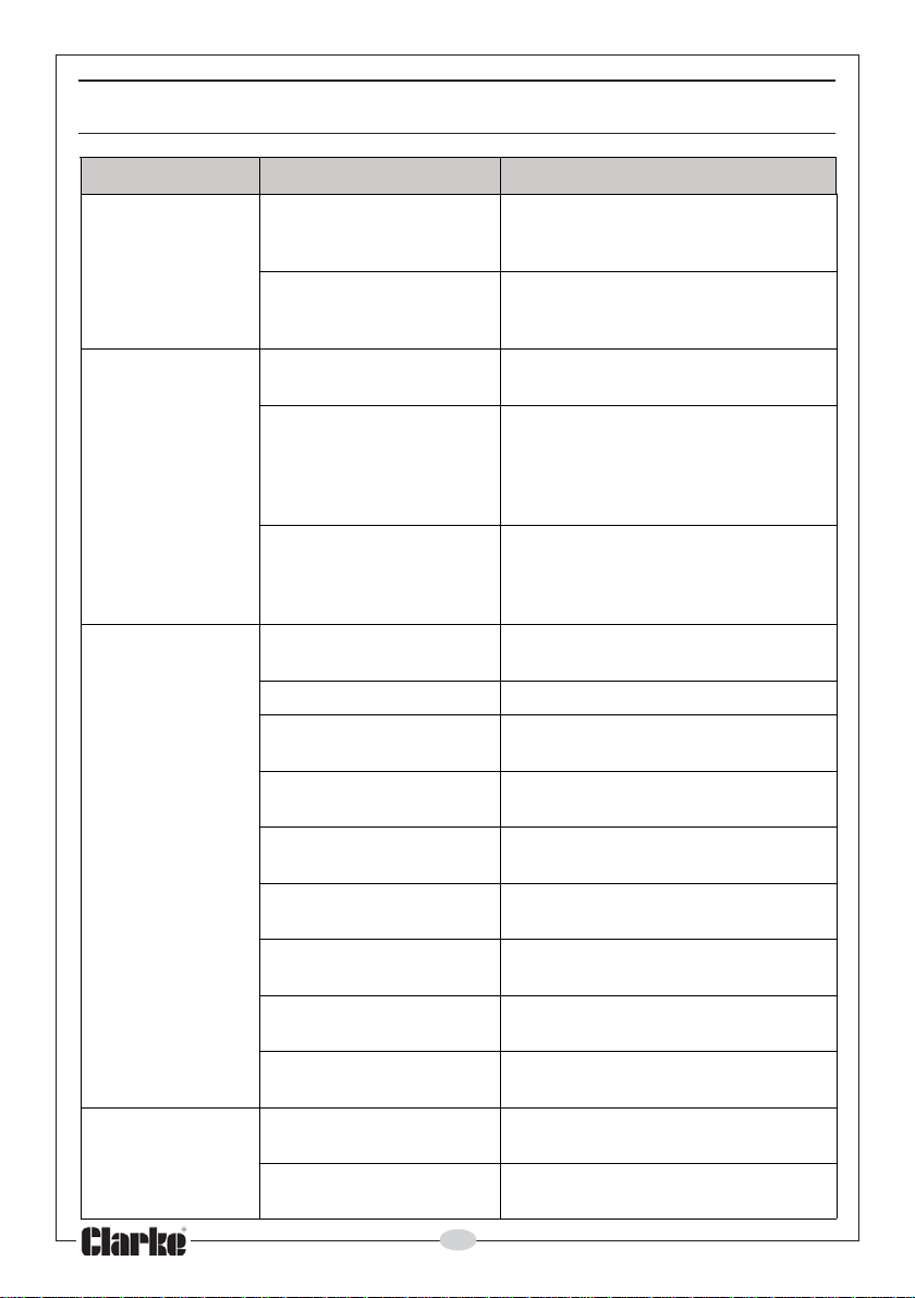
TROUBLESHOOTING
MELBORP ESUAC NOITULOS
.nur
.emirp
.wolf
tonseodpmuP
deziesrellepmIsniammorfpmuptcennocsiD
hcgnimirP
otsliafpmuP
.)teksag
.pmupedisni
tubsnurpmuP
fossolnedduS
am
.tuptuoroopsevig
.enil
.ylppussniamoNdnaylppusrewopdesufkcehC
tonrebma
.yltcerrocdellif
gamad(stniojesoh
de
,pmalcnekorb,esoh
gnittif-lli/degamad
.esohtelnidekcolBtonsitierusne&evlavtoofnaelC
.egakaelenilepiptelnIrofrotcennocdnaepiptelnikcehC
.dekcolbsiretliftelnI.evlavtoofehtnaelcdnakcehC
lacinahcem/rellepmI
.nrowyldabsilaes
lairetamdetsegnoC
dnadegamadrellepmI
.laesroopgnik
.hgihoottfilnoitcuSehtotelbissopsaesolcsapmupteS
yreviledronoitcuS
.detcurtsboenilepip
cusehtninoitsegnoC
hguorhtskaelriA
.laesdegamad
gnikaelroesooL
hgihootsidaehnoitcuS
noitativacgnisuacdna
12
.)gnitaresuf
.dekcolb/
.egakcolb
noitcushguorhtskaelriA
E
noit
.epiptelniotnoitcennoc
.
.yrassecen
.esoh
skael
.riaper
.riaper
neR
ruoyotnruteR
htfolevel
.sevlavrosnoitcirtser
.laeswe
.pmupehtfonoitsop
kcehc(yrassecenfiesufecalper
raelcdnaesuacetagitsevnI.ylppus
riaongnivaelrebmahcgnimirplliF
.9egapnodebircsedsapag
saesohecalper/snoitcennocriapeR
.ctetnemides/dumnidegrembus
telniehtnisknikoneraerehterusn
.deriuqersanethgiT.
rofrelaedEKRALC
.tuonaelc&pmupeltnamsiD
rofrelaedEKRALCruoyotnruteR
.depmupebotdiuqile
erusnednanoitcurtsboevomeR
.enilepipnisknikoneraereht
,sevrucyrassecennudiovA
.tcerrocdnaenilepipkcehC
ehtrewoldnadaehnoitcuskcehC
Page 13
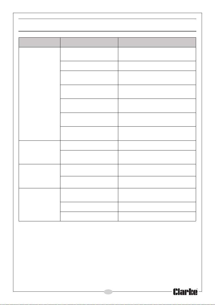
TROUBLESHOOTING
MELBORP ESUAC NOITULOS
hgihootsidaehnoitcuS
.noitativacgnisuacsidna
.retawfowolfevissecxE.retawfowolfesaerceD
ybdesuac.noitcurtsbo
.esion
ronoitarbiveudnU
bats
nosehctiwspmuP
.yldiparffodna
nosehctiwspmuP
onnehwffo&
gniebsiretaw
nward
tonseodpmuP
.ffohctiws
gnitatoresooL
.tnenopmoc
.el
.enilepip
ellepmidegamaDrofrelaedEKRALCruoyotnruteR
.erusserpriawoL.erusserpkce
uonikaeL.yfitcerdnaetagitsevnI
russerProfrelaedEKRALCruoyotnruteR
enilepiptelniniecnatsiseR
tonsipmupfonoitallatsnI
ropmupnitekcopriA
.r
.degamadenarbmeMrofrelaedEKRALCruoyotnruteR
.edistupt
.ytluafevlavnruter-noN.yfitcerdnakcehC
.ytluafhctiwse
onoitsop
.yrassecen
.riaper
hC
.riaper
.riaper
.pmupehtf
cdnaepipkcehC
.riaesaelerotgnisuoh
ehtrewoldnadaehnoitcuskcehC
satuonael
.sriaperrofrelaedruoyotnruteR
.noitisop-erdnapmuppotS
rellepminigulpniardesaeleR
.telnipmuptaretawoN.egakcolbrofkcehC
.rellepmiytluaF.etagitsevni
13
dnaeltnamsiD
Page 14

TECHNICAL SPECIFICATION
006TPB SS0021TPB
thgieWgk2.21gk52.21
mm)HxWxL(snoisnemiD005x072x534794x072x554
yrevileDdetaRxaMnim/ertiL05nim/ertiL16
daeHxaMm53m64
noitacifissalCretaWretaWnaelCdloCretaWnaelCdloC
daerhTteltuO/telnIPSB"1PSB"1
leveLerusserPdnuoSAp
leveLrewoPdnuoSAwLBd08AwLBd38
rewoPdnuoSdeetnarauGAwLBd38<AwLBd68<
yticapaCknaTertiL91ertiL91
eruss
erPdetaRknaTraB3raB3
erutarepmeTgnitarepOC°53xamC°53xam
ylppuSrewoPgnitarepOzH05@V032zH05@V032
Please note that the details and specifications contained herein, are correct at the
time of going to print. However, CLARKE International reserve the right to change
specifications at any time without prior notice.
LBd37ApLBd37
ACCESSORIES
A wide range of airline accessories is available, including Filters, Foot Valves,
Hoses, Couplings, etc. Contact your Clarke dealer for further information or
Clarke International Sales Department on 01992 565333.
The use of parts other than genuine Clarke replacement parts may result in
possible safety hazards or decreased machine performance, and will
invalidate your warranty.
IMPORTANT: The use of parts other than genuine CLARKE replacement parts
may result in safety hazards, decreased performance, and will invalidate
your warranty.
14
Page 15
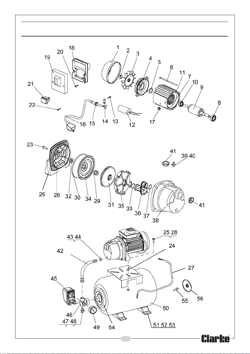
PARTS DIAGRAM-BPT600
15
Page 16
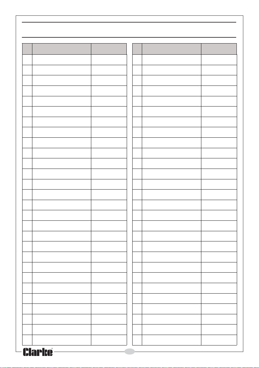
PARTS LIST- BPT600
oN noitpircseD oNtraP oN noitpircseD oNtraP
1revoCnaF10006TPBHD92laeSlacinahceM92006TPBHD
2reniateR20006TPBHD03aid041gniR-O03006TPBHD
3naFgnilooC30006TPB
4gnitsaCdnErotoM40006TPBHD23gniRdexiF23006TPBHD
5rehsaWevaW50006TPBHD33gniR-O33006TPBHD
6mm021t
7rotatSrotoM70006TPBHD53resuffiD53006TPBHD
8Z2-2026gniraeBrotoM8000
9rotoRrotoM90006TPBHD73aid03gniR-O73006TPBHD
01Z2-1026gniraeBrotoM01006TPBHD83gnis
11gnitsaCrotoM11006TPBHD93mm51gulPdedaerhT93006TPBHD
21Fu21roticapaC21006TPBHD04aid81gniR-O04006T
31wercS31006TPBHD14paCtsuDcitsalP14006TPBHD
41pilCelbaC41006TPBHD24esoHdediarB24006TPBHD
51dnalGelbaC51006TPBHD3
61gulP&elbaCrewoP61006TPBHD44hsuBgnilaeSelddiM44006TPBHD
71timmorG71006TPBHD54hctiwSerusserP.hce
81xoBnoitcnuJhctiwS81006TPBHD64rotcennoCyaW-564006TPBHD
91revoCxoBnoitcnuJ91006TPBHD74gulPniarD74006TP
02wercSenihcaM02006TPBHD84gniR-O84006TPBHD
12hctiwSfoorpretaW12006TPBHD94eguaGerusserP94006TPBHD
-fleS22006TPBHD05knaTerusserP05006TPBHD
22wercSgnippat
32tloBdedaeHnellA32006TPBHD15tooFcitsalP15006TPBHD
42esaBcitsalP42006TPBHD2
528MtloBderedluohS52006TPBHD35rehsaW35006TPBHD
62gnitsaCemarF62006TPBHD45egnalFgnitcennoC45006TPBH
72elbaCgnitcennoC72006TPBHD55evlaVtelnIriA55006TPBHD
828MtuN82006TPBHD65revoCevitcetorP65006TPBHD
loBeiTrotoM60006TPBHD43etalPresuffiD43006TPBHD
HD13rellepmI13006TPBHD
6TPBHD63woblEegrahcsiD63006TPBHD
uoHdnE83006TPBHD
4gniR-O34006TPBHD
M54006TPBHD
BHD
58MtuN25006TPBHD
D
PBHD
16
Page 17
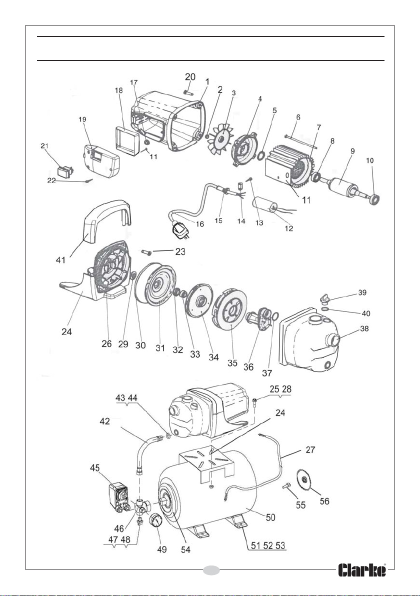
PARTS DIAGRAM-BPT1200SS
17
Page 18
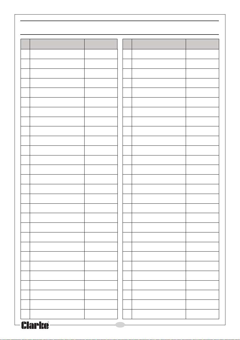
PARTS LIST- BPT1200SS
oN noitpircseD oNtraP oN noitpircseD oNtraP
1revoCrotoM100021TPBHD92laeSlacinahceM920021TPBHD
2reniateR200021TPBHD03aid041gniR-O030021TPBHD
3naFgnilooC300021TPBHD13etalPresuffiD130021TPBHD
4gnitsaCdnErotoM400021TPBHD23gniRdexiF230021TPBHD
5rehsaWevaW500021TPBHD33gniR-
6mm021tloBeiTrotoM600021TPBHD43rellepmI430021TPBHD
7rotatSrotoM700021TPBHD53resuffiD530021TPBHD
8Z2-202
9rotoRrotoM900021TPBHD73aid03gniR-O730021TPBHD
01Z2-1026gniraeBrotoM010021TPBHD83gnisuoHdnE830021TPBHD
11gnitsaCrotoM110021TPBHD93mm51gulPdedaerhT930021TPBHD
21Fu02roticapaC210021TPBHD04gniR-O040021TPBHD
31wercSgnippat-fleS310021TPBHD14dooHcitsalP140021TPBHD
41pilCelbaC410021TPBHD24esoHdediarB240021TPBHD
51dnalGelbaC510021TPBHD34gniR-O340021TPBHD
61gulP&elbaCrewoP610021TPBHD44hsuBgnilaeSelddiM440021TPBHD
71timmorG710021TPBHD54hctiwSerusserP.hceM540021TPBHD
81xoBnoitcnuJraelC810021TPBHD64rotcennoCyaW-5640021TPBHD
91revoCxoBnoitcnuJ910021TPBHD74gulPniarD740021TPBHD
02mm01tloB020021TPBHD84gniR-O840021TPBHD
12hctiwSfoorpretaW120021TPBHD94eguaGerusserP940021TPBHD
22wercSgnippat-fleS220021TPBHD05knaTerusserP050021TPBHD
32mm02tloB320021TPBHD15tooFcitsalP150021TPBHD
42esaBcitsalP420021TPBHD258MtuN250021TPBHD
528MtloBderedluohS520021TPBHD35rehsaW350021TPBHD
62g
72elbaCgnitcennoC720021TPBHD55evlaVtelnIriA550021TPBHD
828MtuN820021TPBHD65revoCevitcetorP650021TPBHD
6gniraeBrotoM800021TPBHD63woblEegrahcsiD630021TPBHD
nitsaCemarF620021TPBHD45egnalFgnitcennoC450021TPBHD
O330021TPBHD
18
Page 19
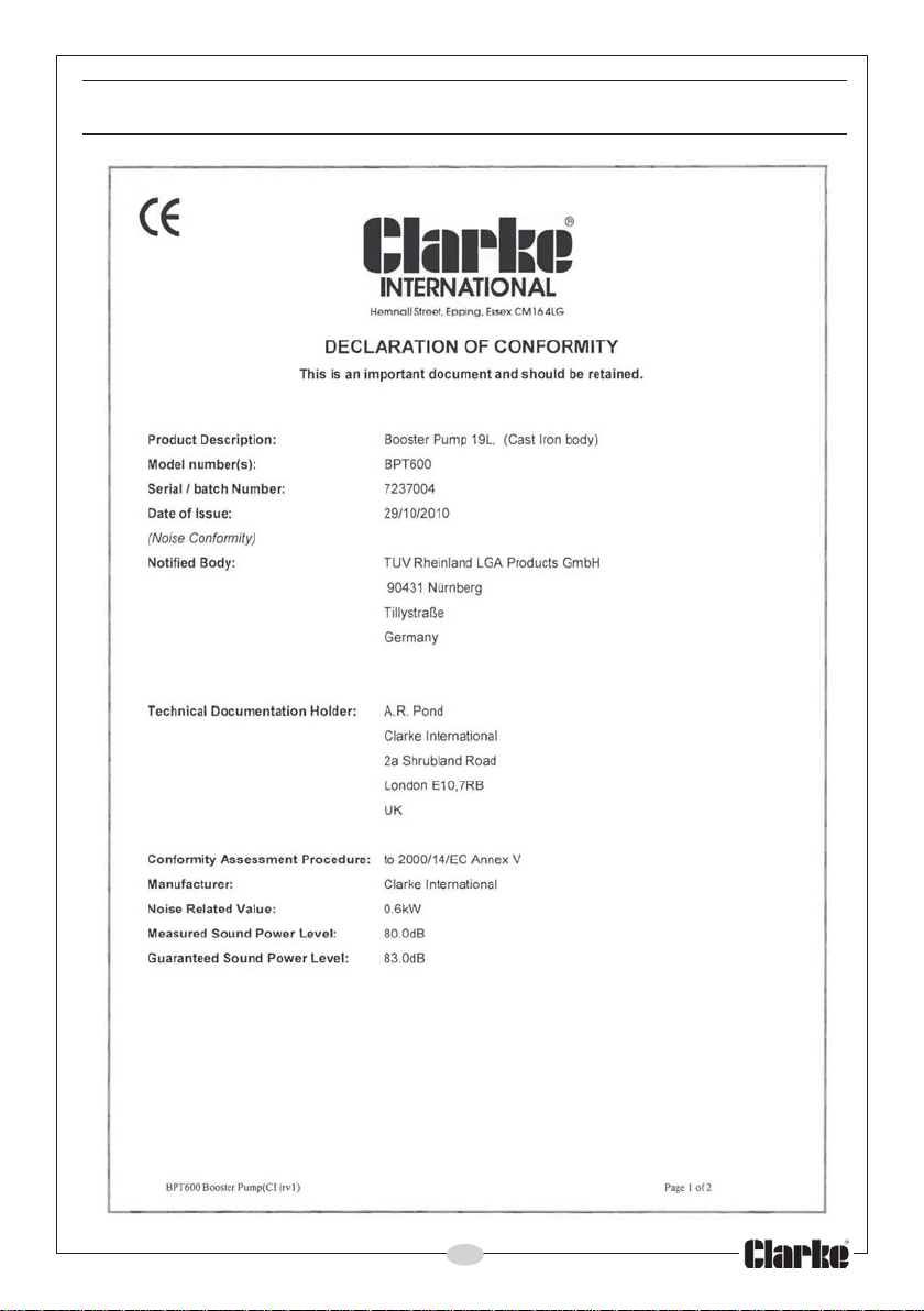
DECLARATION OF CONFORMITY
19
Page 20
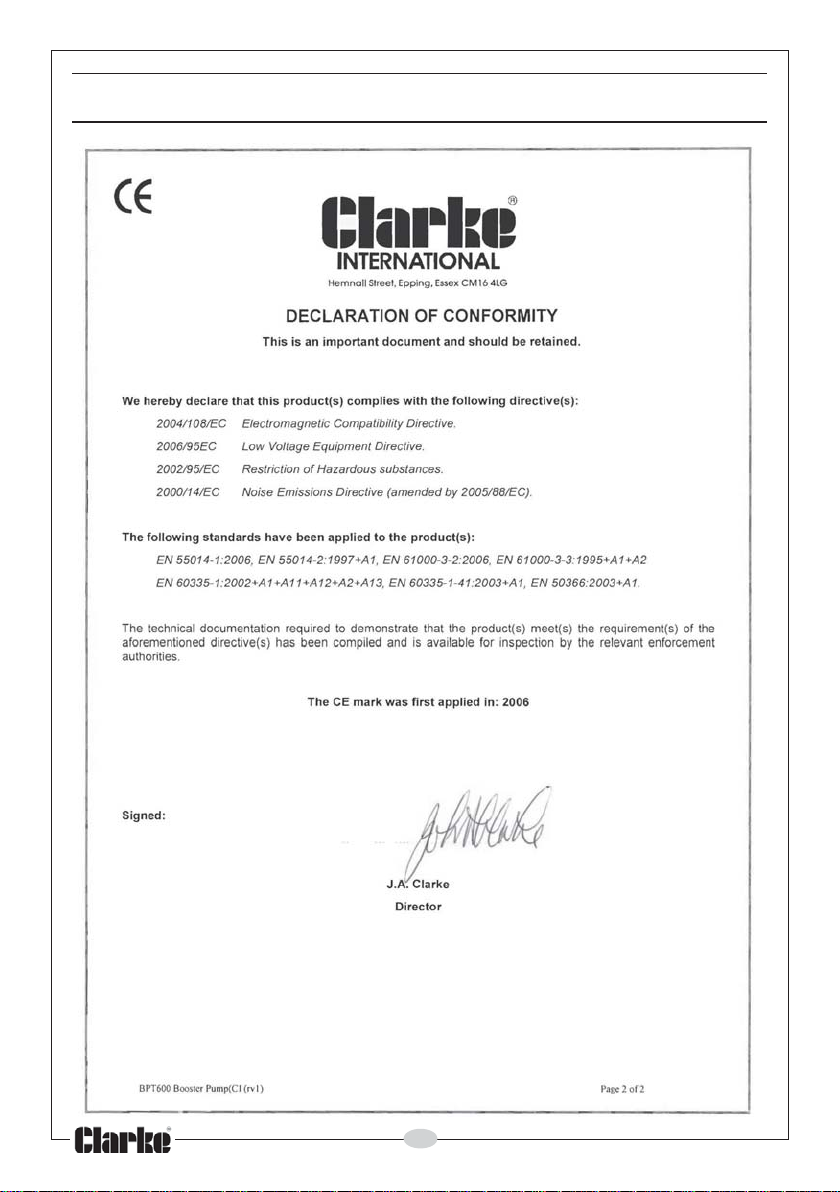
DECLARATION OF CONFORMITY
20
Page 21
DECLARATION OF CONFORMITY
21
Page 22
DECLARATION OF CONFORMITY
22
Page 23

NOTES
_________________________________________________________________________
_________________________________________________________________________
_________________________________________________________________________
_________________________________________________________________________
_________________________________________________________________________
_________________________________________________________________________
_________________________________________________________________________
_________________________________________________________________________
_________________________________________________________________________
_________________________________________________________________________
_________________________________________________________________________
_________________________________________________________________________
_________________________________________________________________________
_________________________________________________________________________
23
Page 24

 Loading...