

Page 1
OPERATING & MAINTENANCE
INSTRUCTIONS
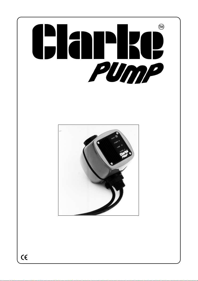
ELECTRONIC CONTROL UNIT
7/97
Model No. EPC1000
Part No. 7230700
Page 2

GUARANTEE
This product is guaranteed against faults in
manufacture for 12 months from purchase date .
Keep your receipt as proof of purchase.This
guarantee is invalid if the product has been
abused or tampered with in any way, or not used
for the purpose for which it is intended. The
reason for return must be clearly stated. This
guarantee does not affect your statutory rights.
Please note that dismantling this product will
invalidate the guarantee
APPLICATIONS
This computerised electronic unit can be used
to convert pumps into automatic booster sets.
The device provides 3 main functions:
● It provides automatic operation of your
pump.
The unit will automatically switch the pump ON
when the water pressure drops to about 1.5 bar,
and switches the pump OFF when it reaches
its’ maxim um value. In pr actice, this means that
it switches the pump ON and OFF whenever
the tap or lance etc., is opened.
● It protects the pump from running dry.
The unit has an integrated dry running safety
circuit, which switches the pump OFF when
there is no water flow. This will result in the red
LED beiing displayed. (To restart the unit, the
reset button must be pressed.)
● It automatically sets the cut-out
pressure. (This is normally the max.
pump pressure).
The cut-in pressure is preset during manufacture
to 1.5 bar - no manual adjustment should be
necessary.
IMPORTANT:
This device must not be installed more
than 14 metres below the delivery outlet.
SAFETY PRECAUTIONS
1. DO NOT attempt to modify or alter the
pump in any way.
2. Observe all electrical precautions. DO NOT
allow the unit to be submerged.
Ensure it is protected from the elements
at all times.
3. Read and comply with all precautions
specified in your pump manual.
4. If your pump is used f or draining ponds or
swimming pools, ensure that before
operation all pond life is removed, and duriing
operation no person or animal is allowed in or
near the pool.
ELECTRICAL INSTALLATION
Connect the mains lead to a standard 230Volt
(50Hz) electrical supply through an approved
plug or a suitably fused isolator switch. We
recommend that these pumps be fitted with a
Residual Current Device (RCD).
WARNING:
THIS APPLIANCE MUST BE EARTHED
If the device is to be connected to an outdoor
electrical supply, make sure that both the plug
and the socket are of a BS approved waterproof
design.
In the event that the device is directly wired into
the electrical system, it must be carried out in
accordance with IEE regulations.
If used for draining swimming pools or ponds,
the device MUST be fitted with a Residual
Current Device (RCD), with a rated residual
operating current of no greater than 30mA.
IMPORTANT: The wires in the mains lead are
coloured in accordance with the following code:
Green & Yellow - Earth
Blue - Neutral
Brown - Live
As the colours of the flexible cord of this
appliance may not correspond with the coloured
markings identifying terminals in your plug
proceed as follows:
Connect GREEN & YELLOW cord to plug
terminal marked with a letter “E” or Earth symbol
“ “ or coloured GREEN or GREEN & YELLOW .
Connect BROWN cord to plug terminal marked
with a letter “L” or coloured RED
Connect BLUE cord to plug terminal marked
with a letter “N” or coloured BLACK
FUSE RATING
The fuse in the plug for this appliance must be
rated at 13 amps.
If this appliance is fitted with a plug which is
moulded onto the electric cable (i.e. nonrewirable) please note:
Page 3
1. The plug must be thrown away if it is cut
from the electric cable. There is a danger
of electric shock if it is subsequently
inserted into a socket outlet.
2. Never use the plug without
the fuse cover fitted.
3. Should you wish to replace
a detachable fuse carrier,
ensure that the correct
replacement is used (as
indicated by marking or
colour code).
4. Replacement fuse covers
can be obtained from your
local dealer or most
electrical outlets
5. The fuse in the plug must be
replaced with one of the
same rating (13 amps) and
this replacement must be
ASTA approved to BS1362.
IMPORTANT:
If you are in any doubt regarding electrical
you should consult a qualified electrician.
EXTENSION CABLES.
The maximum length of cable should not
exceed 25 metres, and the size of the
conductors must be AT LEAST the same size
as that of the unit.
Ensure that all connections are well clear of
the water.
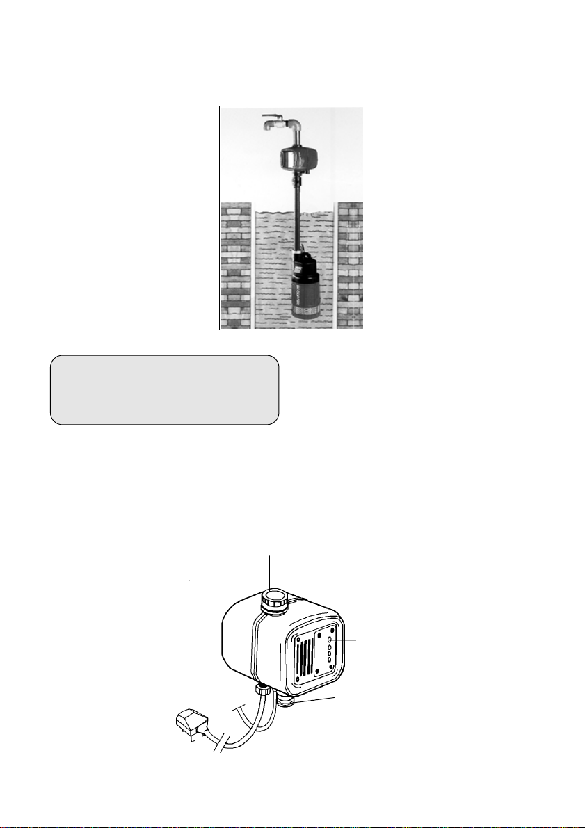
PUMP to EPC 1000 CONNECTION
The unit is provided with two cables, one
of which is fitted with a standard 13
amp plug and when connected to
the mains supply, carries the
supply to both the Electronic
Control Unit and the pump.
The other cable (4) should be
fitted with a trailing socket so that
the 13amp plug from the pump
may be plugged into it.
IMPORTANT:
If the device is to be
connected to an outdoor
electrical supply, make sure that both the plug
installation,
2
4
and the socket are of a BS approved waterproof
design and are protected from the elements..
INSTALLATION
Screw the 1 BSP inlet, male
thread (1) on to the female thread
of the pumps delivery outlet.
Screw the delivery pipe
connector to the units delivery
outlet (2)
Plug in the power cable.
NOTE It is strongly advised that
a filter be connected to the
pumps water inlet to protect both
the pump AND the EPC1000.
Ensure that the vertical distance
from the outlet of the unit to the
highest point of discharge, is
NOT GREATER THAN 14
metres (44ft).
If necessary, locate the unit so that it is not more
than 14 metres below the point of discharge.
OPERATION
Ensure the pump is fully primed BEFORE
switching ON. See your pumps Instruction
Manual for details.
Additionally, you should always fit a non-return
valve to the suction line. (A Foot valve and Filter
is available from your CLARKE dealer).
Shut OFF all devices on the pressure side of
the pump - taps, lance etc., and ensuring all
precautions have been observed, switch on the
pump at the electrical mains supply.
If the pump does not deliver water within 40
seconds or so, the dry running safety device
will operate, and the pump will stop.
To restart, press the RESET button (3).
It is possible to carry out this
procedure for 5 operations,
3
after which time, the RED LED
will blink, and the reset button
will no longer operate. It will be
necesary to investigate and rectify
the cause of the problem. Switch OFF
1
switching back ON, press the reset button once
more.
If your pump still does not operate after several
such operations, consult your CLARKE dealer.
the pump in order to do so. When
Page 4
NOTE:
The most common problem associated with
water pump operation, is leaks on the
SUCTION side of the pump. Even a pin hole
in the inlet hose is sufficient to seriously
reduce or stop altogether, the drawing of
water. Ensure all connections are air tight
and the inlet hose is completely sound.
LED DISPLAY
The unit is equipped with
three LEDs which provide
information as to the
pumps status.
GREEN LED indicates that
the pump is correctly
connected to the mains
supply, and is ready for
use.
YELLOW LED indicates
that the pump is operating
normally.
RED LED indicates that a
problem exists and the
pump is not functioning due
to the following:
Dry running safety device has intervened.
Pump impeller jammed no water flow.
Pumps overload protector has tripped.
Leaks on suction side of pump.
To cancel the red LED, and reset the pump,
press the reset button.
TROUBLE SHOOTING
Pump constantly switches ON and OFF.
This is caused if there are leaks of any kind on
the OUTLET side of the pump. Even a small
leak will be sufficient to keep the pump running
constantly. Ensure ALL connections are water
tight, and that taps etc., do not drip.
It is also possible that
foreign matter has found its
way into the pump. In which
case, disconnect the pump,
and rinse it thoroughly using
a water jet, and clean water.
The pump does not work.
Calcium build up inside
device.
Unplug and disconnect the
pump from the water and
electrical supplys. Fill with
anti-liming agent or a
mixture of water and
vinegar, and leave to soak.
Rinse through thoroughly before re-connecting.
For other possible problems, consult the pumps
Instruction Manual.
SPECIFICATIONS
Power Source .................................................... 230V 50Hz
Operating Range ............................................... 1.5bar - Max. Pump Pressure
Max. Delivery .................................................... 120 l/min (32 gal/min)
Max. Water Temp. ............................................ 35°C
Max Operating Press ........................................ 8 bar
Degree of Protection ......................................... IP44
For Spare Parts and Servicing, please contact your nearest dealer, or
CLARKE International, on one of the following numbers.
PAR TS - 0181 558 6696 SERVICE - 0181 556 4443
Please note that the details and specifications contained herein, are correct at the time of going to print. However, CLARKE
PARTS & SERVICE FAX - 0181 558 3622
International reserve the right to change specifications at any time without prior notice.
 Loading...