

Page 1
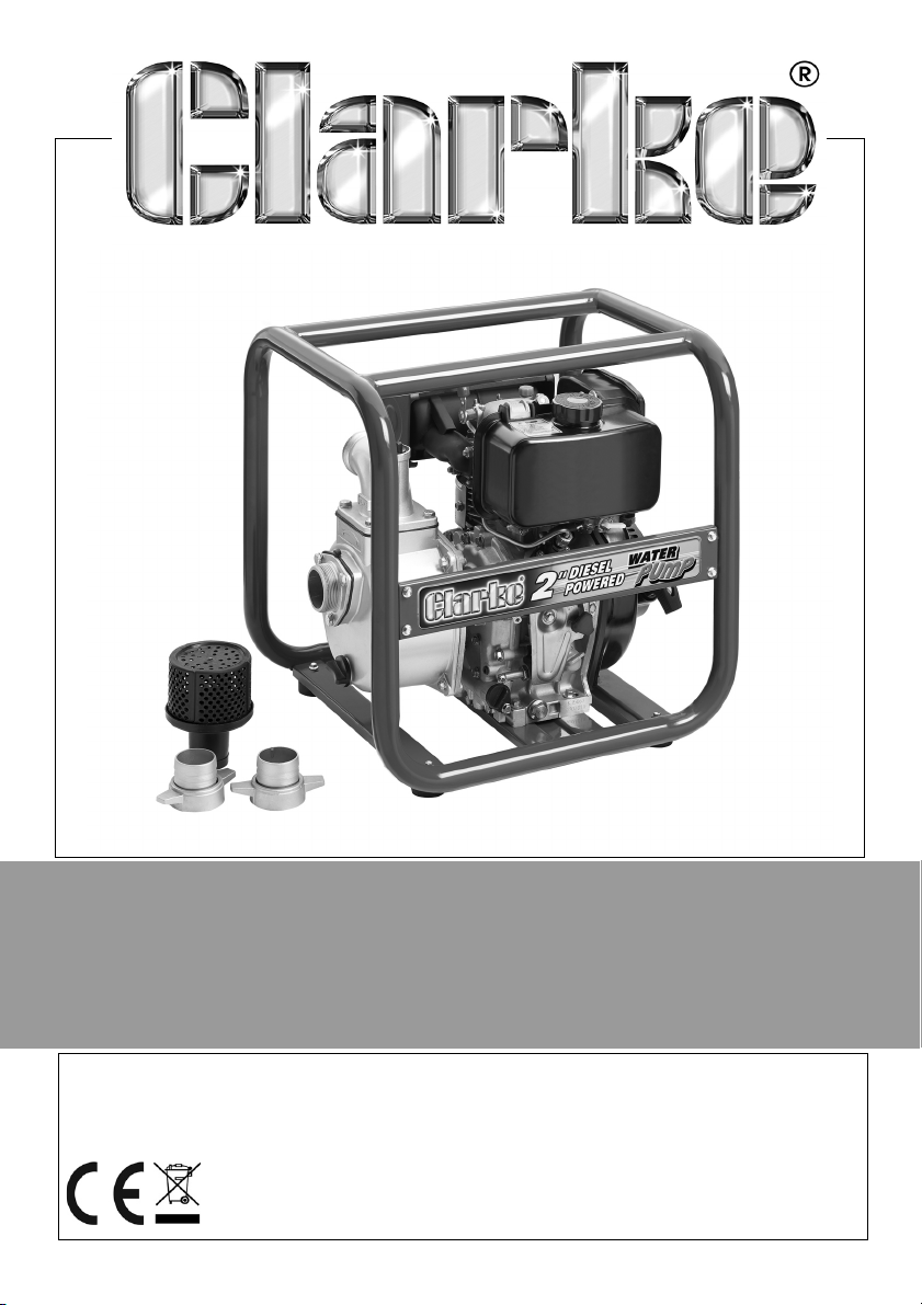
ENGINE DRIVEN 2” DIESEL PUMP
MODEL NO: DW50
PART NO: 7230170
OPERATION & MAINTENANCE
INSTRUCTIONS
ORIGINAL INSTRUCTIONS
LS0518 ISS 2
Page 2
INTRODUCTION
Thank you for choosing this Clarke Pump.
The function of this pump is to move clean /dirty water (with solids in
suspension upto 10-12 mm in diameter).
DO NOT use it to pump:
•Sewage
• Dangerous liquids.
• Salt water
Before you use this pump read the manual fully.
GUARANTEE
This pump is guaranteed against faulty manufacture for a period of 12 months
from the date of purchase.
Please keep your receipt which will be required as proof of purchase.
This guarantee is invalid if the pump has been abused, tampered with, or not
used for its primary function.
Faulty goods must be returned to their place of purchase, no pump can be
returned to us without prior permission.
This guarantee does not effect your statutory rights.
INVENTORY
You should find the items in the list below in the carton.
1 x Diesel Powered Water Pump 2 x Rubber Sealing Rings
2 x 2" Hose adaptors 2 x 2" Hose clips
1 x Inlet Strainer (in two pieces) with 2" Hose
Coupling/clip
Speak to your Clarke dealer if items are missing or damaged.
2
Parts & Service: 020 8988 7400 / E-mail: [email protected] or [email protected]
Page 3
GENERAL SAFETY RULES
WARNING: WHEN USING PUMPS, ALWAYS FOLLOW BASIC SAFETY
PRECAUTIONS TO REDUCE THE RISK OF FIRE, ELECTRIC SHOCK AND
PERSONAL INJURY. READ ALL INSTRUCTIONS BEFORE YOU
OPERATE THIS PUMP AND SAVE THEM FOR FUTURE REFERENCE.
1. ALWAYS obey all safety precautions for the handling of fuel.
2. ALWAYS make sure that you are familiar with this pump, and follow all
instructions in this manual.
3. ALWAYS make sure that the pump is positioned correctly to prevent it from
moving during operation.
4. Keep the area adjacent to the pump clear.
5. ALWAYS connect the strainer to the suction hose to stop stones and other
solids from being pulled into the pump. These can cause damage to the
pump.
6. ALWAYS keep the pump dry and clear of the discharge hose.
7. Only use parts supplied by the manufacturer. Using non-standard parts can
be dangerous.
8. ALWAYS use at least 300mm of flexible hose to make plumbing connections
to the pump. Rigid piping can put stress on the pump, causing damage. If
you use rigid piping, it must be supported to eliminate strain on the
connections.
9. DO NOT refuel the engine while it is operating and let the engine cool
sufficiently before refuelling.
10. DO NOT use to pump petrol (or other flammable liquids), or corrosive
chemicals. The function of this pump is to pump WATER ONLY.
11. DO NOT operate this pump in an explosive atmosphere, near combustible
materials, or where there is insufficient ventilation.
12. DO NOT let children use this pump.
13. DO NOT run the pump dry. Always fill the pump with water before starting.
14. DO NOT direct the discharge flow towards another person.
15. DO NOT over-tighten drain or filler plugs. Excessive force can damage the
threads or the pump body.
16. DO NOT direct the water discharge towards electrical wiring or equipment.
3
Parts & Service: 020 8988 7400 / E-mail: [email protected] or [email protected]
Page 4
GENERAL SAFETY IN THE WORKPLACE
1. Always keep work area clean & tidy. Cluttered work areas invite accidents.
2. Never over-reach. Keep proper footing and balance at all times.
3. Always make sure that the workplace is well lit. Make sure that that lighting
is placed so that you will not be working in your own shadow.
4. Dress correctly. Loose clothing or jewellery can get caught in moving parts.
Non-slip footwear is recommended. Wear protective hair covering to
contain long hair.
5. Always wear safety glasses. (Everyday glasses are not safety glasses).
CARE OF PUMPS
1. Always examine the pump for damage that can effect the operation.
2. The Clarke service department will only replace damaged components
using original spare parts.
Keep the instructions for future reference.
SAFETY SYMBOLS
The meanings of the markings and symbols on the pump are shown below.
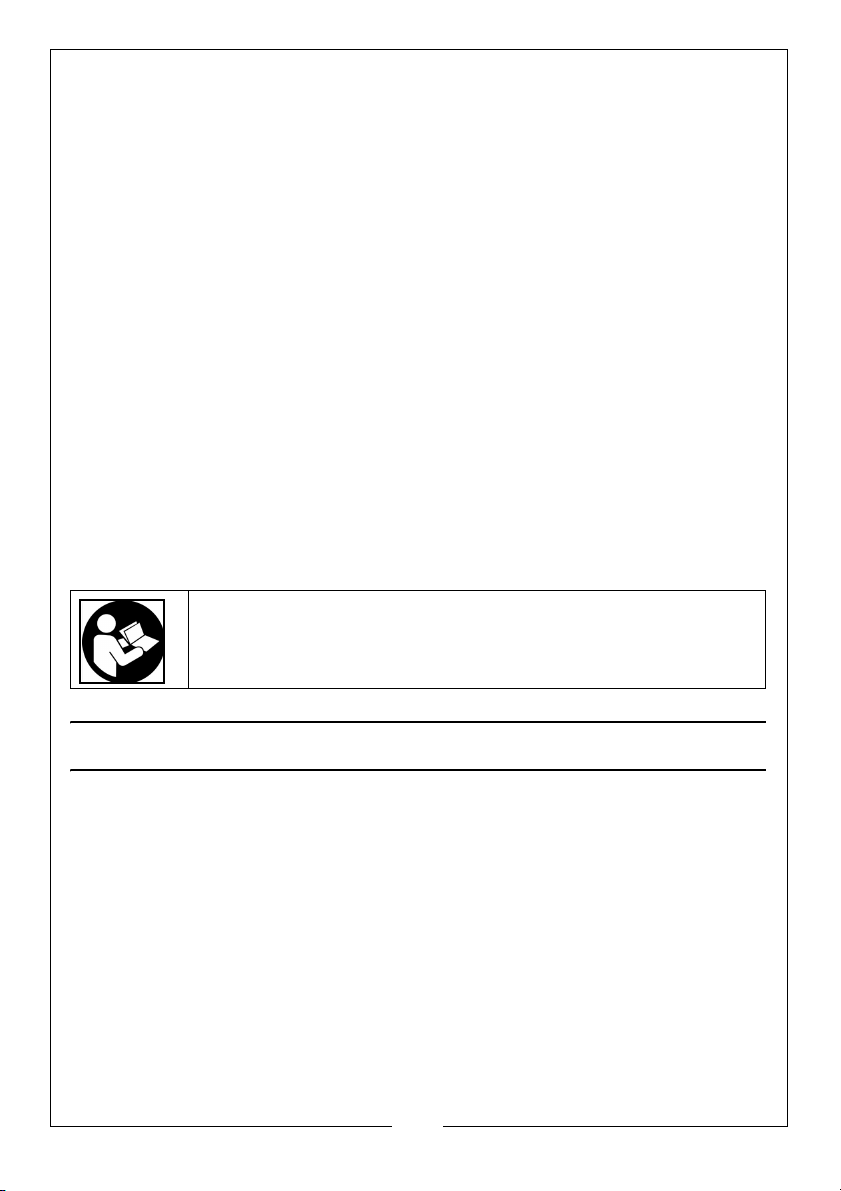
Read this manual before use and keep it for future reference
ENVIRONMENTAL PROTECTION
At the end of its working life, do not discard this pump or its components with
general household waste. Packaging must be taken to a recycling centre and
discarded appropriately.
4
Parts & Service: 020 8988 7400 / E-mail: [email protected] or [email protected]
Page 5
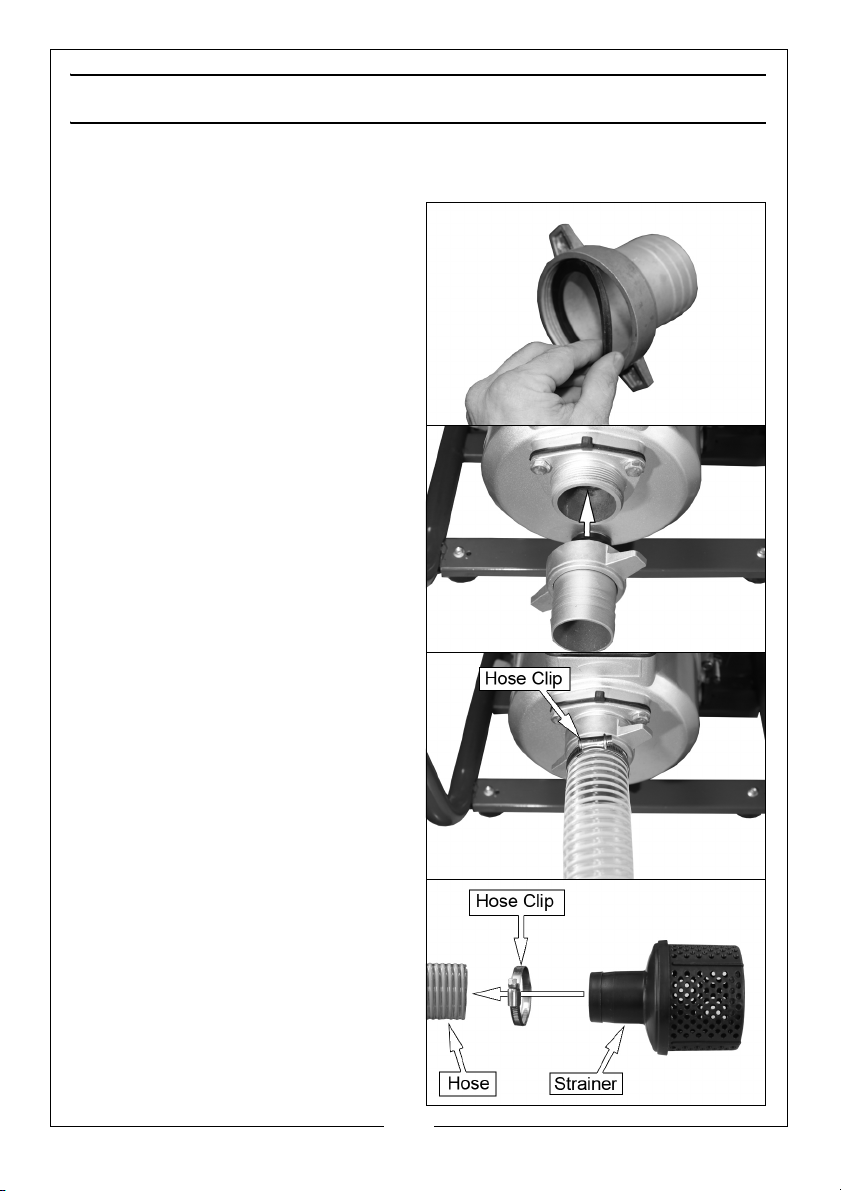
ASSEMBLY
INSTALL THE SUCTION HOSE
1. Put the rubber washer into the
adaptor.
• Make sure that it is seated
correctly.
2. Screw the adaptor onto the
pump.
• PTFE tape can be used to
ensure a good seal.
3. Slide the hose on to the adaptor
and lock in position with the hose
clip supplied.
• 2" Reinforced Hose is available
from your Clarke supplier (Part
number - 7955020)
4. Install the strainer on to the other
end of the hose following the
picture on the right.
5
Parts & Service: 020 8988 7400 / E-mail: [email protected] or [email protected]
Page 6
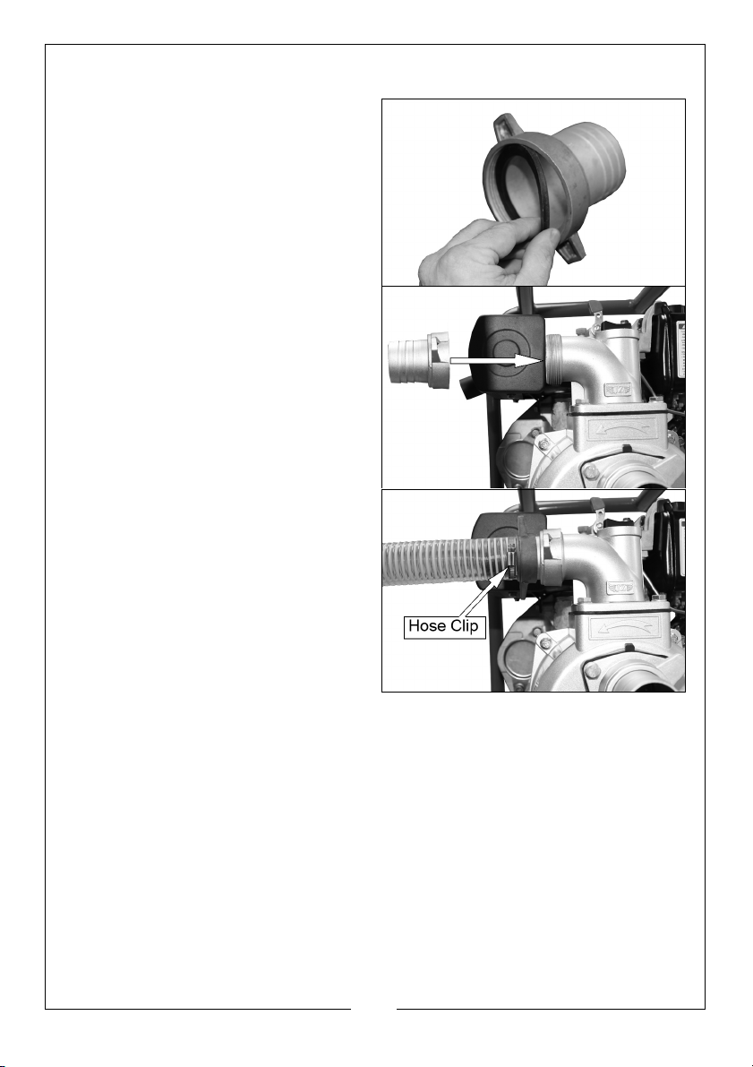
INSTALL THE DISCHARGE HOSE
1. Put the rubber washer into the
adaptor.
• Make sure that it is seated
correctly.
2. Screw the adaptor onto the
pump.
• PTFE tape can be used to
ensure a good seal.
3. Slide the hose on to the adaptor
and lock in position with the hose
clip supplied.
• 2" Reinforced Hose is available
from your Clarke supplier (Part
number - 7955020)
• 2" Lay Flat Hose is available
from your Clarke supplier (Part
number - 7955160)
6
Parts & Service: 020 8988 7400 / E-mail: [email protected] or [email protected]
Page 7
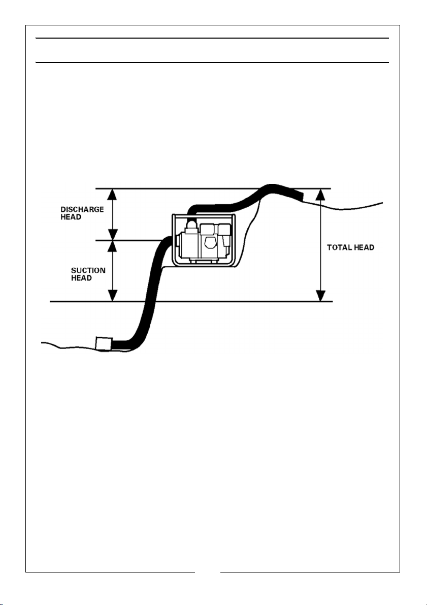
BEFORE USE
POSITIONING THE PUMP
For optimum performance, place the pump near the water level and use
hoses that are no longer than necessary.
As “head” (pumping height) increases, pump output decreases. The length
and size of the suction and discharge hoses can also effect pump output.
The discharge head is always greater than the suction head, so it is important
for the suction head to be the smaller part of the total head.
7
Parts & Service: 020 8988 7400 / E-mail: [email protected] or [email protected]
Page 8
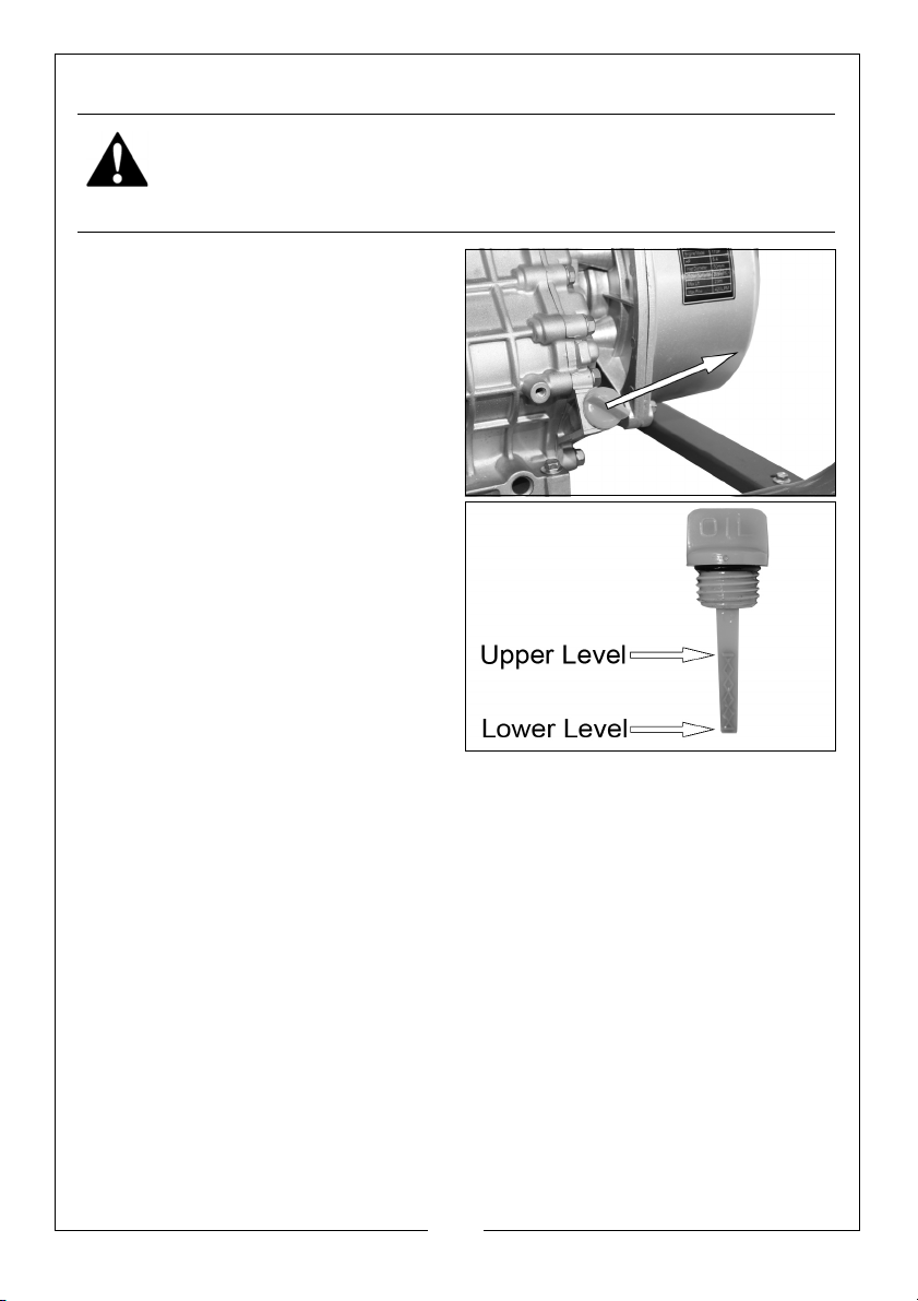
CHECK THE ENGINE OIL LEVEL
WARNING: TO DO THIS CHECK, STAND THE PUMP ON LEVEL GROUND
WITH THE ENGINE SWITCHED OFF.
WARNING: BE CAREFUL NOT TO TOUCH HOT PARTS OF THE PUMP
WHEN CHECKING THE OIL LEVEL.
1. Turn the oil filler cap anticlockwise and remove from the oil
filler tube.
2. Wipe the dipstick clean with a lint
free cloth.
3. Slide the dipstick into the oil filler
tube and remove it again. Do not
screw in the oil filler cap/dipstick
when doing this.
4. If the oil level is at or below the
‘Lower level’ mark on the dipstick,
Fill the crankcase with oil to the
‘Upper level’ mark.
• Oil capacity is 1 Litre.
• We recommend you use
SAE15W40 oil in this pump,
available from your Clarke
dealer.
5. Replace the oil filler cap.
8
Parts & Service: 020 8988 7400 / E-mail: [email protected] or [email protected]
Page 9
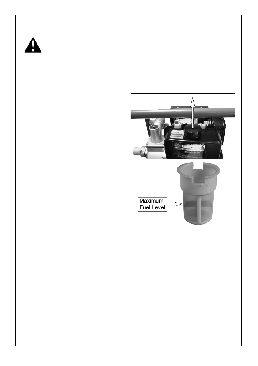
ADD DIESEL FUEL
WARNING: REFUEL IN A VENTILATED AREA, AWAY FROM SOURCES
OF IGNITION.
WARNING: IF THE ENGINE IS HOT, LET IT COOL BEFORE REFUELING.
WARNING: KEEP FUEL OUT OF THE REACH OF CHILDREN.
RECOMMENDED FUEL
Only use regular diesel.
1. Remove the fuel filler cap.
• Inside the fuel tank is a fuel filter
which collects contaminants as
you refuel.
2. Slowly add fuel to the fuel tank.
• Make sure that the fuel level is
not above the maximum fuel
level mark in the fuel filter.
3. Replace the fuel tank cap.
9
Parts & Service: 020 8988 7400 / E-mail: [email protected] or [email protected]
Page 10
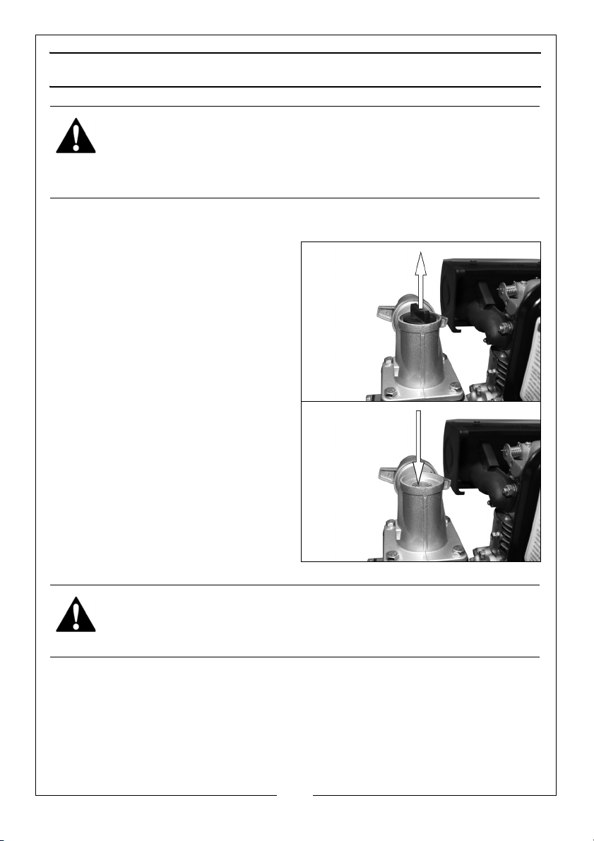
OPERATION
WARNING: WHEN YOU OPERATE THE PUMP, THE EXHAUST MUFFLER
WILL BECOME VERY HOT.
WARNING: DO NOT OPERATE THE ENGINE IN A CLOSED SPACE,
MAKE SURE THAT THERE IS SUFFICIENT AIRFLOW AROUND THE
PUMP.
PRIME THE PUMP
1. The pump MUST be primed before
use.
2. Before starting the engine,
remove the filler cap from the
pump chamber.
3. Fill the pump chamber and inlet
hose with water.
NOTE: A foot valve (not supplied)
connected to the lower end
of the inlet hose between
the hose and the strainer will
help to maintain priming,
4. Replace the filler cap and tighten
it securely.
WARNING: OPERATING THE PUMP DRY WILL DESTROY THE PUMP
SEAL. IF THE PUMP IS OPERATED DRY, STOP THE ENGINE
IMMEDIATELY, AND LET THE PUMP COOL BEFORE PRIMING
10
Parts & Service: 020 8988 7400 / E-mail: [email protected] or [email protected]
Page 11
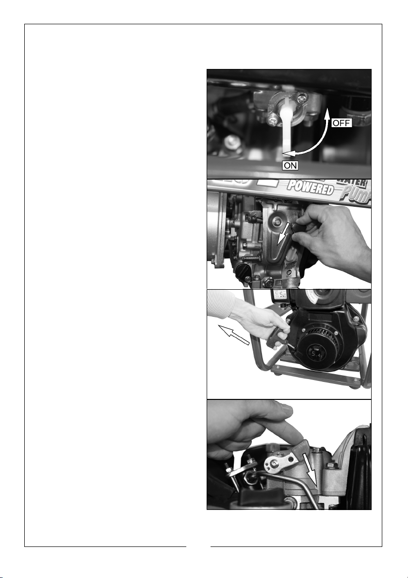
START THE ENGINE
1. MAKE SURE THE PUMP IS PRIMED (SEE PAGE 10)
2. Set the fuel valve to the (O) ON
position.
3. Set the speed adjusting knob to
the START position.
4. Hold the starting handle tightly
and pull until you start to feel
resistance, then return it slowly to
its initial position.
5. Push the decompression lever
down and release.
11
Parts & Service: 020 8988 7400 / E-mail: [email protected] or [email protected]
Page 12

6. Pull the starting handle lightly until
you start to feel resistance. Then
pull up and away suddenly to
start the engine.
NOTE: You may need to use 2
hands to pull the recoil
starter, If so get another
person to hold the pump
steady.
NOTE: If the engine fails to start go
back to step 4 and try again.
WARNING: WHEN THE ENGINE HAS STARTED, RETURN THE
STARTING HANDLE SLOWLY TO PREVENT INJURY/DAMAGE AS IT
RETURNS.
FIRST 20HOURS USE ONLY
Run the engine/pump at mid power
for the first 20 hours.
12
Parts & Service: 020 8988 7400 / E-mail: [email protected] or [email protected]
Page 13
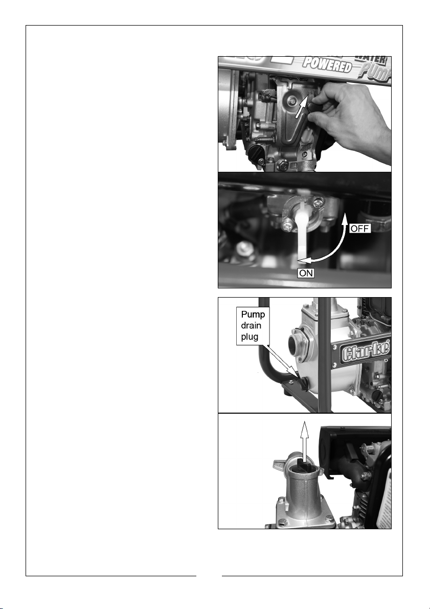
STOPPING THE ENGINE
1. Set the speed adjusting knob to
“Stop” position.
• You do not need to use the
decompression lever when
stopping the engine.
2. Turn fuel switch back to “S” (OFF)
position.
3. Hold the starting handle tightly
and pull until you start to feel
resistance, then return it slowly to
its original position.
NOTE: This can help to prevent
cylinder corrosion.
AFTER USE
1. Remove the pump drain plug to
drain the pump chamber.
2. Remove the filler cap, and flush
the pump chamber with clean,
fresh water.
3. Let the water drain from the pump
chamber, then replace the filler
cap and drain plug.
13
Parts & Service: 020 8988 7400 / E-mail: [email protected] or [email protected]
Page 14
MAINTENANCE
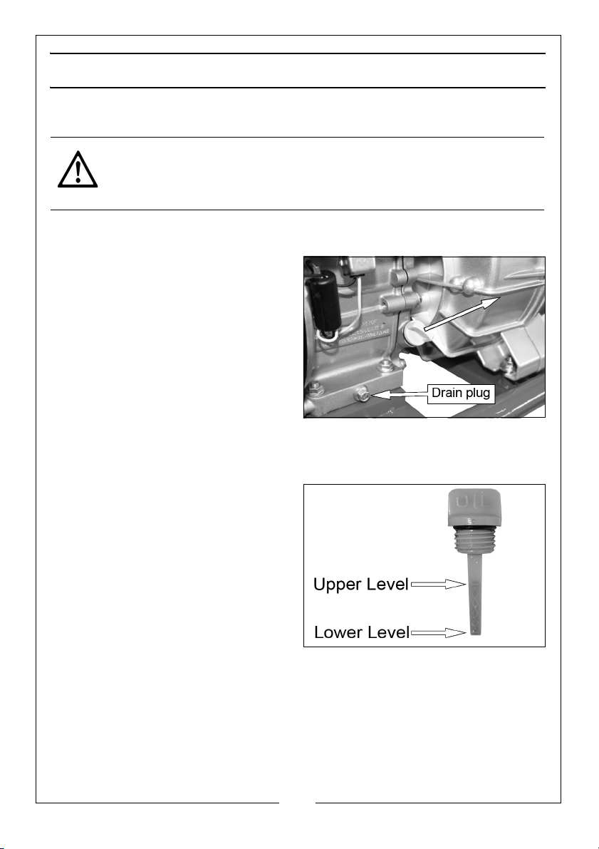
CHANGING THE ENGINE OIL
CAUTION: PROLONGED EXPOSURE TO USED ENGINE OIL IS DANGEROUS,
ALWAYS WASH YOUR HANDS THOROUGHLY AFTER HANDLING USED
ENGINE OIL.
The oil in the engine must be changed after the first 20 hours use and then
every 6 months or 100 running hours.
1. Unscrew and remove the oil filler
cap/dipstick.
2. Put an oil collection tray below
the drain plug.
3. Unscrew the drain plug and let
the used engine oil drain from the
crankcase into the oil collection
tray.
NOTE: Drain the engine oil when the
engine is warm; as the oil will
flow more freely this will make sure that the oil flows out faster.
4. Replace the drain plug.
5. Fill the crankcase with oil to the
‘Upper level’ mark on the dipstick.
6. Replace the oil filler cap/dipstick.
ENVIRONMENTAL PROTECTION
One of the most damaging sources of pollution is oil, do not throw it away or
pour it down drains. Put it in a leak proof container and take it to your local
waste disposal site.
14
Parts & Service: 020 8988 7400 / E-mail: [email protected] or [email protected]
Page 15
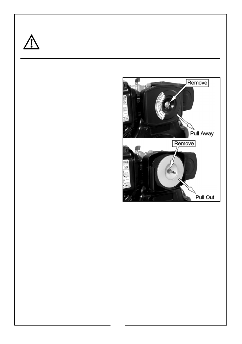
CHANGING THE AIR FILTER
CAUTION: DO NOT OPERATE THE PUMP WITHOUT THE AIR FILTER
INSTALLED AS THIS WILL CAUSE EXCESSIVE WEAR TO THE ENGINE.
Clean the air filter after 50 hours of operation (or more often in unusually dusty
conditions) as follows.
1. Remove the wingnut and lift off
the air filter cover.
2. Remove the nut that holds the air
filter in position.
3. Remove the air filter element.
4. Clean the air filters or replace if
necessary.
• If the filter is dirty, wash the filter
in a solution of warm water and
mild detergent and rinse
thoroughly. Let the filter dry
fully.
• When it is dry, dip the filter in clean engine oil and squeeze out
excess oil.
• It is normal for blue smoke to come out of the exhaust for a short
time when the filter has been cleaned.
5. Replace the filter and cover.
STORAGE
Before long-term storage:
1. The pump must be cleaned by flushing with clean water, otherwise, the
impeller may be damaged in next operation. After flushing, remove the
drain plug and drain all the water from the pump. Then replace the drain
plug.
2. Discharge the fuel in the fuel tank. Remove the fuel pipe connector to
drain the fuel, then retighten the fuel pipe connector.
15
Parts & Service: 020 8988 7400 / E-mail: [email protected] or [email protected]
Page 16
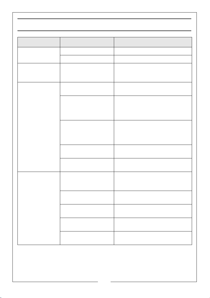
TROUBLESHOOTING
PROBLEM CAUSE SOLUTION
The engine does
not start.
The engine stops
and will not
restart.
The pump fails to
prime.
Low output from
pump.
No fuel in tank. Add fuel.
Fuel valve is set to OFF, Set the fuel valve to ON,
No fuel in tank. Add fuel to the tank.
Priming chamber not
filled correctly.
Air leaking due to
damaged hose,
broken hose clamps,
split/ill-fitting gasket.
Blocked inlet hose. Clean strainer and make sure that
Damaged impeller. Disassemble the pump and
Air leaking through
damaged seal.
The impellor is
clogged.
Pickup or delivery hose
obstructed.
Suction lift too high. Set the pump nearer to the water
Congested material
inside pump.
Damaged impeller. Disassemble the pump and
Fill priming chamber leaving no
air gap.
Repair as necessary.
it is not submerged in mud or
sediment. Make sure that there
are no kinks in the delivery hose.
replace the impeller.
Replace seal.
Clean strainer and make sure that
it is not submerged in mud or
sediment.
Clear obstruction and make sure
that there are no kinks in hose.
level.
Disassemble the pump and clean
out.
replace the impeller.
If you cannot correct the fault, speak to your local dealer or the Clarke
International service department.
16
Parts & Service: 020 8988 7400 / E-mail: [email protected] or [email protected]
Page 17
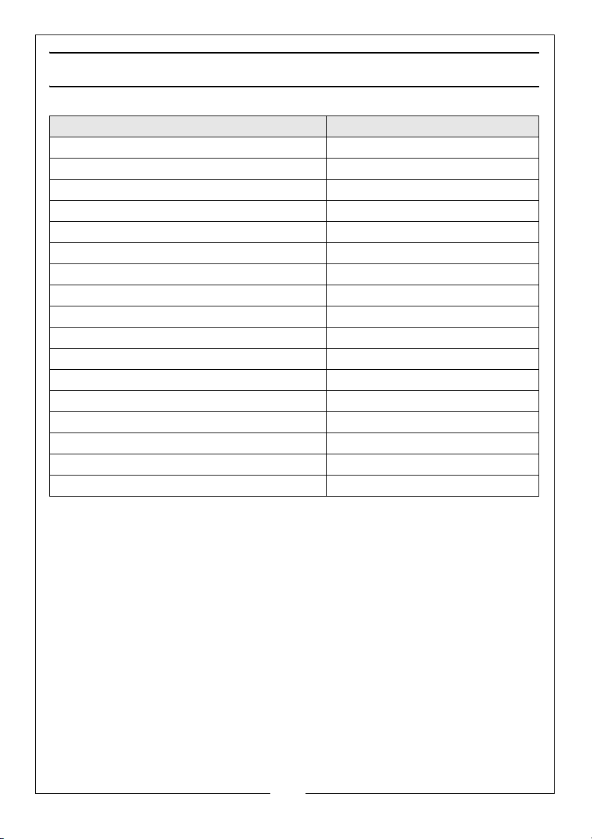
SPECIFICATION
Item Spec
Pump dimensions (L x W x H) 501 x 423 x 520 mm
Pump Weight (kgs) 43.68 kg
Water classification Dirty / Clean (NOT SEWAGE)
Max solids in suspension 10-12 mm
Inlet/Outlet Size 2” BSP
Maximum Flow 450lL/min max
Max Head 27 m
Suction Head 7 m
Max Pressure 2.3 bar
Run time @75% rated load 4 hrs
Engine type/speed 5.4 HP @ 3600 rpm
Fuel tank capacity 2.5 L
Lubrication oil capacity/grade 1Litre (SAE 15W40)
Sound Pressure Level 90.69 dB LpA
Sound Power Level 104.08 dB LWA
Guaranteed sound power level 107 dB LWA
Uncertainty Factor (K) 2.5 dB
17
Parts & Service: 020 8988 7400 / E-mail: [email protected] or [email protected]
Page 18
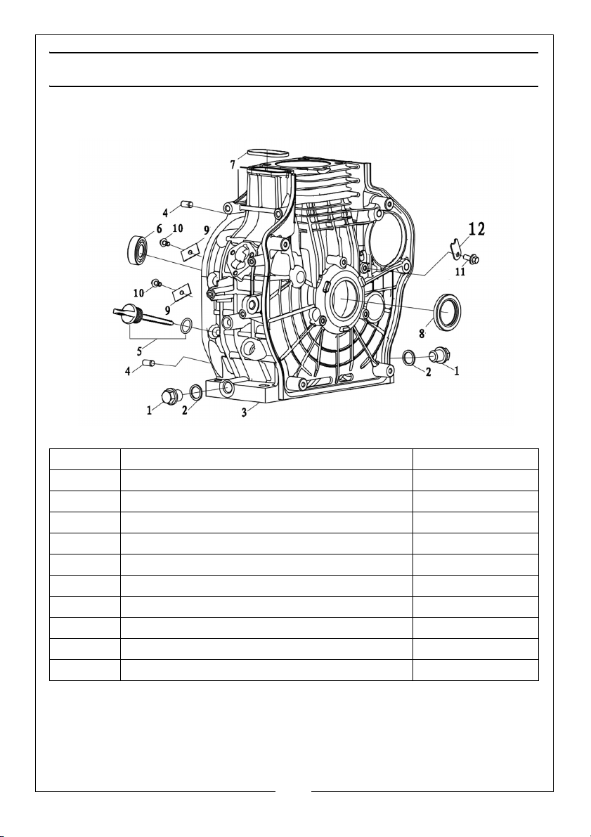
EXPLODED DIAGRAMS AND PARTS LIST
FIG 1 - CRANKCASE ASSEMBLY
NUMBER DESCRIPTION PART NUMBER
1 SEAL PLUG M16×16 ZG1102600510001
2 WASHER Ø16.5×Ø22.5×1.8 ZG3804508300001
3 CRANKCASE ZG1108102080001
4 PIN 8×16 ZG3806001690001
5 OLL FILLER CAP ASSEMBLY, ZG1106900510001
6 BEARING 6203 ZG3806300020001
7 SEAL ZG3808407920001
8 OIL SEAL 35×52×7 ZG3806503370001
9 BEARING PLATE ZG1302400040001
10 FLANGE BOLT, M8×16 ZG380140040000
18
Parts & Service: 020 8988 7400 / E-mail: [email protected] or [email protected]
Page 19
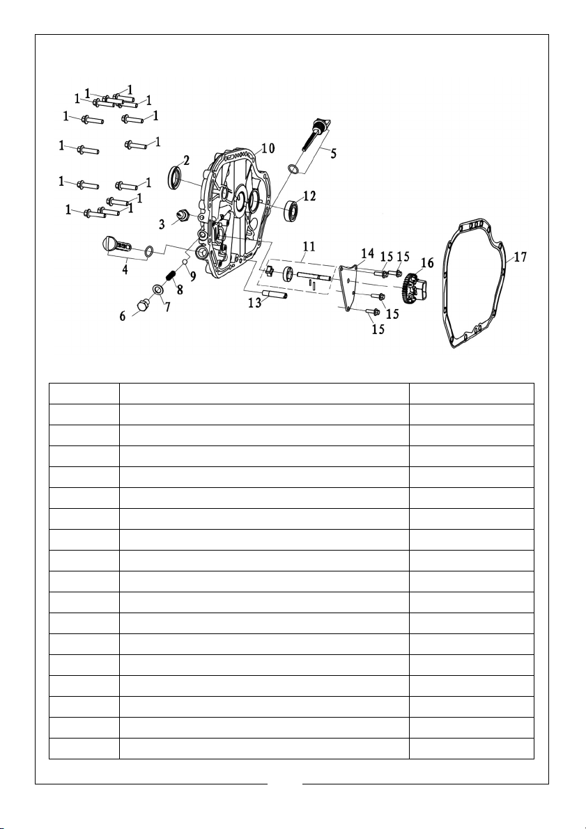
FIG 2 - CRANKCASE COVER
NUMBER DESCRIPTION PART NUMBER
1 FLANGE BOLT, M8×35 ZG3801400510005
2 OIL SEAL 30×46×8 ZG3806503360001
3 SEAL PLUG 1/8-27NPTF ZG1102600530001
4 OIL FILLER ASSEMBLY ZG1502900210001
5 OLL FILLER CAP ASSEMBLY ZG1106900510001
6 BOLT M12×16 ZG3800702880001
7 WASHER Ø12×Ø20×2 ZG3804505160001
8 COMPRESS SPRING ZG3811505140001
9 BALL ZG3806400160001
10 CRANKCASE COVER ZG1108200640001
11 OIL PUMP ZG1500100680001
12 BEARING 6203 ZG3806300020001
13 PIPE INLET OIL ZG3807801230001
14 OIL PUMP PLATE ZG1500400290001
15 FLANGE BOLT, M6×20 ZG3801400030005
16 GOVERNOR GEAR ASSEMBLY ZG1717500180001
17 CRANKCASE GASKET, COVER ZG1108300420001
19
Parts & Service: 020 8988 7400 / E-mail: [email protected] or [email protected]
Page 20
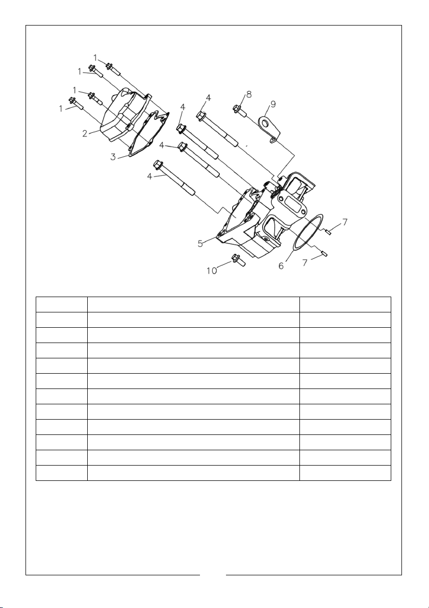
FIG 3 - CYLINDER HEAD ASSEMBLY
NUMBER DESCRIPTION PART NUMBER
1 FLANGE BOLT, M6×25 ZG3801401020004
2 CYLINDER HEAD COVER COMP ZG1202200400001
3 CYLINDER GASKET, HEAD COVER ZG1202500310001
4 HEAD BOLT, M10×1.25×90 ZG3801405960001
5 CYLINDER HEAD COMP ZG1200805280001
6 CYLINDER GASKET ZG1201501530001
CYLINDER GASKET ZG1201501900001
CYLINDER GASKET ZG1201501910001
7 PIN 4×12 ZG3806001670001
8 FLANGE BOLT, M8×20 ZG3801400040004
9 LIFTING EYE ZG1205500050001
20
Parts & Service: 020 8988 7400 / E-mail: [email protected] or [email protected]
Page 21
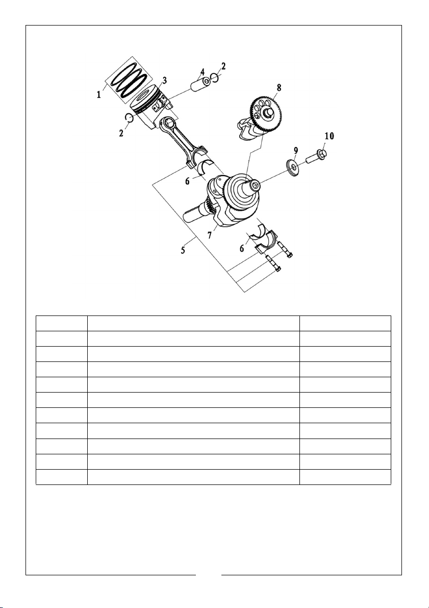
FIG 4 - CONNECTING RODS AND CRANKSHAFT
NUMBER DESCRIPTION PART NUMBER
1 RING SET ZG1300701380001
2 PISTON PIN CLIP ZG3805600920001
3 PISTON ZG1300301570001
4 PISTON PIN ZG1300600580001
5 CONN ROD ASSEMBLY ZG1301500830001
6 CRANK PIN SHELL ZG1102800070001
7 CRANKSHAFT COMP.(A) ZG1302904520001
8 BALANCE SHAFT ZG1304300180001
9 WASHER Ø13×Ø38×3.5 ZG3804507020001
10 BOLT M12×12.5×35 ZG3801404570001
21
Parts & Service: 020 8988 7400 / E-mail: [email protected] or [email protected]
Page 22
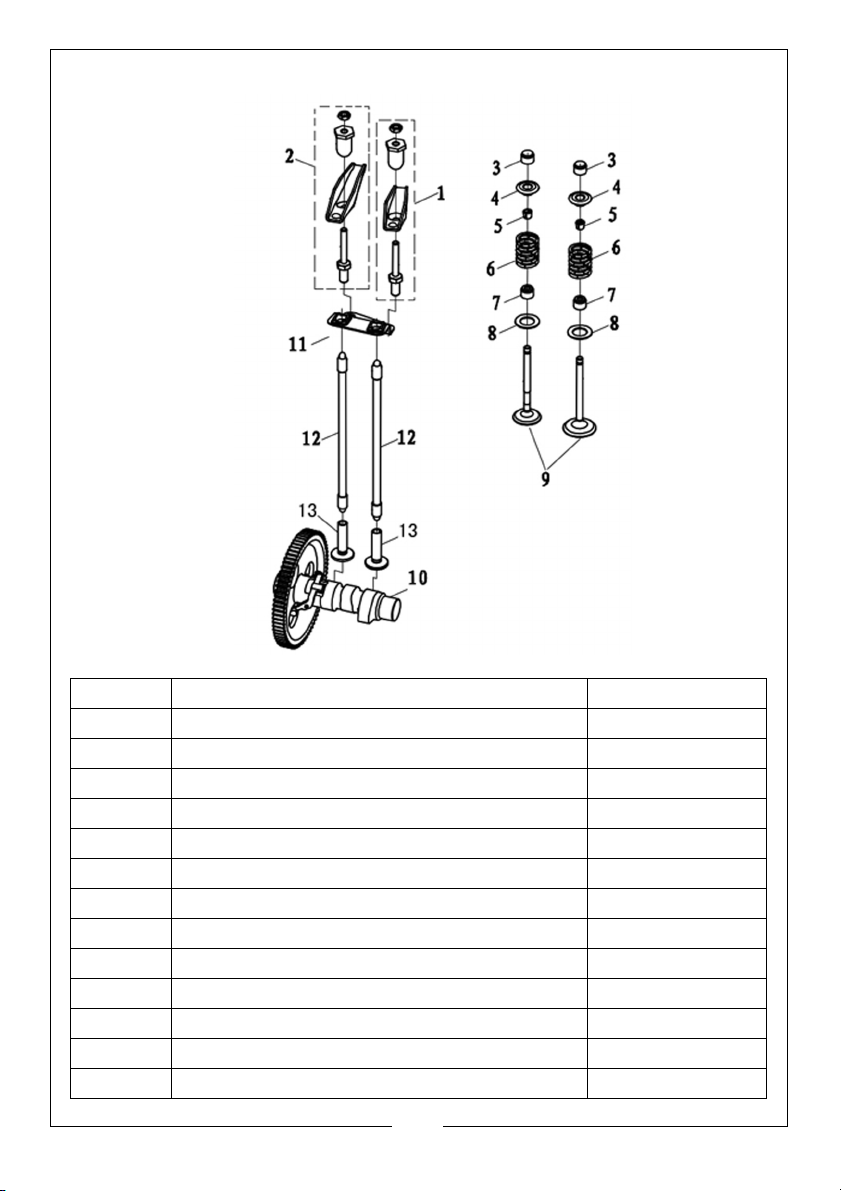
FIG 5 - VALVE TRAIN
NUMBER DESCRIPTION PART NUMBER
1 INTAKE ROCKER ARM ASSEMBLY ZG1404500420001
2 EXHAUST ROCKER ARM ASSEMBLY ZG1404500430001
3 VALVE CAP EXHAUST ZG1403200070001
4 SEAT, VALVE ZG1403800360001
5 VALVE LOCK CLAMP ZG1403900260001
6 VALVE SPRING ZG1403400350001
7 VALVE STEM SEAL ZG1404000220001
8 VALVE SEAT BOTTOM ZG1403600140001
9 VALVE KIT ZG5005500400001
10 CAMSHAFT COMP ZG1400201450001
11 GUIDE VALVE PLATE ZG1407200080001
12 PUSH ROD COMP ZG1406700240001
13 TAPPET VALVE ZG1406900200001
22
Parts & Service: 020 8988 7400 / E-mail: [email protected] or [email protected]
Page 23
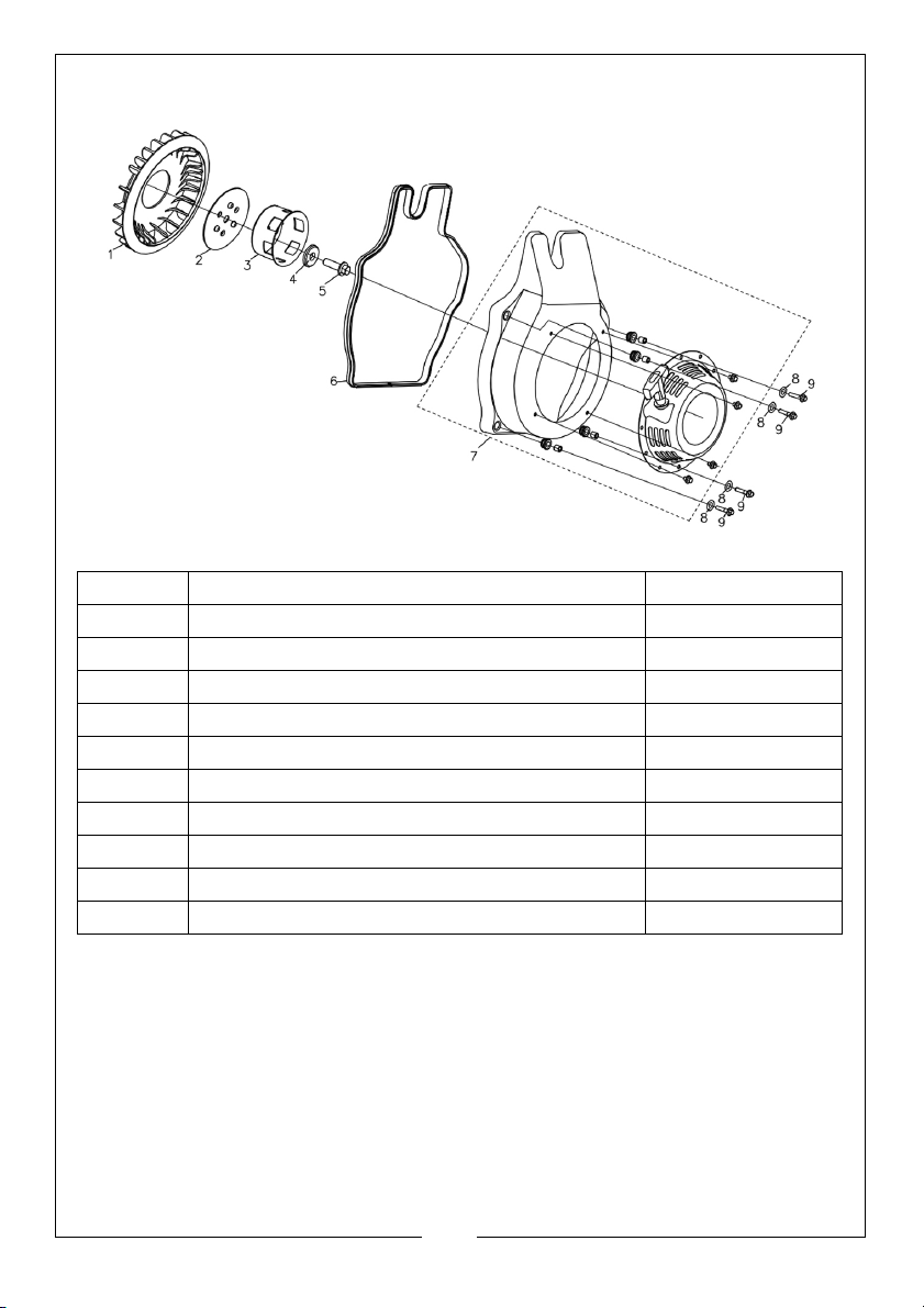
FIG 6 - PULLSTART ASSEMBLY
NUMBER DESCRIPTION PART NUMBER
1 FAN ZG1601800270001
2 FAN PLATE ZG6608800020001
3 CUP STARTER ZG1935900190001
4 WASHER Ø13×Ø38×3.5 ZG3804507020001
5 BOLT M12×12.5×35 ZG3801404570001
6 SEAL ZG3808407580001
7 PULLSTART ASSEMBLY ZG1934901560001
8 WASHER Ø6×Ø18×1.2 ZG3804508280001
9 FLANGE BOLT, M6×30 ZG3801400950005
10 FLYWHEEL ZG2700202270001
23
Parts & Service: 020 8988 7400 / E-mail: [email protected] or [email protected]
Page 24
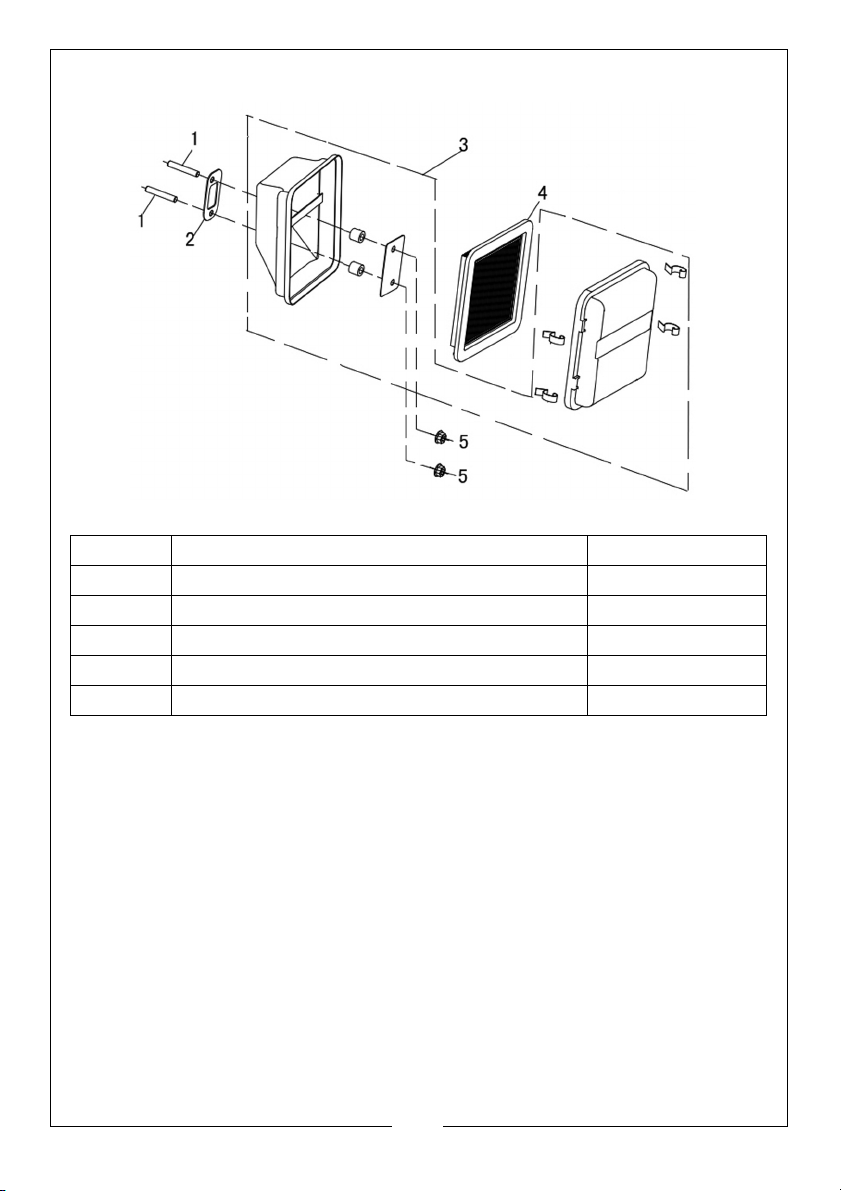
FIG 7 - AIR CLEANER
NUMBER DESCRIPTION PART NUMBER
1 STUD M8×47 ZG3801801490001
2 GASKET ZG1830000010001
3 AIR CLEANER ASSEMBLY ZG1800205340001
4 PAPER ELEMENTS ZG1801302170001
5 NUT M8 ZG3803700740002
24
Parts & Service: 020 8988 7400 / E-mail: [email protected] or [email protected]
Page 25
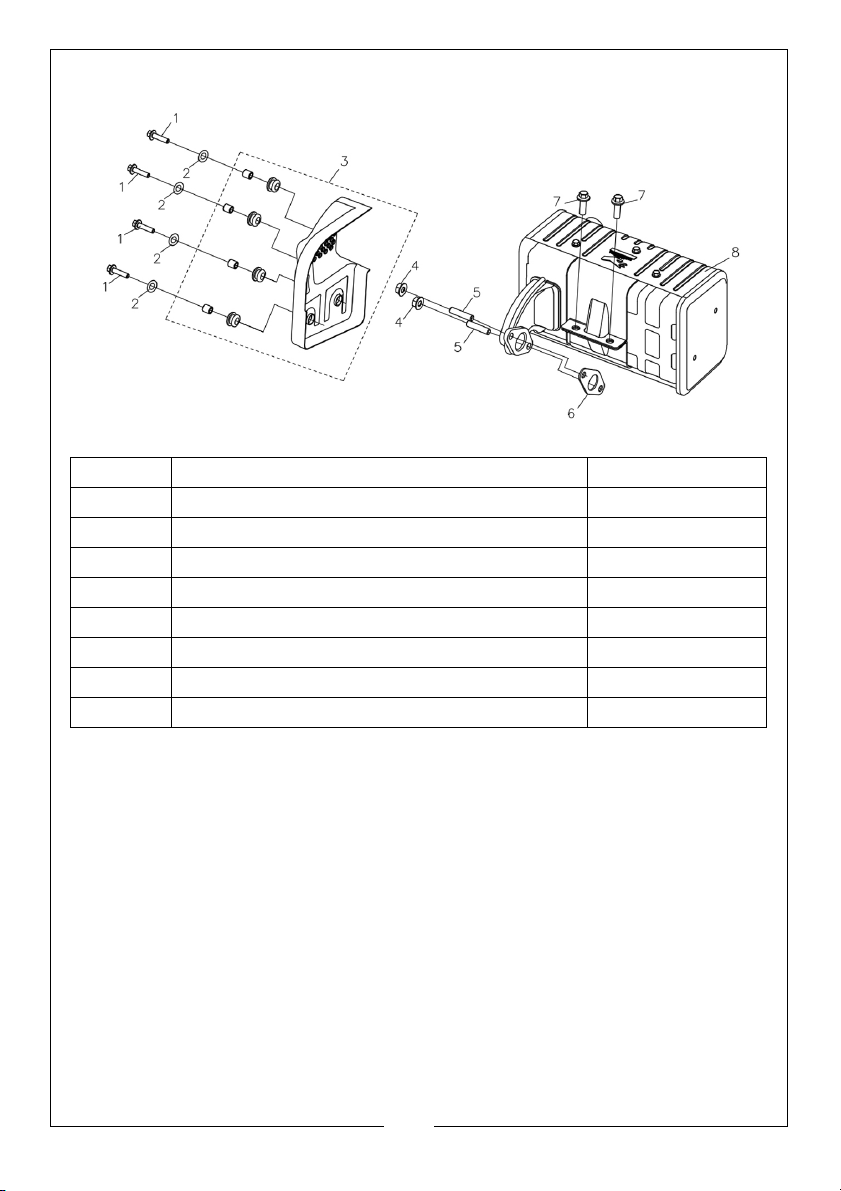
FIG 8 - MUFFLER
NUMBER DESCRIPTION PART NUMBER
1 FLANGE BOLT, M6×25 ZG3801401020004
2 WASHER Ø6×Ø18×1.2 ZG3804508280001
3 AIR CONDUCTION COVER ZG1601900510001
4 NUT M8 ZG3803400050005
5 STUD M8×34 ZG3801800980001
6 MUFFLER GASKET ZG1806600640001
7 FLANGE BOLT, M8×20 ZG3801400040004
8 MUFFLER ZG1805712990001
25
Parts & Service: 020 8988 7400 / E-mail: [email protected] or [email protected]
Page 26
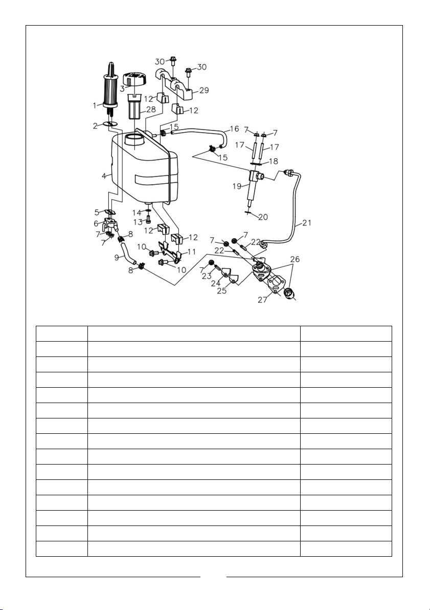
FIG 9 - FUEL SYSTEM
NUMBER DESCRIPTION PART NUMBER
1 FUEL FILTER ZG1700100300001
2 FUEL SEAL ZG6603100190001
3 CAP ZG1708700890001
4 FUEL TANK ZG1705008000001
5 FUEL TAP SEAL ZG1710200320001
6 FUEL TAP ASSEMBLY ZG1709800920001
7 FLANGE NUT, M6 ZG3803700660001
8 LATHE DOG COMP.Ø13 ZG3809601980001
9 TUBE ZG3807504860001
10 FLANGE BOLT, M8×20 ZG3801400040004
11 FUEL TANK BRACKET ZG3015600170001
12 RUBBER BUSH ZG1707001410001
13 SEAL PLUG M12×1.25×14 ZG1102600560001
14 WASHER Ø12.5×Ø20×2 ZG3804509160001
26
Parts & Service: 020 8988 7400 / E-mail: [email protected] or [email protected]
Page 27
15 HOSE CLIP ZG3809601700002
16 TUBE ZG3807504870001
17 STUD M6×54 ZG3801801380001
18 PLATE INJECTOR ZG1741800010001
19 INJECTOR ZG1730100040001
20 WASHER Ø8×Ø16.5×0.5 ZG3804508290001
21 TUBE ZG3807504710001
22 STUD M6×38 ZG3801801370001
23 STUD M6×38 ZG3801801450001
24 FUEL PUMPPLATE ZG1741600010001
25 FUEL PUMP GASKET ZG1741700010001
26 FUEL PUMP ZG1741300010001
27 FUEL PUMP GASKET ZG1741400010001
FUEL PUMP GASKET ZG1741400010002
FUEL PUMP GASKET ZG1741400010003
28 FUEL FILTER ZG1707200100001
29 FUEL TANK SUPPORT ZG3015600160001
30 FLANGE BOLT, M8×40 ZG3801400050006
27
Parts & Service: 020 8988 7400 / E-mail: [email protected] or [email protected]
Page 28
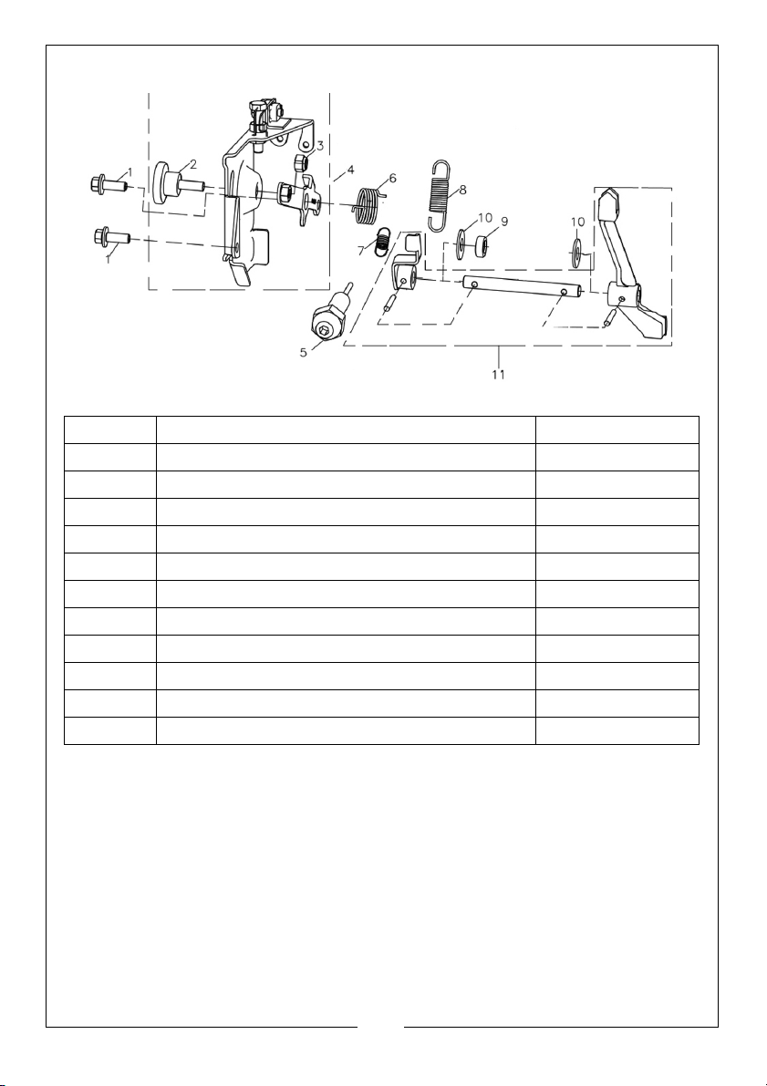
FIG 10 - GOVERNOR SYSTEM
NUMBER DESCRIPTION PART NUMBER
1 FLANGE BOLT, M6×14 ZG3801402150003
2 KNOB CONTROL ZG171340029T270
3 NON- METAL HEXAGON NUTS M6 ZG3803500080001
4 CONTROL ASSEMBLY ZG1715800190001
5 FUEL STOP ASSEMBLY ZG1742300010001
6 TORSIONAL SPRING ZG3811601500001
7 SPRING ZG3811404780001
8 GOVERNOR SPRING ZG1716000420001
9 OIL SEAL 8×14×5 ZG3806503770001
10 WASHER Ø8.5×Ø15.8×2 ZG3804505920001
11 FORK ZG1945300050001
28
Parts & Service: 020 8988 7400 / E-mail: [email protected] or [email protected]
Page 29
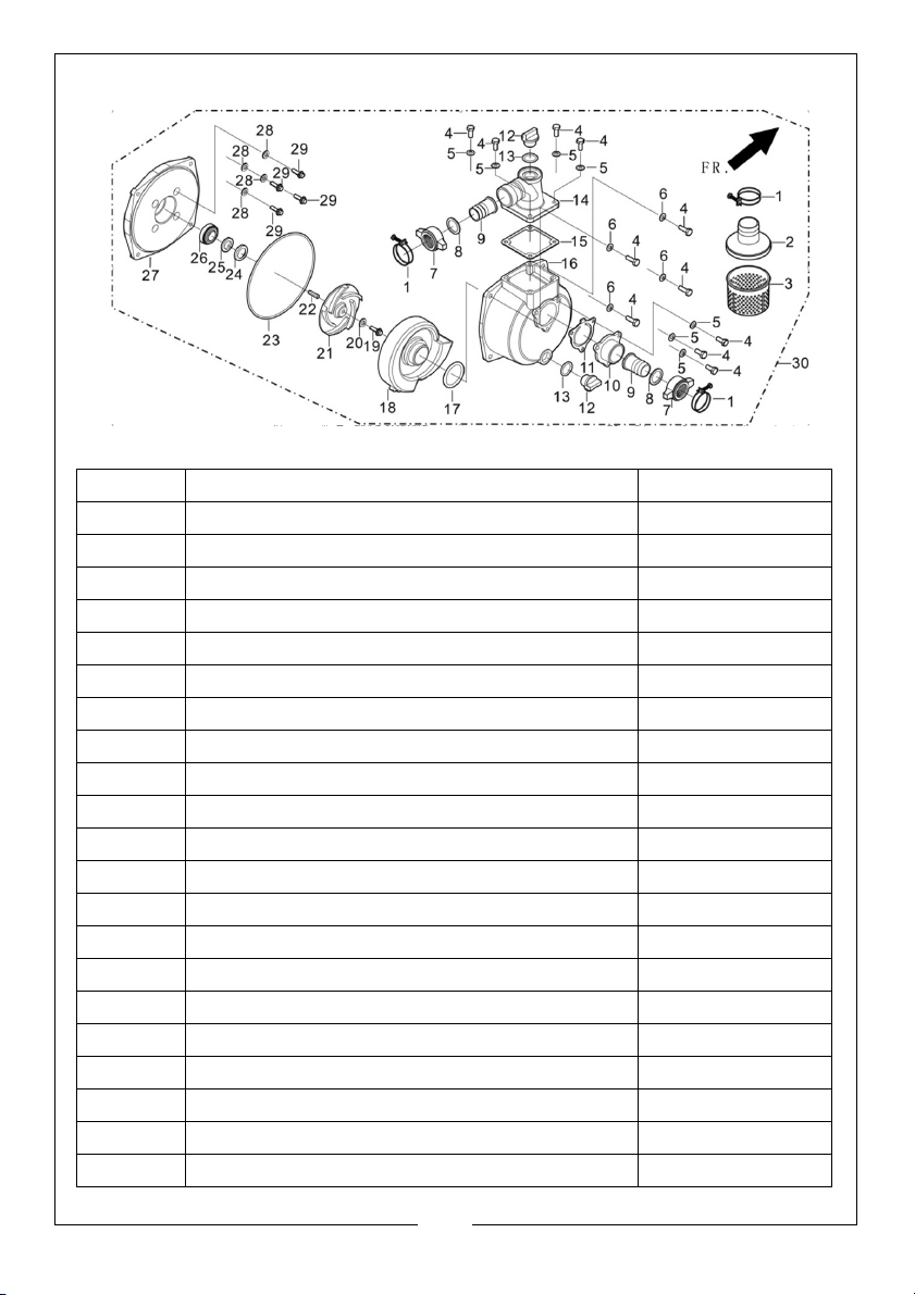
FIG 11 - PUMP
NUMBER DESCRIPTION PART NUMBER
1 HOOP ASSY, HOSE ZG70400V010110
2 COVER, FILTER ZG70113V010110
3 FILTER ZG70114V010110
4 BOLT ZG90001082501
5 WASHER ZG90409V010110
6 WASHER ZG90408080001
7 PIPE CONNECTING FLANGE ZG70115V010110
8 JOINT WASHER ZG70118V010110
9 CONNECTOR ZG70117V010110
10 INLET, WATER ZG70116V010210
11 GASKET? INLET WATER ZG70109V010110
12 PLUG, THREAD ZG70107V010110
13 WASHER, SCREW PLUG ZG70122V010110
14 OUTLET? WATER ZG70108V010210
15 GASKET? OUTLET ZG70109V010110
16 PUMP BODY ZG70105V010110
17 RIGN?WHORL CASE SEALING ZG70104V010110
18 CASE, WHORL ZG70103V010110
19 BOLT ZG90001V010110
20 WASHER ZG90409V010110
21 IMPELLER, WATER PUMP ZG70102V010210
29
Parts & Service: 020 8988 7400 / E-mail: [email protected] or [email protected]
Page 30
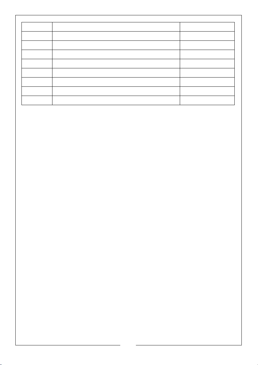
22 KEY ZG90522V010110
23 CUSHION, WATER PUMP JOINT ZG70119V010110
24 IMPELLER SEAL ZG70125V010110
25 SEAL,PORCELAIN ZG70309V010110
26 SEAL ASSY, MECHANISM ZG70300V010110
27 JOINT, WATER PUMP ZG70118V010210
28 WASHER ZG90409V010110
28 BOLT ZG90001V010210
30 PUMP ASSY, WATER ZG70100V011410
30
Parts & Service: 020 8988 7400 / E-mail: [email protected] or [email protected]
Page 31
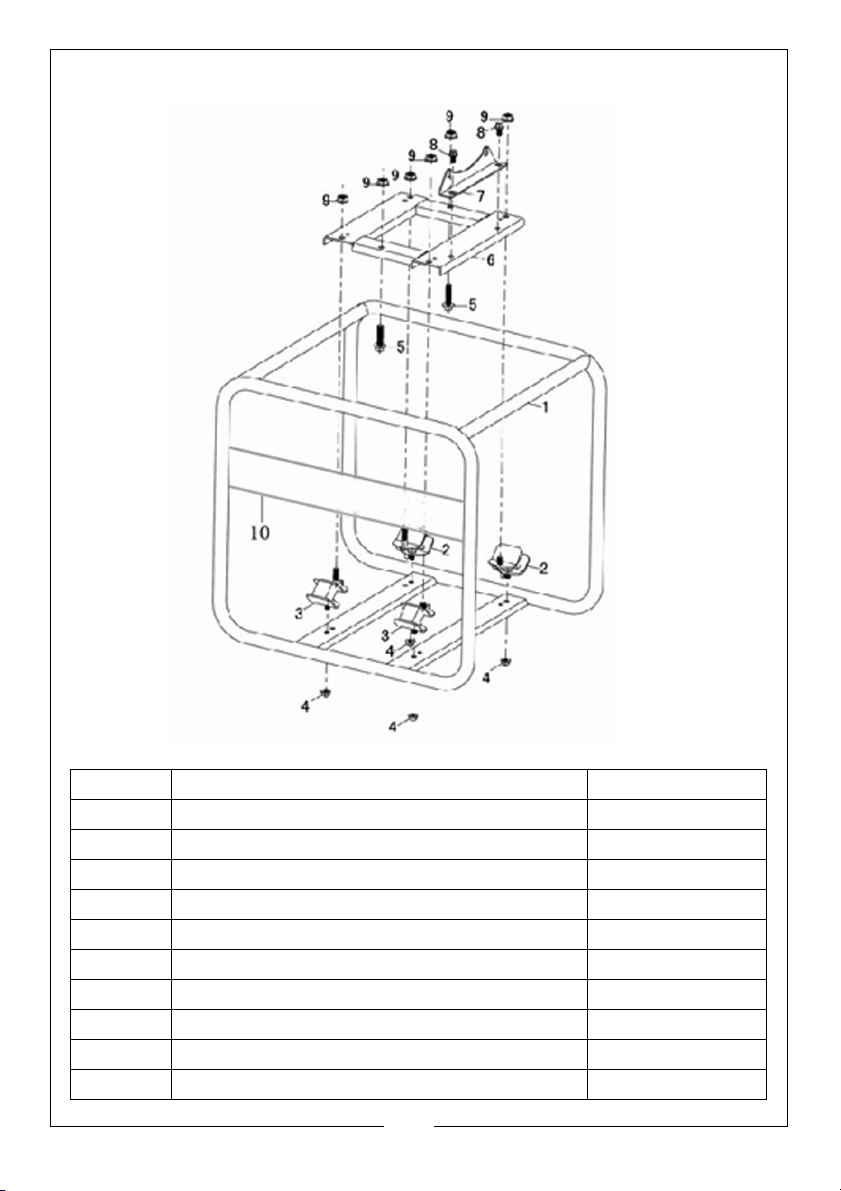
FIG 12 - FRAME
NUMBER DESCRIPTION PART NUMBER
1 FRAME COMPLETE ZG3007204230001
2 RIGHT BOTTOM RUBBER,L=15 ZG3007900060001
3 RIGHT BOTTOM RUBBER ZG3007900020001
4 FLANGE NUT ZG3803700070004
5 FLANGE BOLT ZG3801401260004
6 RUBBER SETTING ZG3008000350001
7 BRACKET ZG3462800050001
8 FLANGE BOLT ZG3801400400005
9 FLANGE NUT ZG3803700770001
10 PROTECTIVE DIAPHRAGM ZG3803700120003
31
Parts & Service: 020 8988 7400 / E-mail: [email protected] or [email protected]
Page 32
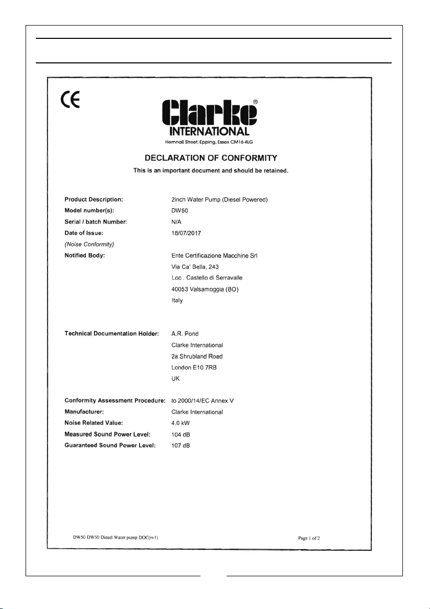
DECLARATION OF CONFORMITY
32
Parts & Service: 020 8988 7400 / E-mail: [email protected] or [email protected]
Page 33
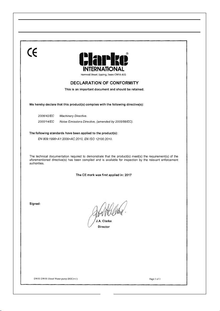
DECLARATION OF CONFORMITY
33
Parts & Service: 020 8988 7400 / E-mail: [email protected] or [email protected]
Page 34

Page 35

Page 36
 Loading...