

Page 1
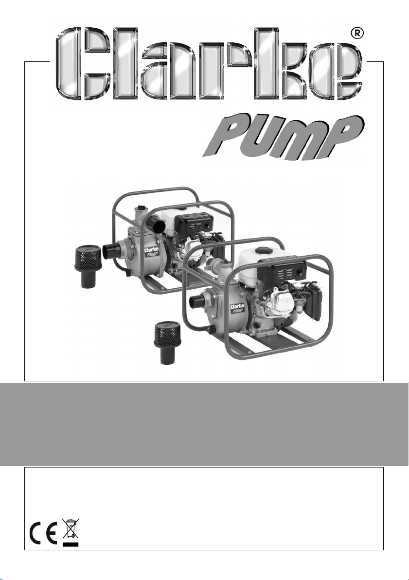
PETROL DRIVEN WATER PUMP
MODEL NO: PW2 & PW3
PART NO: 7140640 & 7140645
OPERATION & MAINTENANCE
INSTRUCTIONS
ORIGINAL INSTRUCTIONS GC0317
Page 2
INTRODUCTION
Thank you for purchasing this CLARKE water pump.
Before attempting to use the pump, please read this manual thoroughly and
follow the instructions carefully. In doing so you will ensure the safety of yourself
and that of others around you, and you can look forward to the pump giving
you long and satisfactory service.
GUARANTEE
This CLARKE product is guaranteed against faulty manufacture for a period of
12 months from the date of purchase. Please keep your receipt as proof of
purchase.
This guarantee is invalid if the product is found to have been abused or
tampered with in any way, or not used for the purpose for which it was
intended.
Faulty goods should be returned to their place of purchase, no product can
be returned to us without prior permission.
This guarantee does not effect your statutory rights.
ENVIRONMENTAL RECYCLING POLICY
Through purchase of this product, the customer is taking on the
obligation to deal with the WEEE in accordance with the WEEE
regulations in relation to the treatment, recycling & recovery and
environmentally sound disposal of the WEEE.
In effect, this means that this product must not be disposed of with general
household waste. It must be disposed of according to the laws governing
Waste Electrical and Electronic Equipment (WEEE) at a recognised disposal
facility.
If disposing of this product or any damaged components, do not dispose of
with general waste. This product contains valuable raw materials. Metal
products should be taken to your local civic amenity site for recycling of metal
products.
2
Parts & Service: 020 8988 7400 / E-mail: [email protected] or [email protected]
Page 3
SAFETY PRECAUTIONS
CAUTION: As with all machinery, there are certain hazards involved
with its operation and use. Exercising caution will reduce the risk of
personal injury.
1. Always observe all safety precautions for the handling of fuel.
2. Thoroughly familiarise yourself with this unit & its operation, and follow all
instructions in this manual.
3. Always ensure that the pump is properly positioned where necessary to
prevent it from moving during operation, and that the immediate area
surrounding the pump is kept clear.
4. Always ensure the unit cannot be started inadvertently by using the ON/
OFF switch whenever carrying out maintenance or making adjustments.
5. Always use the strainer connected to the suction hose to prevent stones
and other solids from being drawn up, which could cause severe damage
to the pump.
6. Always keep the machine itself dry and well clear of water discharge
7. Always use only replacement parts supplied by the manufacturer. The use
of non-standard parts could be hazardous.
8. Always use at least 1ft (30cm) of flexible hose to make pipe connections to
the pump. Rigid piping may put stress on the pump, causing damage. If
rigid piping is used, it should be supported so as to eliminate stress.
9. Never refuel the engine whilst it is running, and allow the engine to cool
sufficiently before refuelling.
10. Never use for pumping petrol (or other flammable liquids), or corrosive
chemicals. These pumps are designed to pump water only.
11. Never operate an engine driven unit in an explosive atmosphere, near
combustible materials, or where there is insufficient ventilation.
12. Never allow children to use this pump.
13. Never run the pump dry. Always fill the pump with water before starting.
14. Never attempt any major repairs to this product unless you are qualified.
15. Never direct the discharge flow towards another person.
16. Never over-tighten drain or filler plugs. Excessive force may damage the
threads or the pump body.
17. Never direct the water discharge towards electrical wiring or equipment.
3
Parts & Service: 020 8988 7400 / E-mail: [email protected] or [email protected]
Page 4
OVERVIEW
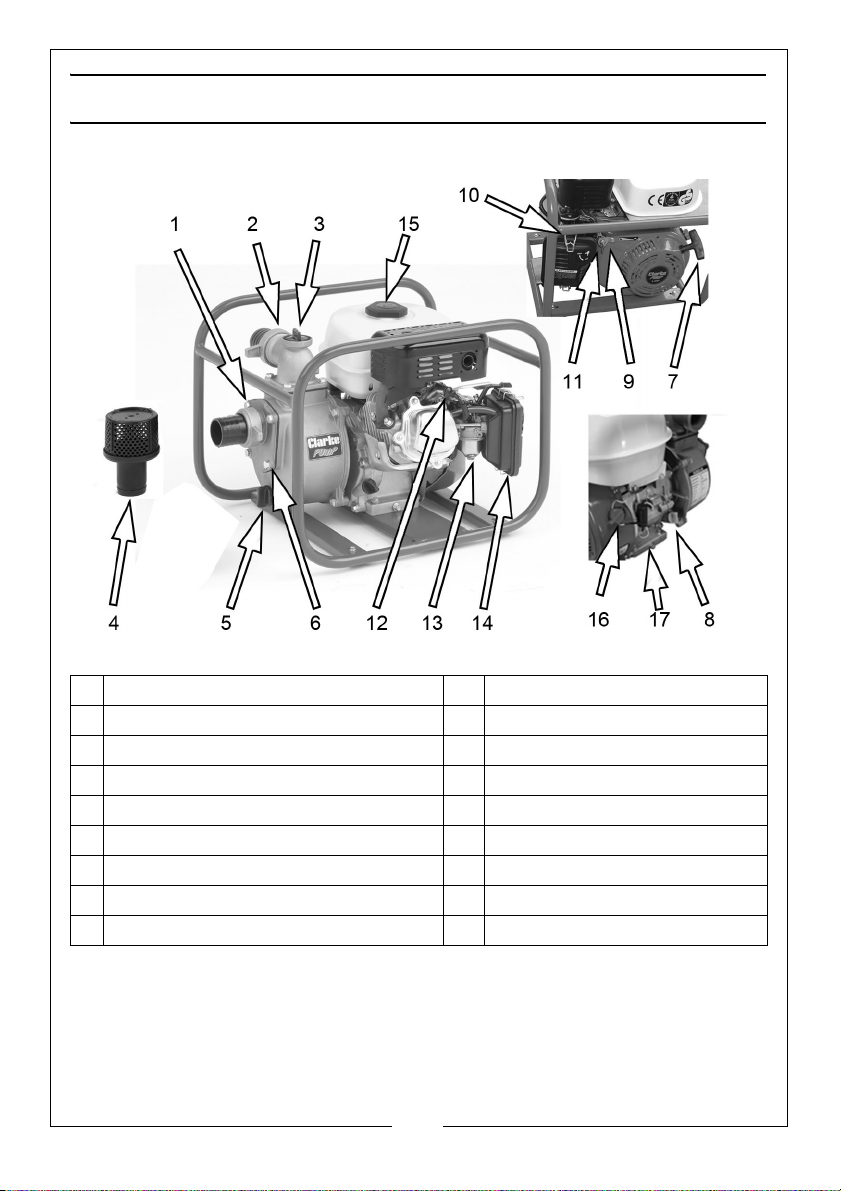
1 Inlet or Suction Chamber 10 Choke Lever
2 Output or Discharge Pipe 11 Throttle Lever
3 Water Filler Plug 12 Spark Plug
4 Inlet Strainer 13 Carburetor Drain Plug
5 Suction Chamber Drain Plug 14 Air Filter Housing
6 Suction Chamber Bolt 15 Fuel Filler Cap
7 Starter Recoil 16 ON/OFF Switch
8 Oil Filler and Dipstick 17 Oil Drain Plug
9 Fuel Shut-off Valve (cock)
The PW2/PW3 petrol driven pumps are designed for pumping clean water, or
water containing small solids in suspension. The pumps are fitted with an open
impeller. The suction strainer supplied must always be used to ensure that large
stones or other objects cannot be drawn up, as this would cause severe
damage to the pump. The images may show a PW3 pump although PW2
pumps are similar.
4
Parts & Service: 020 8988 7400 / E-mail: [email protected] or [email protected]
Page 5
BEFORE USE
REMEMBER: Contaminated water is water containing small solids in suspension,
NOT slurry, sludge, sand or mud.
Place the pump on a firm foundation as near to the water source as possible.
Ensure there is adequate drainage for the discharged water and that there is
no danger of damage to property as a result of water being dischaged.
ADDING OIL
This pump is supplied without engine oil or fuel. Use any engine oil of SAE 10-30
rating unless operating at very high or low ambient temperatures.
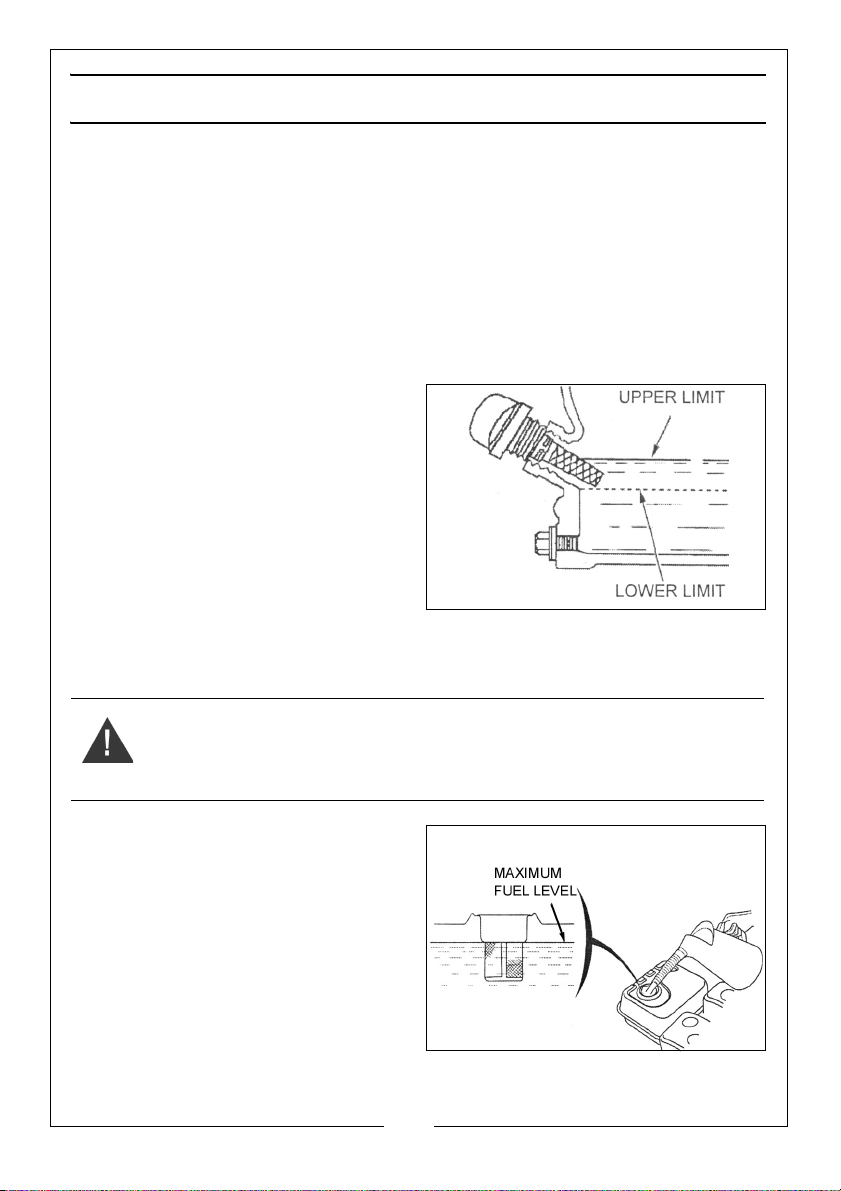
Fill the engine crankcase with oil as
follows:
1. Remove the filler plug/dipstick.
2. Fill with oil until visible inside.
3. Check the level by inserting the
dipstick back into the filler neck
and checking the level is within
the indicated range. If correct
replace the dipstick/filler cap.
NOTE: The pump is fitted with a low oil sensor which will stop the engine if the
oil level drops below the safe level to avoid internal damage. Refer to
troubleshooting section.
WARNING: WIPE UP ANY SPILT FUEL BEFORE RUNNING THE PUMP.
ALLOW THE ENGINE TO COOL DOWN BEFORE REFUELLING
ADDING FUEL
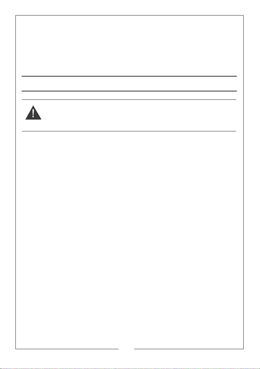
Use unleaded petrol with a pump
octane rating of 86 or higher.
1. Fill the fuel tank with unleaded
petrol or check the level by
opening the fuel cap and topping
up as required. Located within the
fuel tank is a strainer. Check this
filter periodically and remove any
contaminants which may have
accumulated. Do not fill above the fuel strainer shoulder. After refuelling,
tighten the fuel filler cap securely.
5
Parts & Service: 020 8988 7400 / E-mail: [email protected] or [email protected]
Page 6

GENERAL USE OF THE PUMP
1. Connect the suction and discharge hoses to the pump housing using the
hose clamps and gaskets supplied to achieve an airtight seal. There must
be no damage of any kind to the hoses which must be well protected and
supported.
NOTE: Hoses or pipes should be supported independently and not have their
weight carried by the pump.
IMPORTANT: An air leak in the suction line will prevent priming, and reduce
the capacity of the pump.
2. Pay particular attention to the following:
• Always ensure the hose adaptor gasket is in place and correctly fitted.
• Always use a flexible hose at the pump body connection of at least 1ft
(300mm).
• Keep all pipes/hoses as short and straight as possible and avoid sharp
bends.
• If a flexible hose must be laid across a roadway, protect it with planking.
• Ensure there is adequate drainage for the water being dischaged.
Instantaneous shut off pressure, applied when a vehicle runs across an
unprotected hose, will cause “hydraulic shock”, which can damage the
pump and/or the hose).
3. Attach the suction strainer to the end of suction hose using a further hose
clamp to prevent large stones etc, from being drawn up which could
cause severe damage. Keep the strainer clean. If it is likely to clog with dirt
or debris, proceed by either:
• Preparing a bed of stones on which to rest the strainer.
• Tying the strainer so that it stays off the bottom of the pit, pond or
excavation.
• Tie the strainer inside a basket or bucket.
4. Remove the filler plug on top of the pump case and prime the pump with
water, leaving no air gap. Remember the pump is self-priming only when
the pump is filled. It will prime and re-prime itself without refilling. Refilling is
necessary only if the pump has been drained or if the water has been lost.
Never allow the pump to run dry.
5. If the discharge line runs vertically more than 30ft it is advisable to install a
check valve in the discharge line near the pump to stop destructive water
hammer when the pump is shut down. If a check valve is installed, it may
6
Parts & Service: 020 8988 7400 / E-mail: [email protected] or [email protected]
Page 7
also be necessary to vent the top of the pump so that air can he expelled
during automatic re-priming. This air bleed may he accomplished by
providing a 1/4" line from the top of the pump back to the liquid source.
Clarke International will not assume any responsibility for damage to the
pump if no check valve is used in the discharge line.
Properly fuelled and lubricated your pump will run without attention.
OPERATION
WARNING: WHEN THE ENGINE IS RUNNING THE EXHAUST MUFFLER IS VERY
HOT. TAKE CARE TO AVOID BURNS. NEVER RUN THE ENGINE IN AN
ENCLOSED SPACE - ENSURE THERE IS ADEQUATE VENTILATION.
Ensure the site and pump are prepared as detailed on page 6, then proceed
as follows:.
PRIMING & CONTROL
1. With the fuel cock open, pull the starter recoil rope slowly two or three
times to allow fuel to reach the carburettor.
2. To start a cold engine, set the choke lever to the closed position, but if the
engine is already warm the choke should be in the open position.
3. Set the throttle about one third open. Turn the engine switch to ON.
4. Pull the starter recoil rope firmly until the engine starts. Do not snatch at the
starter rope and allow it to retract slowly after each pull.
5. Once the engine starts, gradually return the choke to the open position as
the engine warms up and use the engine throttle to gradually increase
engine speed.
STARTING
After starting the engine, move the throttle to the open position for priming of
the pump and checking for pump output. Output is controlled by adjusting
the engine speed.
NOTE: With a suction lift of 5 to 10ft, the pump should begin discharging liquid
in less than a minute. A lift of 25ft (at sea level) should require not more
than 2 minutes for initial prime. To further reduce priming time the
engine speed may be increased, after the engine is properly run in. If
pumping does not start within this time, shut off engine and check
carefully to find the problem. (See TROUBLESHOOTING on page 10).
7
Parts & Service: 020 8988 7400 / E-mail: [email protected] or [email protected]
Page 8
NOTE: Filling the suction pipe with water will speed up the priming process,
and it is recommended that a non-return valve be fitted to the end of
the suction pipe.
On higher vertical lifts, a higher engine speed is necessary but on shallow lifts
or when there is little water to pump, preserve fuel and engine wear by
reducing engine speed.
In the event of blockages, where debris has entered the suction chamber, this
can be opened and cleaned out by removing the bolts shown in the layout
on page 4.
SHUTTING DOWN
1. Gradually reduce engine speed to minimum using the throttle lever.
2. Stop the engine by switching OFF the ignition switch.
3. Close the fuel cock.
MAINTANENCE
1. Always maintain the pump in a clean condition, checking regularly for
loose bolts etc.
2. Clean the air filter once every 50 hours of use (or more often in unusually
dusty conditions) as follows. Clean the foam filter element with domestic
detergents and clean the mesh element by knocking against a solid
object or blow out any dust with a high pressure air jet. Never operate the
pump without the air cleaner installed as this would cause premature wear
to the engine.
3. Replace the spark plug after the first month or every 50 hours of use. Check
when installing that the spark plug has the correct clearance by measuring
with a feeler gauge and adjusting the side electrode as required.
• Clearance should be 0.70-0.80mm.
• The recommended spark plug for both the PW2 and PW3 pump is
“Torch/F6RTC”.
8
Parts & Service: 020 8988 7400 / E-mail: [email protected] or [email protected]
Page 9
CHANGING THE OIL
The oil in the engine should be changed after the first 20 hours use and
thereafter every 6 months or 100 running hours. Remove the dipstick and drain
plug and then drain the oil. Re-fill and check the level as described on page 5.
CAUTION: PROLONGED EXPOSURE TO USED OIL IS HARMFULL. ALWAYS
WASH YOUR HANDS THOROUGHLY AFTER HANDLING USED OIL.
ENVIRONMENTAL PROTECTION
One of the most damaging sources of pollution is oil. Do not throw away used
oil with domestic refuse or flush down a sink or drain. Collect old oil in a leakproof container and take it to your local waste disposal site.
STORAGE & HANDLING
After use, drain the pump body whenever there is danger of freezing. If the
pump has been used with contaminated or salty water it should be thoroughly
flushed with clean water following use, both inside and out and drained
before replacing the drain plug. Always transport the pump with the fuel cock
turned off and keep the unit level to prevent any fuel from spilling.
If the pump is not to be used for some time it should be flushed thoroughly with
clean water and drained completely before storing in a clean dry
environment. Additionally, it should be prepared as follows:
1. Drain the fuel tank and carburettor completely by opening the drain plug
in the carburettor float chamber and draining all remaining fuel into a
suitable container ensuring the fuel shut-off valve is open.
2. Remove the spark plug, and pour 2-3 teaspoons of light oil into the cylinder
through the spark plug hole.
3. Pull the starter recoil rope slowly 2 or 3 times so that the oil is deposited on
the cylinder walls and replace the spark plug.
4. For longer term storage, use the starter to turn the engine until the triangle
mark on the starter wheel lines up with the starter screw hole. In this
location both the inlet and exhaust valves are closed which may prevent
the engine from suffering internal corrosion during storage.
9
Parts & Service: 020 8988 7400 / E-mail: [email protected] or [email protected]
Page 10
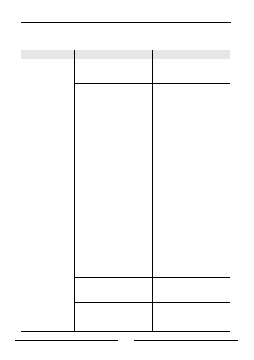
TROUBLESHOOTING
Problem Cause Solution
Engine fails to start Lack of fuel in the tank Fill the tank as necessary
Engine stops and
will not restart.
Pump fails to
prime
No fuel reaching the
carburetor
Engine switch is in the Off
position
Lack of spark at the spark
plug.
Lack of oil in engine causing
‘Low Oil Protection’ sensor
to stop engine from running.
Priming chamber not filled
correctly.
Air leaks through the suction
line joints (damaged hose,
broken hose clamps, broken
/ ill-fitting gasket).
Blocked inlet hose. Clean strainer & ensure it is
Engine speed too low. Increase engine speed.
Damaged impeller. Renew the impeller after dis-
Air leaks through damaged
seal.
Fuel cock is isolated
Set the engine switch to the
On position.
Check that the spark plug
wire is securely attached to
the plug head. With the
switch in the ON position,
hold the spark plug side
electrode against the
engine and pull the starter
cord to observe the spark. If
a spark is present but the
engine still cannot start consult your dealer for help.
Fill the oil sump as
necessary.
Fill priming chamber leaving
no air gap.
Carry out repairs as
necessary. Check/repair
connections as required.
not submerged in mud or
sediment etc. Ensure there
are no kinks in the delivery
hose.
mantling the pump.
Renew seal.
10
Parts & Service: 020 8988 7400 / E-mail: [email protected] or [email protected]
Page 11
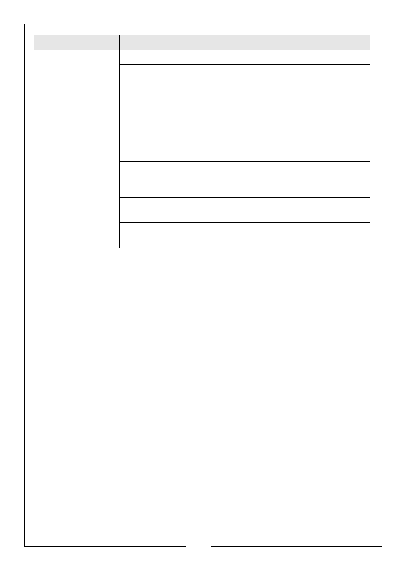
Problem Cause Solution
Low output from
pump
Engine speed too low. Increase the engine speed.
Impeller clogged Clean the strainer and
ensure it is not submerged in
mud or sediment etc.
Suction or delivery line
obstructed.
Clear any obstruction and
ensure there are no kinks in
the delivery line.
High friction losses in the
suction line.
Avoid unnecessary curves,
restrictions or valves.
Suction lift too high Set the pump as close as
possible to the level of the
liquid being pumped.
Congested material inside
pump.
Dismantle the pump and
clean out.
Damaged impeller Dismantle the pump and
renew the impeller.
11
Parts & Service: 020 8988 7400 / E-mail: [email protected] or [email protected]
Page 12
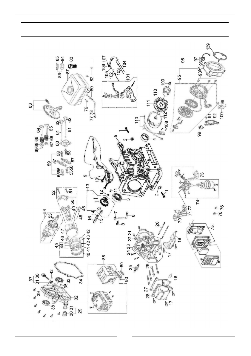
ENGINE COMPONENTS DIAGRAM
12
Parts & Service: 020 8988 7400 / E-mail: [email protected] or [email protected]
Page 13
ENGINE COMPONENTS LIST
NO DESCRIPTION NO DESCRIPTION
1 Oil Drain Plug 30 Oil Plug
2 Washer 31 Seal
3 Bearing 6205 32 Crankcase Cover
4 Crankshaft Oil Seal 33 Bearing 6205
5 Crankcase 34 Crankcase Gasket
6 Regulating Sway Bar 35 Set Pin
7Washer 36Oil Dipstick
8 Split Pin 37 Oil Dipstick Assembly
9 Oil Sensor 38 Crankshaft Oil Seal
10 Bolt M6 x 14 39 Bolt M8 x 32
11 Regulating Shaft 40 Piston Ring
12 Washer 41 Piston Ring
13 Regulator Gear Assembly 42 Side Rail
14 Snap Ring 43 Expander
15 Washer 44 Scraper Ring Set
16 Sleeve 45 Piston Ring Set
17 Bolt M6 X 12 46 Piston Pin Circlip
18 Air Duct 47 Piston
19 Wind Cover 48 Piston Pin
20 Bolt M6 x 12 49 Connecting Rod
21 Set Pin 10 x 16 50 Bearing Shell
22 Cylinder Head Gasket 51 Bolt
23 Cylinder Head Assembly 52 Connecting Rod Assembly
24 Bolt M8 x 34 53 Woodruff Key
25 Spark Plug 54 Crankshaft Assembly
26 Bolt 55 Locknut
27 Cylinder Head Cover Gasket 56 Sleeve
28 Cylinder Head Cover 57 Rocker
29 Oil Plug Assembly 58 Valve Gap Adjusting Bolt
13
Parts & Service: 020 8988 7400 / E-mail: [email protected] or [email protected]
Page 14
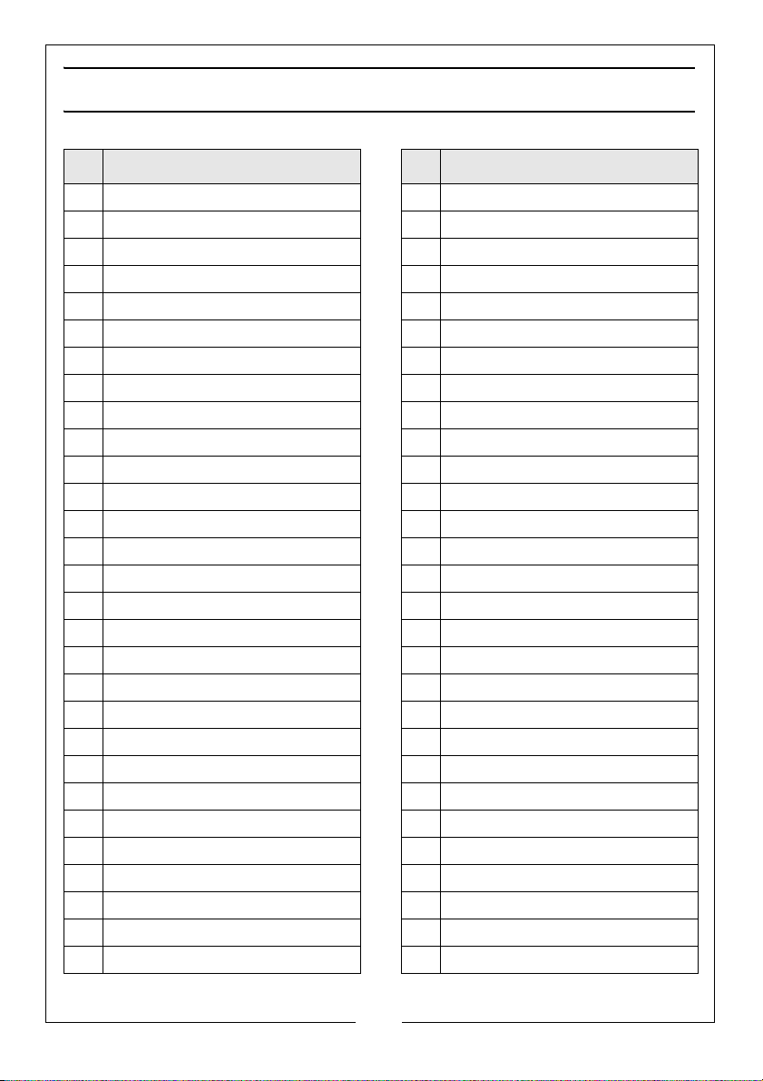
ENGINE COMPONENTS LIST (CONT)
NO DESCRIPTION NO DESCRIPTION
59 Rocker Parts Set 88 Exhaust Muffler
60 Pusher Guide 89 Exhaust Gasket
61 Pushrod 90 Nut M6
62 Tappet 91 Bolt M6 x 22
63 Camshaft Assembly 92 Crankcase Sideplate
64 Exhaust Valve 93 Bolt M6 x 8
65 Intake Valve 94 Fan Hood Assembly
66 Valve Spring 95 Recoil Starter Assembly
67 Spring Seat (Inlet Valve) 96 Bolt M6 x 12
68 Spring Seat (exhaust Valve) 97 Engine Switch
69 Collet 98 Recoil Starter Assembly
70 Gasket 99 Plastic Clip
71 Connecting Bracket 100 Diode
72 Carburetor Gasket 101 Regulating Frame
73 Air Cleaner Gasket 102 Back Spring
74 Carburetor Assembly 103 Regulating Spring
75 Air Cleaner 104 Pulling Rod
76 M6 Nut 105 Lock Bolt
77 Pipe Clamp 106 Regulating Arm
78 Outlet Pipe 107 Nut M6
79 Bolt M6 x 22 108 Screw M6 x 25
80 Pipe Connector 109 M14 nut
81 Packing Ring 110 Starting Ring
82 Nut M6 111 Fan
83 Fuel Filter Cup 112 Flywheel
84 Packing ring 113 Ignition Coil
85 Fuel cap
86 Fuel cap Assembly
87 Fuel Tank
14
Parts & Service: 020 8988 7400 / E-mail: [email protected] or [email protected]
Page 15
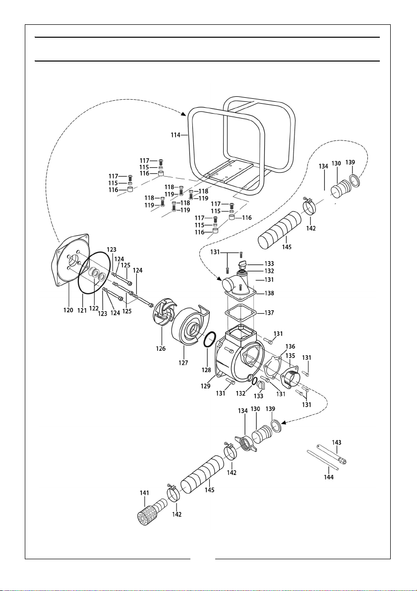
PUMP COMPONENTS DIAGRAM - PW2
15
Parts & Service: 020 8988 7400 / E-mail: [email protected] or [email protected]
Page 16
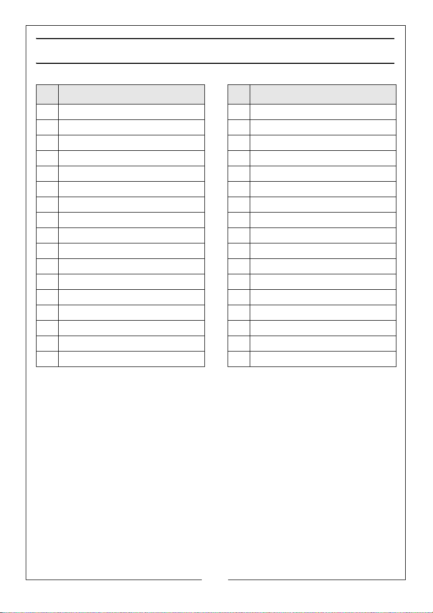
PUMP COMPONENTS LIST - PW2
NO Description NO Description
114 23” Frame sub-assembly 131 Bolt
115 Nut M6 132 O-Ring
116 Rubber Foot 133 Drain Plug
117 Bolt M6 x 12 134 2” Hose Union
118 Nut M8 135 2” Inlet Flange
119 Bolt M8 x 32 136 Gasket (inlet flange)
120 Rear Housing 137 Gasket (outlet flange)
121 O-Ring 138 2” Outlet Flange
122 Mechanical Seal 139 Gasket 2”
123 O-Ring 140 N/A
124 Copper Washer 141 Strainer
125 Allen Headed Bolt 142 Jubillee Clip
126 Impeller 143 Spark Plug Wrench (short)
127 Impeller Cover 144 Extension Bar
128 O-Ring 145 Water Hose (not supplied)
129 Front Housing
130 2” Pipe
16
Parts & Service: 020 8988 7400 / E-mail: [email protected] or [email protected]
Page 17
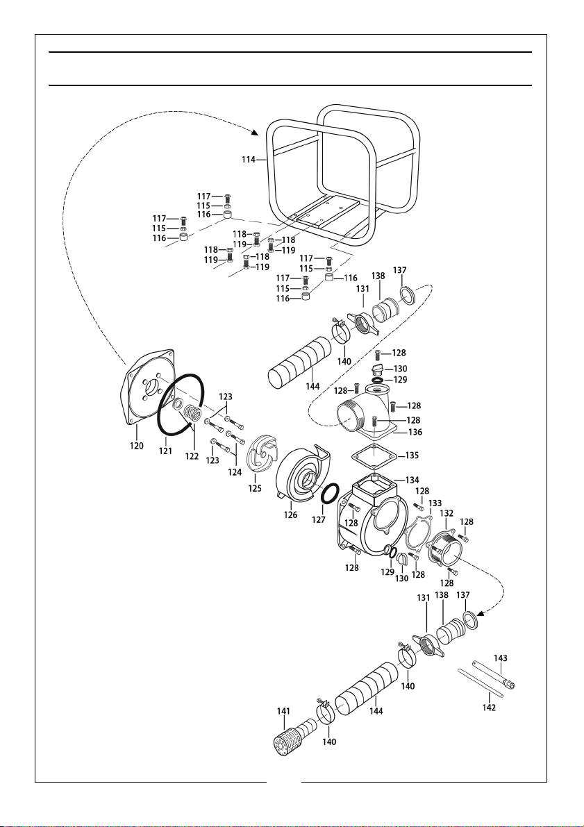
PUMP COMPONENTS DIAGRAM - PW3
17
Parts & Service: 020 8988 7400 / E-mail: [email protected] or [email protected]
Page 18
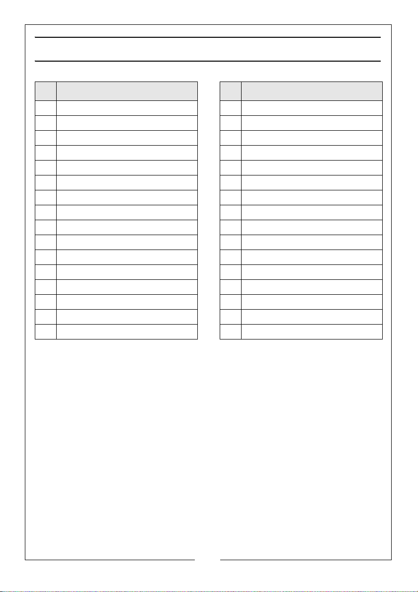
PUMP COMPONENTS LIST - PW3
NO Description NO Description
114 23” Frame sub-assembly 130 Drain Plug
115 Nut M6 131 3” Hose Union
116 Rubber Foot 132 3” Inlet Flange
117 Bolt M6 x 12 133 Gasket
118 Nut M8 134 Front Housing
119 Bolt M8 x 32 135 Gasket
120 Rear Housing 136 3” Outlet Flange
121 O-Ring 137 Gasket 3”
122 Mechanical Seal 138 Pipe 3”
123 Copper Washer 139 N/A
124 Allen Headed Bolt 140 Jubillee Clip
125 Impeller 141 Strainer
126 Impeller Cover 142 Extension Bar
127 O-Ring 143 Spark Plug Wrench (short)
128 Bolt 144 Water Hose (not supplied)
129 O-Ring
18
Parts & Service: 020 8988 7400 / E-mail: [email protected] or [email protected]
Page 19
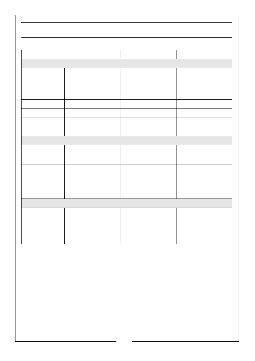
SPECIFICATIONS
Model PW2 PW3
Engine
Engine Model 168F-2A 168F-2A
Engine Type 4-stroke OHV single
Motor HP 6.5HP (4.0kw) 6.5HP (4.0kw)
Rotational velocity 3600 rpm 3600 rpm
Fuel tank Capacity 3.6L 3.6L
Oil Capacity 0.6L 0.6L
Performance Data
Outlet size 2” 3”
Max Water Flow
Max Head 26M 30M
Max Suction 7.5M 7.5M
Guaranteed sound
power
Dimensions
Length (mm) 500 525
Width (mm) 395 395
Height (mm) 380 440
Weight 27kg 29kg
cylinder with forced
air cooling
416 L/m (25m
107 LWA dB 109 LWA dB
3
4-stroke OHV single
cylinder with forced
air cooling
/h) 800 L/m (48m3/h)
19
Parts & Service: 020 8988 7400 / E-mail: [email protected] or [email protected]
Page 20
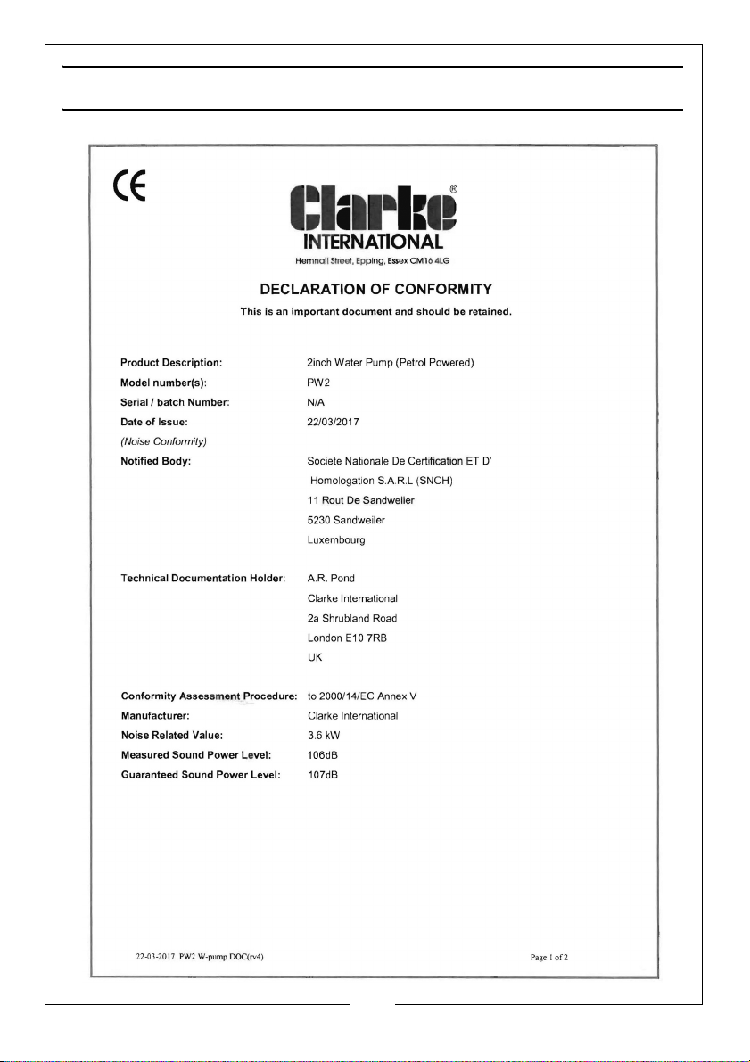
DECLARATION OF CONFORMITY - PW2
20
Parts & Service: 020 8988 7400 / E-mail: [email protected] or [email protected]
Page 21
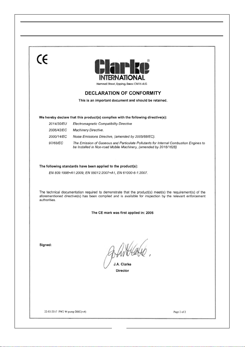
DECLARATION OF CONFORMITY - PW2
21
Parts & Service: 020 8988 7400 / E-mail: [email protected] or [email protected]
Page 22
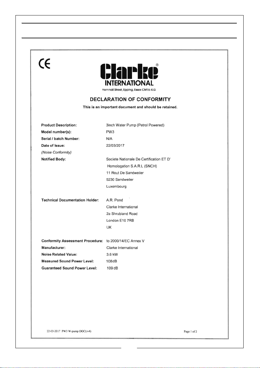
DECLARATION OF CONFORMITY - PW3
22
Parts & Service: 020 8988 7400 / E-mail: [email protected] or [email protected]
Page 23
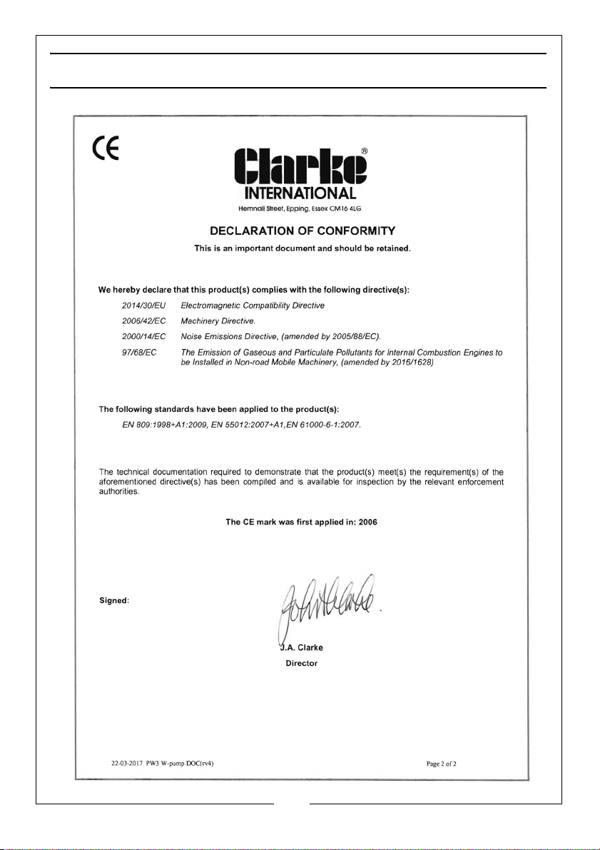
DECLARATION OF CONFORMITY - PW3
23
Parts & Service: 020 8988 7400 / E-mail: [email protected] or [email protected]
Page 24

 Loading...