

Page 1
THIS PRODUCT IS FOR
OUTDOOR USE ONLY
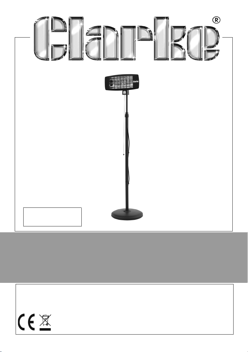
INFRARED QUARTZ HEATER
MODEL NO: IQ2000S
PART NO: 6939006
ASSEMBLY & OPERATION
INSTRUCTIONS
ORIGINAL INSTRUCTIONS
GC0620 - ISS 4
Page 2
INTRODUCTION
Thank you for purchasing this CLARKE Infrared Heater.
PLEASE NOTE THAT THIS PRODUCT IS FOR OUTDOOR USE ONLY
Before attempting to use this product, please read this manual thoroughly and
follow the instructions carefully. In doing so you will ensure the safety of yourself
and that of others around you, and you can look forward to your purchase
giving you long and satisfactory service.
OPERATING PARAMETERS
• It must be operated as prescribed in the operating manual.
• Is not intended to be used for domestic use or for the heating of
habitable areas.
• Is not intended to be used to reach and maintain a certain level of
human thermal comfort within an enclosed space in which the heater is
situated.
• Is not intended to be used in enclosed areas with restricted ventilation.
• Is not for use in areas with high levels of fluctuating drafts.
• Is not intended for warming animals or live stock.
GUARANTEE
This product is guaranteed against faulty manufacture for a period of 12
months from the date of purchase. Please keep your receipt which will be
required as proof of purchase.
This guarantee is invalid if the product is found to have been abused or
tampered with in any way, or not used for the purpose for which it was
intended.
Faulty goods should be returned to their place of purchase, no product can
be returned to us without prior permission.
This guarantee does not effect your statutory rights.
2
Parts & Service: 020 8988 7400 / E-mail: [email protected] or [email protected]
Page 3

SAFETY PRECAUTIONS
GENERAL
1. Always read and ensure you fully understand the following precautions
and the hazards associated with this type of heater. Do not allow anyone
who has not read these instructions to operate this heater. Please keep
these instructions in a safe place for future reference.
2. Always check for damage before using the heater. Any damage should
be properly repaired or the part replaced. If in doubt, DO NOT use the
heater and consult your local Clarke dealer.
3. Never carry out any modifications to this product. If experiencing difficulty
of any kind consult your local dealer.
4. Use the heater in accordance with any applicable fire regulations.
OPERATING ENVIRONMENT
1. Never use the heater where petrol, paint thinners or other highly flammable
vapour or where high levels of airborne dust may be present.
2. Disconnect the heater from the power supply when not in use.
3. Never place anything on top of the heater. so as to impede free air flow.
4. Do not expose the heater or power cable to rain or wet conditions. Any
water entering the heater will increase the risk of electric shock. The heater
must be protected from rain.
5.
ever locate the heater near combustible materials such as curtains,
N
furniture etc. Allow a distance of at least 1.5 metres.
Allow a distance of at least 1.5
6.
avoid installing the heater close to power socket outlets.
7. Do not allow the heating element to become covered with dust which
could become a fire hazard. If used in a dusty workplace it should be
cleaned as described under Cleaning and Maintenance.
8. Never touch the heater element for at least 15 minutes after switching off.
9. Do not leave the heater unattended.
10. Do not use this heater with a programmable timer used to switch it on
automatically.
11. Never attach any duct work to the front of the heater.
12. That this product is for outdoor use only.
metres from an adjacent wall and
3
Parts & Service: 020 8988 7400 / E-mail: [email protected] or [email protected]
Page 4
PERSONAL SAFETY
1. When the heater is to be operated in the presence of other people the
user is responsible for informing those present of the safety precautions and
of the hazards involved.
2. The heater is not to be used by children or persons with reduced physical,
sensory or mental capabilities, or lack of experience and knowledge.
3. Always ensure that people and animals are a safe distance from the front
of the heater when in operation.
4. This heater will be hot when in operation and should not be touched until it
has fully cooled down after switching off.
5. Never leave the heater plugged in without adult supervision if children or
animals are likely to be present.
ELECTRICAL SAFETY
1. Make sure that the voltage on the rating label is the same voltage as the
power supply. If in doubt consult a qualified electrician.
2. Never modify the plug in any way. Do not use adaptor plugs with earthed
appliances. Correct plugs and outlets will reduce the risk of electric shock.
3. Do not abuse the electrical cable. Keep the cable away from sources of
heat, sharp edges or moving parts. Damaged or tangled cables increase
the risk of electric shock.
4. Regularly inspect the power cable for damage. DO NOT use if damaged &
keep it away from the source of heat. If damaged, it must be replaced.
DAMAGE & REPAIRS
1. If necessary, have your heater repaired by a qualified person using
identical replacement parts to maintain the safety of the heater.
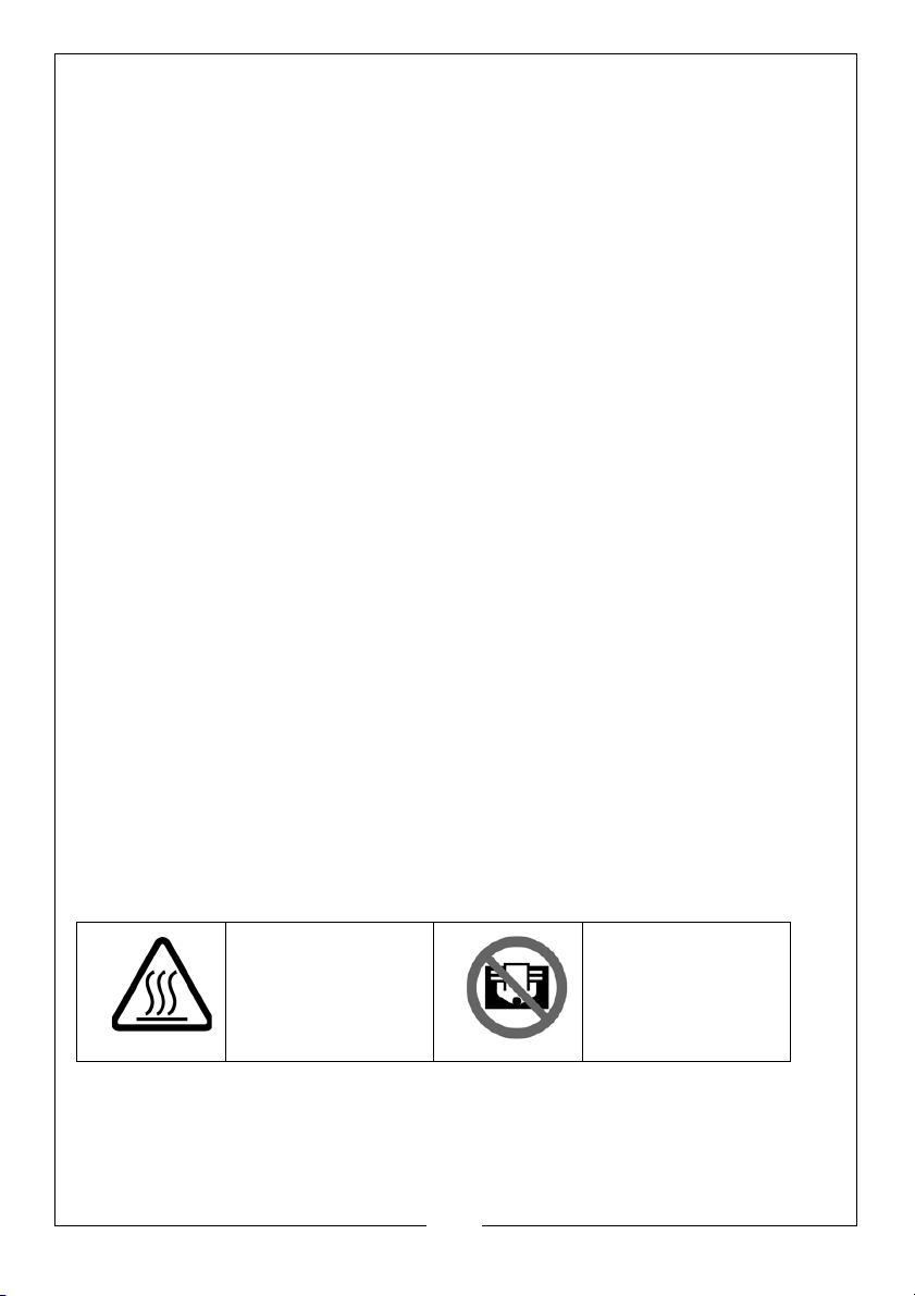
SAFETY SYMBOLS
Hot surface, do not
.
touch
The above symbols are found on the heater.
4
Parts & Service: 020 8988 7400 / E-mail: [email protected] or [email protected]
Do not cover.
Page 5
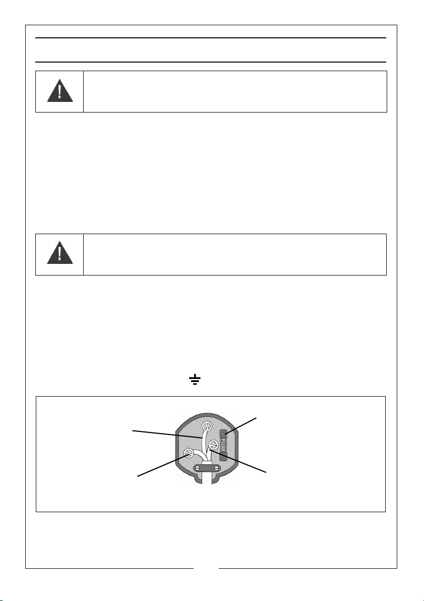
ELECTRICAL CONNECTIONS
Plug must be BS1363/A approved.
Always fit a 13 Amp fuse.
Ensure that the outer sheath of the cable is firmly held by the clamp
Neutral
(Blue)
Live
(Brown)
Earth
(Green and Yellow)
WARNING! READ THESE ELECTRICAL SAFETY INSTRUCTIONS
THOROUGHLY BEFORE CONNECTING THE PRODUCT TO THE
MAINS SUPPLY.
Before switching the product on, make sure that the voltage of your electricity supply is
the same as that indicated on the rating plate. This product is designed to operate on
230VAC 50Hz. Connecting it to any other power source may cause damage.
This product may be fitted with a non-rewireable plug. If it is necessary to change the
fuse in the plug, the fuse cover must be refitted. If the fuse cover becomes lost or
damaged, the plug must not be used until a suitable replacement is obtained.
If the plug has to be changed because it is not suitable for your socket, or due to
damage, it should be cut off and a replacement fitted, following the wiring instructions
shown below. The old plug must be disposed of safely, as insertion into a mains socket
could cause an electrical hazard
WARNING! THE WIRES IN THE POWER CABLE OF THIS PRODUCT
ARE COLOURED IN ACCORDANCE WITH THE FOLLOWING CODE:
BLUE = NEUTRAL BROWN = LIVE YELLOW AND GREEN = EARTH
If the colours of the wires in the power cable of this product do not correspond with the
markings on the terminals of your plug, proceed as follows.
• The wire which is coloured Blue must be connected to the terminal which is
marked N or coloured Black.
• The wire which is coloured Brown must be connected to the terminal which
is marked L or coloured Red.
• The wire which is coloured Yellow and Green must be connected to the
terminal which is marked E or or coloured Green.
.
.
We strongly recommend that this machine is connected to the mains supply
via a Residual Current Device (RCD)
If in any doubt, consult a qualified electrician. DO NOT attempt any repairs yourself.
Parts & Service: 020 8988 7400 / E-mail: [email protected] or [email protected]
5
Page 6
ASSEMBLY & OPERATION
Unpack the heater and check for any damage sustained in transit. Notify your
Clarke dealer immediately of any defects.
The heater is resistant to splashing but should be sheltered from direct rainfall,
as should the power cable, plug and supply outlet socket. A awning,
overhanging roof or other shelter should be used to protect from rain.
T
he heater should be positioned with at least 1.5 meters clearance from any
c
ombustible surfaces including furniture or other fabrics which could be
damaged by heat.
Ensure the heater faces the centre of
the space to be heated.
Never place any objects on, or
against the heater.
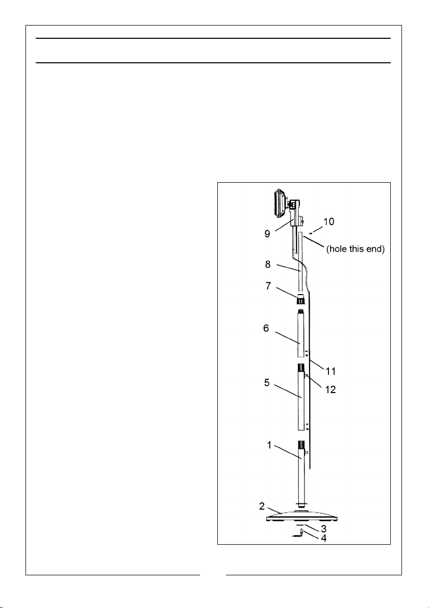
1. Set the lower tube (1) through the
hole in the base (2) with the
welded disc downwards & the
locating tongue in its seat in the
base. Secure with the washer (3)
and hand screw (4).
2. Connect tube (5) to the lower
tube (1) and secure with the two
screws.
3. Remove the screw (10) from the
end of the small tube (8) and
remove the locking ring (7) from
tube (6).
4. Slide the small tube (8) up through
the tube (6) (end with drilled hole
first), until it emerges from the
other end.
5. Screw the locking ring (7) back on
to tube 6.
6. Connect tube (6) to tube (5) and
secure with the two screws.
6
Parts & Service: 020 8988 7400 / E-mail: [email protected] or [email protected]
Page 7
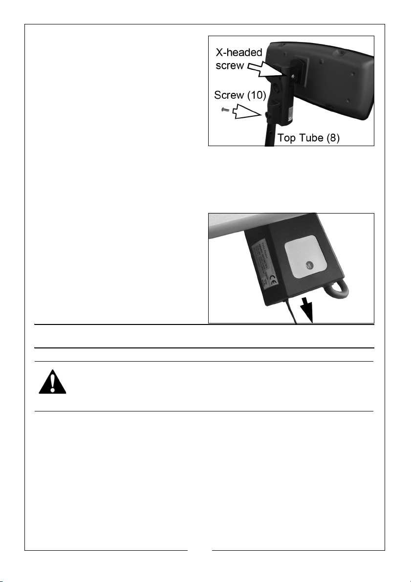
7. Fit the small tube (8) into the
socket in the control box (9) and
secure with the screw (10).
8. Clip the power cable (11) to the
clips (12).
9. Set the downwards angle of the
heater by loosening the mounting
bracket with a large x-head
screwdriver and adjusting the
angle before re-tightening.
10. Set the heater to the required height by loosening the locking ring (7) and
extending the top tube as required. Tighten the locking ring to secure.
Ensure all fittings are suitable secure before using the heater.
11. Connect the mains cable to a suitable power socket.
12. Pull the string repeatedly to cycle
through the following heat
settings;
• O = Off
• I = Low
• II = Medium
• III = High
CLEANING AND MAINTENANCE
WARNING: BEFORE CARRYING OUT ANY MAINTENANCE, ENSURE THE
HEATER IS SWITCHED OFF, IS DISCONNECTED FROM THE MAINS SUPPLY,
AND HAS BEEN GIVEN ADEQUATE TIME TO COOL DOWN.
PERIODICALLY
1. If there is any serious build up of dirt, wipe thoroughly with a damp cloth,
taking care that no moisture enters the heater.
2. Inspect the power cable for damage. Undue heat will cause the cable to
stiffen and crack in which case it should be replaced.
3. Ensure heating elements are free of dust (use compressed air to clean if
possible. (Always wear a dust mask if performing this task).
4. Refer to your Clarke dealer if the heater element needs replacing.
7
Parts & Service: 020 8988 7400 / E-mail: [email protected] or [email protected]
Page 8

FAULT FI N DI N G
SYMPTOM PROBLEM SOLUTION
Heater does
not
operate,
although
plugged in
and
switched on.
Plug is loose/ bad connection.
Fuse blown. Replace if necessary and investi-
No power at socket outlet. Insert plug into a suitable socket.
Input voltage incorrect. Ensure power supply matches the
Remove the plug & check the connection of the plug and socket.
gate the cause. If fuse blow
repeatedly, consult your Clarke
dealer.
rating on the label.
TECHNICAL SPECIFICATION
Dimensions (L x W x H) 175 x 480 x 270 (lamp unit) mm
Assembled height on stand 1575 (min) to 1900 (max) mm
Weight (including stand) 10.75 kg
Electrical Supply 230 V / 50hz
Power Cable length 1.8 m
Protection Degree IP24 (water splash)
Operating Temperature
Tilt Range Level to -25 degrees
Heat Output 2 kW
-20 to 30
°C
ENVIRONMENTAL RECYCLING POLICY
Through purchase of this product, the customer is taking on the
obligation to deal with the WEEE in accordance with the WEEE
regulations in relation to the treatment, recycling & recovery and
environmentally sound disposal of the WEEE.
In effect, this means that this product must not be disposed of with general
household waste. It must be disposed of according to the laws governing Waste
Electrical and Electronic Equipment (WEEE) at a recognised disposal facility.
8
Parts & Service: 020 8988 7400 / E-mail: [email protected] or [email protected]
Page 9
Page 10
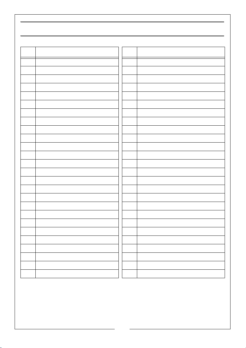
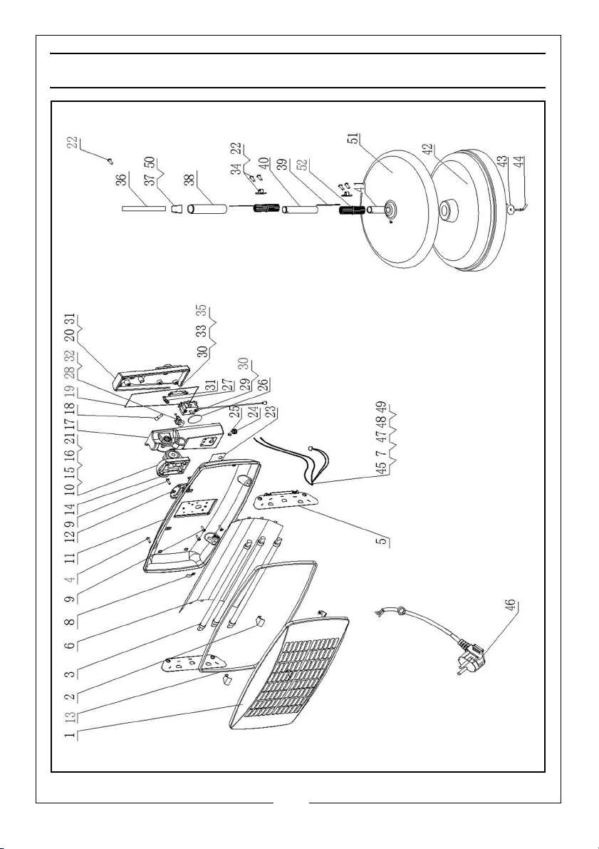
PARTS LIST
ID DESCRIPTION ID DESCRIPTION
1 Front Housing 27 Cable Clamp
2 Front Housing Clip 28 Screw
3 Heating Element 29 Switch
4 Self-tapping Screw 30 Self tapping Screw
5 Reflector Bracket 31 Self tapping Screw
6Reflector 32Screw
7 Nut 33 Switch Bracket
8 Cable Clip 34 Cable Clip
9 Self tapping Screw 35 Screw
10 Spring Washer 36 Straight Tube
11 Rear Housing 37 Inner Fastener
12 Hinge Board 38 Upper Tube
13 U-seal Ring 39 Screw Plate
14 Hinge Seal 40 Middle Tube
15 Hinge 41 Lower Tube
16 Screw 42 Main Base
17 Control Box Bottom 43 Large Washer
18 Closed End Connector 44 Hand Screw
19 Seal 45 Internal Wiring Assembly
20 Control Box Cover 46 Power Cable
21 Nut 47 Screw
22 Internal Wire Assembly 48 Spring Washer
23 PVC Sticker 49 Star Washer
24 Cable Bush 50 Outer Sleeve
25 Drawing Bush 51 Base Cover
26 Display Disc 52 Joint
10
Parts & Service: 020 8988 7400 / E-mail: [email protected] or [email protected]
Page 11
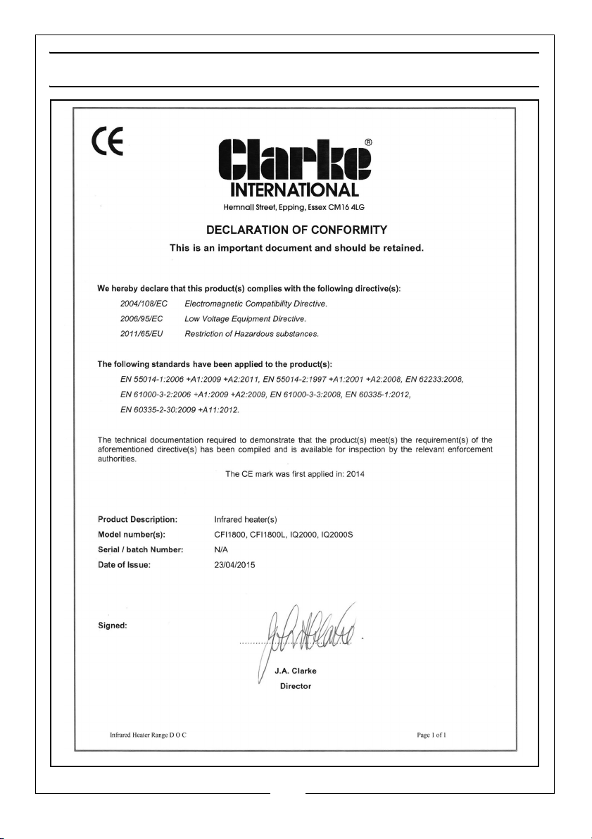
DECLARATION OF CONFORMITY
11
Parts & Service: 020 8988 7400 / E-mail: [email protected] or [email protected]
Page 12

 Loading...