

Page 1

BENCH GRINDER
MODEL NO: CBG6250
PART NO: 6500522
OPERATION & MAINTENANCE
INSTRUCTIONS
ORIGINAL INSTRUCTIONS
GC0321 - rev 5
Page 2

INTRODUCTION
Thank you for purchasing this CLARKE Bench Grinder.
Before attempting to use this product, please read this manual thoroughly and
follow the instructions carefully. In doing so you will ensure the safety of yourself
and that of others around you, and you can look forward to your purchase
giving you long and satisfactory service.
Please keep these instructions in a safe place for future reference.
SPECIFICATIONS
Model Number CBG6250
Part Number 6500522
Rated Voltage 230V~50Hz
Rated Input 150 W (S1)
No Load Speed 2980 RPM
Sound Pressure Level LpA 81 db
Sound Power Level LWA 90 db
Uncertainty Factor K 3
Weight 7.4 kg
Abrasive wheels supplied Coarse (36 Grit), Fine (60 Grit)
Wheel dimensions Dia (150mm) Thickness (20 mm) Bore (12.7 mm)
GUARANTEE
This product is guaranteed against faulty manufacture for a period of 12
months from the date of purchase. Please keep your receipt which will be
required as proof of purchase.
This guarantee is invalid if the product is found to have been abused or
tampered with in any way, or not used for the purpose for which it was
intended.
Faulty goods should be returned to their place of purchase, no product can
be returned to us without prior permission.
This guarantee does not effect your statutory rights.
2
Parts & Service: 020 8988 7400 / E-mail: [email protected] or [email protected]
Page 3

POWER TOOL SAFETY WARNINGS
1) WORK AREA
1. Keep the work area clean and well lit. Cluttered and dark areas invite
accidents.
2. Do not operate power tools in explosive atmospheres, such as in the
presence of flammable liquids, gases or dust. Power tools create sparks
which may ignite the dust or fumes.
3. Keep children and bystanders away while operating a power tool.
Distractions can cause you to lose control.
2) ELECTRICAL SAFETY
1. Power tool plugs must match the outlet. Never modify the plug in any way.
Do not use adapter plugs with earthed (grounded) power tools. Unmodified
plugs and matching outlets will reduce the risk of electric shock.
2. Do not expose power tools to rain or wet conditions. Water entering a
power tool will increase the risk of electric shock.
3. Do not abuse the cable. Never use it for carrying, pulling or unplugging the
power tool. Keep the cable away from heat, oil, sharp edges or moving
parts. Damaged or entangled cables increase the risk of electric shock.
4. When operating a power tool outdoors, use an extension cable suitable for
outdoor use. Use of a cable suitable for outdoor use reduces the risk of
electric shock
5. If operating the power tool in a damp location is unavoidable, use a
residual current device (RCD) protected supply.
3) PERSONAL SAFETY
1. Stay alert, watch what you are doing and use common sense when
operating a power tool. Do not use a power tool while you are tired or
under the influence of drugs, alcohol or medication. A moment of
inattention while operating power tools may result in personal injury.
2. Use safety equipment. Always wear eye protection. Safety equipment such
as dust mask, non-skid safety shoes, hard hat, or hearing protection used
for appropriate conditions will reduce personal injuries.
3. Avoid accidental starting. Ensure the switch is in the off position before
plugging in. Carrying power tools with your finger on the switch or plugging
in power tools that have the switch on invites accidents.
4. Remove any wrench before turning the power tool on. A wrench left
attached to a rotating part may result in personal injury.
3
Parts & Service: 020 8988 7400 / E-mail: [email protected] or [email protected]
Page 4

5. Do not overreach. Keep proper footing and balance at all times. This
enables better control of the power tool in unexpected situations.
6. Dress properly. Do not wear loose clothing or jewellery. Keep your hair,
clothing and gloves away from moving parts. Loose clothes, jewellery or
long hair can be caught in moving parts.
4) POWER TOOL USE AND CARE
1. Do not force the power tool. Use the correct accessories for your
application. The correct power tool will do the job better and safer at the
rate which it was designed.
2. Do not use the power tool if the switch does not turn it on and off. Any
power tool that cannot be controlled with the switch is dangerous and
must be repaired.
3. Disconnect the plug from the power source before changing accessories,
or storing power tools. Such preventive safety measures reduce the risk of
starting the power tool accidentally.
4. Store idle tools out of the reach of children and do not allow persons
unfamiliar with the power tool or these instructions to operate it. Power tools
are dangerous in the hands of untrained users.
5. Maintain power tools. Check for misalignment or binding of moving parts,
breakage of parts and any other condition that may affect the power
tool’s operation. If damaged, have the power tool repaired before use.
Many accidents are caused by poorly maintained power tools.
6. Use the power tool and accessories in accordance with these instructions
and in the manner intended, taking into account the working conditions
and the work to be performed. Use of the power tool for operations
different from intended could result in a hazardous situation.
7. The performance of this tool may vary, depending upon variations in line
voltage. Extension cable usage may also affect performance.
5) SERVICING
1. Have your power tool serviced by qualified service personnel using only
identical replacement parts. This will ensure that the safety of the power
tool is maintained.
6) BENCH GRINDER SPECIFIC SAFETY WARNINGS
1. Hold the hand tool or blade being sharpened firmly to prevent loss of
control.
2. NEVER install a abrasive flap wheel or sanding disc on this grinder.
3. Always replace a cracked grinding wheel immediately.
4. Never use damaged or incorrect grindstones. The stone and retaining bolt
were specially designed for your grinder, for optimum performance and
4
Parts & Service: 020 8988 7400 / E-mail: [email protected] or [email protected]
Page 5
safety of operation. Inspect the condition of the grinding stone before use
and do not use if any damage is noticed.
5. Do not use aluminium oxide wheels when grinding non-ferrous metals such
as aluminium or brass. Use silicon carbide wheels (not included) for grinding
non-ferrous metals.
6. Always use the tool rests to steady the workpiece. If the tool attachments
are not used, the torque of the spinning grinding/polishing wheel may pull
the workpiece from your hands.
7. Never leave the grinder unattended when it is connected to an electrical
power supply. Switch off the machine and unplug it before leaving.
8. ALWAYS check for damaged parts. Before further use of the tool, a guard
or other part that is damaged should be carefully checked to determine if
it would operate properly and perform its intended function. Check for
misalignment or binding of moving parts, breakage of parts and any other
condition that may affect the tool's operation. A part that is damaged
should be properly repaired or replaced at an authorised service Centre.
Following this rule will reduce the risk of electric shock, fire or serious injury.
9. Gloves, manufactured to the current European safety standards should be
worn when operating grinding equipment.
10. Eye protection manufactured to the current European safety standards
should be worn when operating grinding equipment.
NOTE: Bench grinders used in industrial environments may be subject to the
requirements of The Provision and Use of Work Equipment regulations
1992 (particularly regarding the training requirement of The Abrasive
Wheels Regulations 1970), or other legislation. If in doubt seek advice.
ENVIRONMENTAL RECYCLING POLICY
Through purchase of this product, the customer is taking on the
obligation to deal with the WEEE in accordance with the WEEE
regulations in relation to the treatment, recycling & recovery and
environmentally sound disposal of the WEEE.
In effect, this means that this product must not be disposed of with general
household waste. It must be disposed of according to the laws governing
Waste Electrical and Electronic Equipment (WEEE) at a recognised disposal
facility.
5
Parts & Service: 020 8988 7400 / E-mail: [email protected] or [email protected]
Page 6
SAFETY SYMBOLS
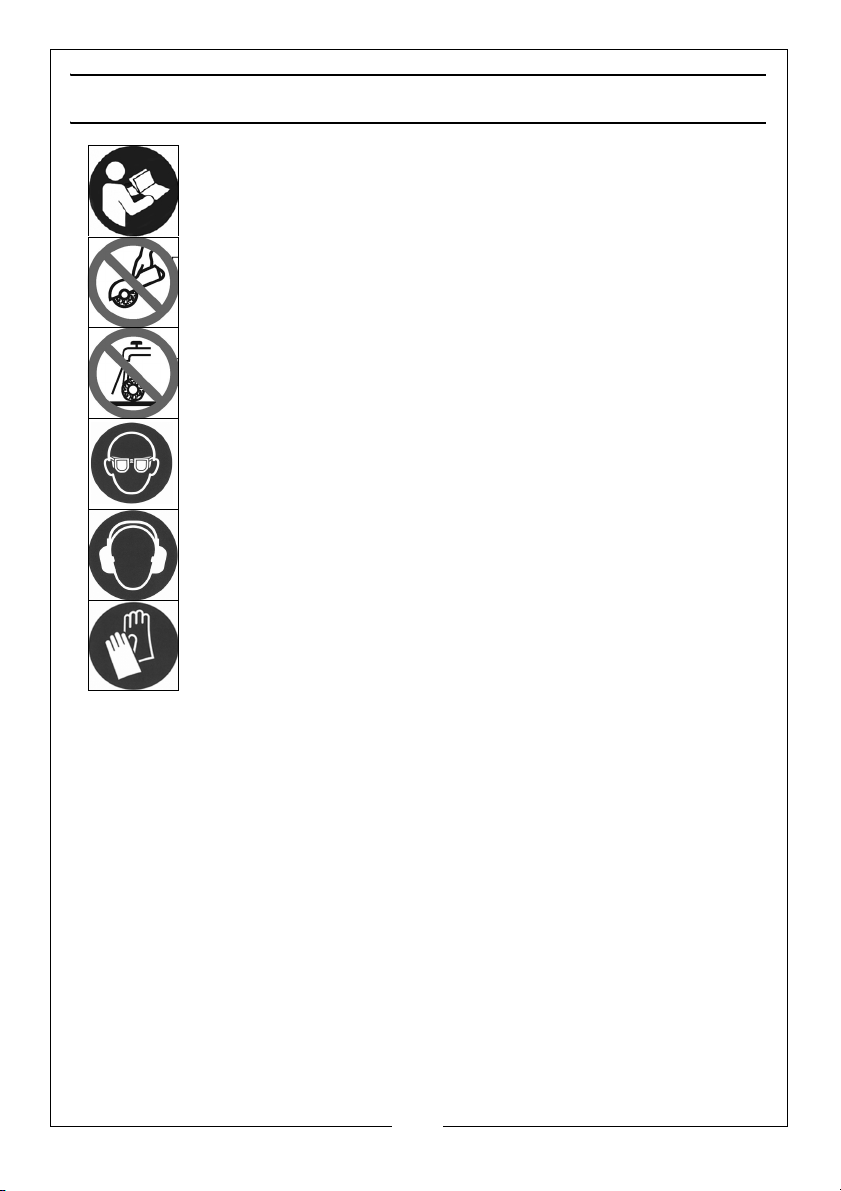
Read instruction manual before use
This machine is not suitable for hand held use
Not permitted for wet grinding
Wear eye protection
Wear ear defenders
Wear protective gloves
6
Parts & Service: 020 8988 7400 / E-mail: [email protected] or [email protected]
Page 7
ELECTRICAL CONNECTIONS
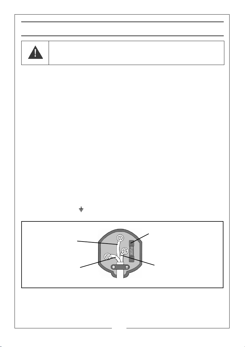
Plug must be BS1363/A approved.
Always fit a 5 Amp fuse.
Ensure that the outer sheath of the cable is firmly held by the clamp
Neutral
(Blue)
Live
(Brown)
Earth
(Green and Yellow)
WARNING: READ THESE ELECTRICAL SAFETY INSTRUCTIONS
THOROUGHLY BEFORE CONNECTING THE PRODUCT TO THE MAINS
SUPPLY.
Before switching the product on, make sure that the voltage of your electricity
supply is the same as that indicated on the rating plate. This product is
designed to operate on 230VAC 50Hz. Connecting it to any other power
source may cause damage.
This product may be fitted with a non-rewireable plug. If it is necessary to
change the fuse in the plug, the fuse cover must be refitted. If the fuse cover
becomes lost or damaged, the plug must not be used until a suitable
replacement is obtained.
If the plug has to be changed because it is not suitable for your socket, or due
to damage, it should be cut off and a replacement fitted, following the wiring
instructions shown below. The old plug must be disposed of safely, as insertion
into a mains socket could cause an electrical hazard.
If the colours of the wires in the power cable of this product do not correspond
with the markings on the terminals of your plug, proceed as follows.
•The Blue wire must be connected to the terminal which is marked N
or coloured Black.
•The Brown wire must be connected to the terminal which is marked L
or coloured Red.
•The Yellow and Green wire must be connected to the terminal which
is marked E or or coloured Green.
We strongly recommend that this machine is connected to the mains supply
via a Residual Current Device (RCD). If in any doubt, consult a qualified
electrician. DO NOT attempt any repairs yourself.
Parts & Service: 020 8988 7400 / E-mail: [email protected] or [email protected]
7
Page 8
CARTON CONTENTS
The following Items should be supplied in the carton, if any parts are missing or
damaged, please contact the clarke dealer where you purchased the bench
grinder.
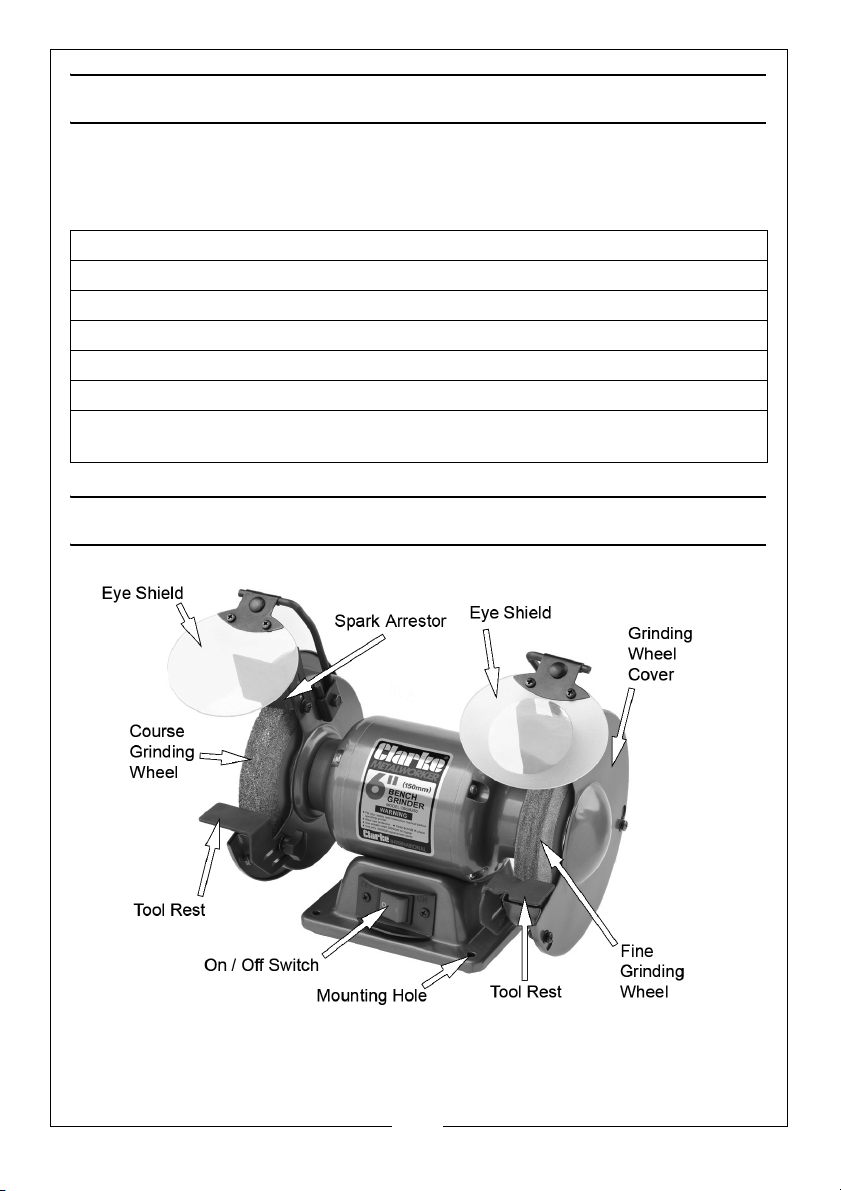
1 x Bench Grinder Assembly (2 grinding wheels attached)
2 x Eye Shields (1 with Built-in Magnifying Lens)
2 x Eye Shield Arms with bolts and washers
2 x Eye Shield Brackets
2 x Hand Knobs with washers
2 x Spark deflectors with screws and washers
2 x Tool Rests with screws and washers (1 flat and 1 with a channel for
sharpening drill bits)
PART IDENTIFICATION
8
Parts & Service: 020 8988 7400 / E-mail: [email protected] or [email protected]
Page 9
BEFORE USE
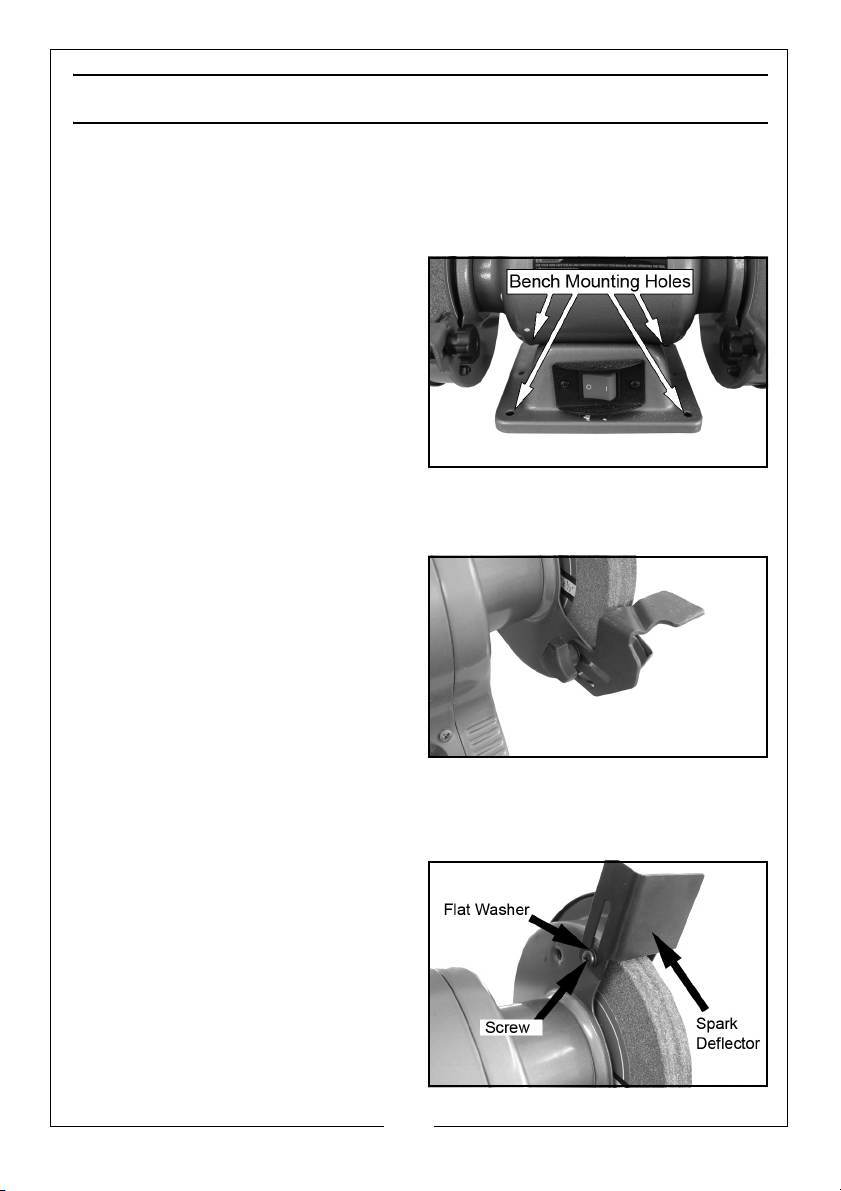
MOUNTING THE GRINDER ONTO A WORKBENCH
NOTE: We highly recommend that you bolt this bench grinder securely to a
workbench to gain maximum stability for your machine.
1. Using the base of the bench
grinder as a template, mark the
bench through the holes in the
casting.
2. Bolt the bench grinder on the
bench with bolts, washers and nuts
(not supplied).
3. To reduce vibration, mount the
bench grinder on a vibration
absorbing mat.
INSTALLING THE TOOL RESTS
1. Fix the tool rests to the bench
grinder with the screw and hand
knob as shown.
• The tool rests are adjustable
and should be positioned 1.5
mm from the grinding wheels.
• Ensure that the tool rest is firmly
fixed and horizontal.
• One of the tool rest has a
angled grove to allow you to sharpen the ends of drill bits.
INSTALLING THE SPARK DEFLECTORS
Fit both the spark deflectors to the
wheel guards using the screws
provided.
• Adjust the spark deflector
frequently to compensate for
wear of the wheel, keep the
distance between the spark
deflector and wheel as small as
possible and never more than
2mm.
9
Parts & Service: 020 8988 7400 / E-mail: [email protected] or [email protected]
Page 10
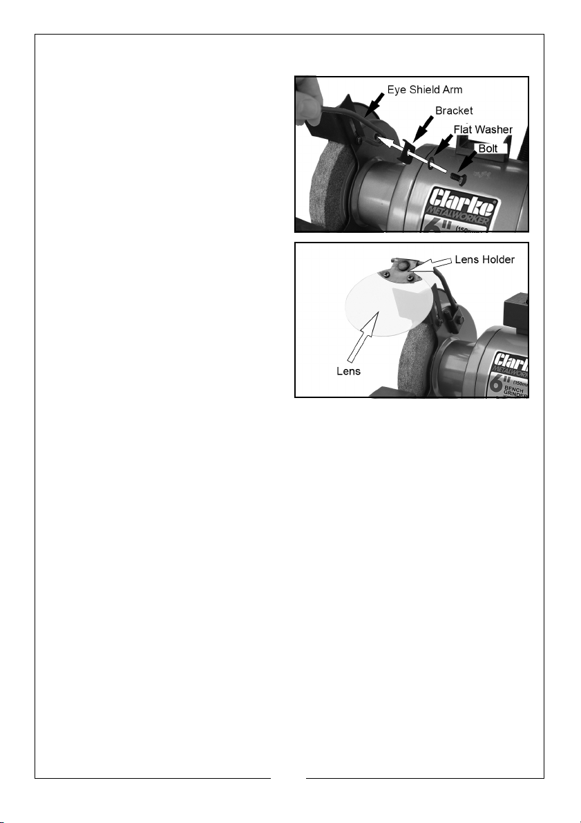
INSTALLING THE EYE SHIELDS
1. Attach the left eye shield arm to
the bench grinder using the
bracket, flat washer and bolt
supplied.
2. Fit the lens to the lens holder as
shown.
3. Repeat for right side eye shield.
NOTE: Adjust the eye shields to an
appropriate distance from the
tool rests avoiding
interference during operation.
SHARPENING TIPS
SCISSORS
If possible, take the scissors apart to make the sharpening operation easier
and safer. Remove material only from the outside surface and work from the
heavy end of the blade toward the tip.
KNIVES
Remove metal from both faces of most knives, working from the heavy end of
the blade toward the tip.
10
Parts & Service: 020 8988 7400 / E-mail: [email protected] or [email protected]
Page 11

OPERATION
CAUTION: KEEP ALL BYSTANDERS A SAFE DISTANCE AWAY FROM THE
TOOL AND NOT IN DIRECT LINE, FRONT OR BACK OF THE GRINDER.
CAUTION: ALWAYS WEAR SAFETY GLASSES
NOTE: Check that there is a 1.5 mm clearance between the tool rests and the
surface of the grinding wheel. Adjust as necessary.
NOTE: Check the gap between the spark deflectors and the surface of the
grinding wheel. These should also be a maximum of 2 mm. Adjust as
necessary.
NOTE: Check that the eyeshields have been secured in the correct position
and that the grinding wheel lock nuts are tight.
1. Stand to the side of the bench grinder and switch it on using the on/off
switch.
• Let the wheels reach full speed before use.
• The wheel rotates in the same direction as the arrow stamped in the
side of the wheel guard.
2. Hold the work piece firmly against the tool rest. Hold very small pieces with
pliers or other suitable clamps.
3. Feed the work piece smoothly and evenly against the grinding wheel.
4. Always keep the work piece moving across the face of the wheel. Grinding
against the same part of the wheel will cause uneven wear of the wheel
face.
• Grind only on the face of the grinding wheel and never the side of it.
NOTE: Prolonged grinding will cause most tools to become hot. Use care
when handling hot tools.
5. Switch the bench grinder off using the on/off switch when you have
finished.
DRESSING THE GRINDING WHEEL
The grinding wheel may need dressing occasionally. Only dress the wheel with
a proper dressing tool, whilst wearing safety goggles or glasses. If in doubt seek
professional advice. Dressing tools are available from your Clarke Dealer.
11
Parts & Service: 020 8988 7400 / E-mail: [email protected] or [email protected]
Page 12
MAINTENANCE
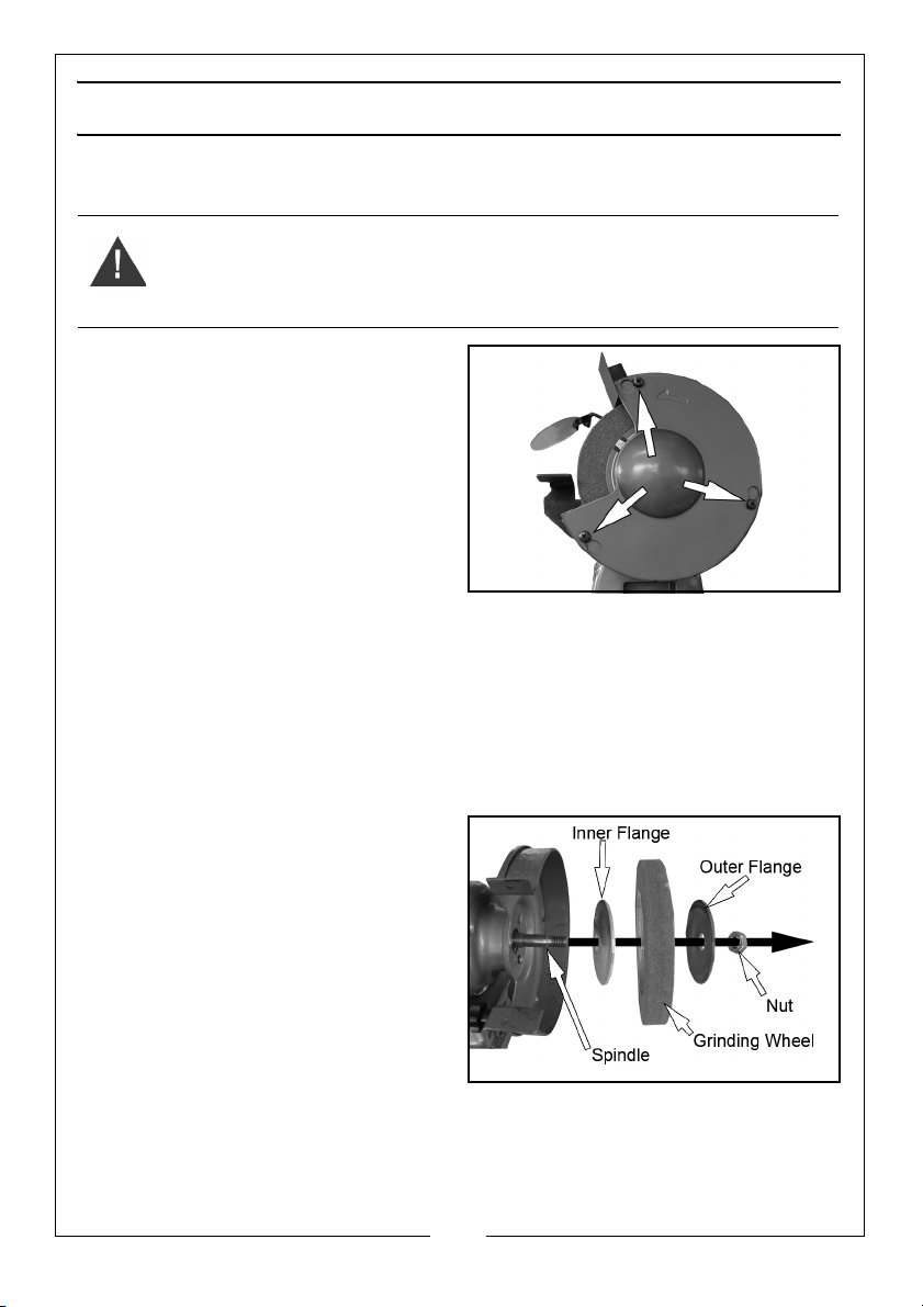
REPLACING THE GRINDING WHEELS
WARNING: DO NOT USE DAMAGED GRINDING WHEELS.
WARNING: SWITCH THE GRINDER OFF AND DISCONNECT THE POWER
SUPPLY BEFORE CHANGING THE GRINDING WHEELS
1. Loosen the screws shown and
rotate and remove the cover.
2. Hold the other wheel by hand, and
remove the nut and outer flange.
NOTE: The left hand grinding wheel
locking nut has a left handed
thread.
3. Slide off the old wheel and replace
with a new one.
• Use only wheels recommended by the manufacturer which have a
marked speed equal to or greater than the speed marked on the
nameplate of the tool.
• The disc should have maximum dimensions of 150 mm diameter, 20
mm thick with a bore size of 12.7 mm.
• Inspect the wheel for cracks, chips or any other visible damage,
damaged abrasive products must be destroyed and discarded.
4. Replace the outer flange.
• Make sure both wheel flanges
are placed with the concave
sides towards the wheel.
5. Replace the nut securely.
• Do not overtighten as this may
damage the grinding wheel.
6. Re-assemble the guards fully prior
to carrying out testing.
• Each time after mounting, the wheel should be test run for a
reasonable time (approximately 1 minute).
12
Parts & Service: 020 8988 7400 / E-mail: [email protected] or [email protected]
Page 13
Page 14

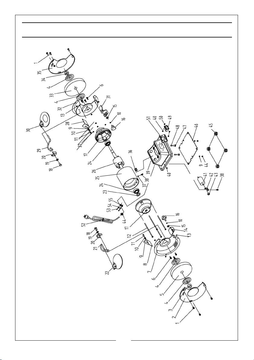
PART LIST
1 Philips Screw
2Left Guard Cover
3 I Type Hex Nut
4 Wheel Flange
5 Wheel (36#)
6 Philips Screw
7Left Guard Inner Cover
8Left Spark Deflector
9 Flat Washer
10 Standard Washer
11 Philips Screw
12 Philips Screw (tie rod)
13 Lock Nut
14 Left Work Rest
15 Big Flat Washer
16 Lock Knob
17 End Cap
18 Nut
19 Flat Washer
20 Bracket
21 Left Eyeshield Mounting Rod
22 Flat Eyeshield Assembly
23 Wavy Washer
24 Bearing
25 Stator
26 Rotor
27 Nut
28 Right Spark Deflector
29 Right Guard Mounting Rod
30 Magnifier Eyeshield Assembly
31 Right Work Rest
32 Right Guard Inner Cover
33 Wheel (60#)
34 I type Hex Nut
35 Right Guard Cover
36 Wire Bushing
37 Lock Washer
38 Philips Screw
39 Base
40 Nut
41 Capacitor
42 Capacitor Bracket
43 Nut
44 Strain Relief
45 Rubber Foot
46 Bottom Cover
47 Philips Screw
48 Standard Washer
49 Switch
50 Philips Screw
51 Switch Plate
52 Power Cable & Plug
53 Philips Screw
54 Cable Clamp Base Plate
55 Cable Clamp
14
Parts & Service: 020 8988 7400 / E-mail: [email protected] or [email protected]
Page 15
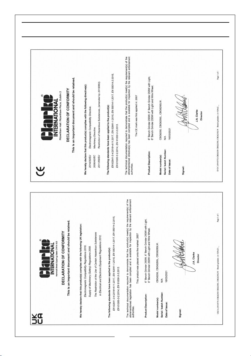
DECLARATION OF CONFORMITY
15
Parts & Service: 020 8988 7400 / E-mail: [email protected] or [email protected]
Page 16

 Loading...