

Page 1

OSCILLATING BELT/BOBBIN SANDER
MODEL NO: COEBS1
PART NO: 6500460
OPERATION & MAINTENANCE
INSTRUCTIONS
LS0620 - ISS 2ORIGINAL INSTRUCTIONS
Page 2
INTRODUCTION
Thank you for purchasing this CLARKE product.
Before attempting to use this product, please read this manual thoroughly and
follow the instructions carefully. In doing so you will ensure the safety of yourself
and that of others around you, and you can look forward to your purchase
giving you long and satisfactory service.
GUARANTEE
This product is guaranteed against faulty manufacture for a period of 12
months from the date of purchase. Please keep your receipt which will be
required as proof of purchase.
This guarantee is invalid if the product is found to have been abused or
tampered with in any way, or not used for the purpose for which it was
intended.
Faulty goods should be returned to their place of purchase, no product can
be returned to us without prior permission.
This guarantee does not effect your statutory rights.
ENVIRONMENTAL RECYCLING POLICY
Through purchase of this product, the customer is taking on the
obligation to deal with the WEEE in accordance with the WEEE
regulations in relation to the treatment, recycling & recovery and
environmentally sound disposal of the WEEE.
In effect, this means that this product must not be disposed of with general
household waste. It must be disposed of according to the laws governing
Waste Electrical and Electronic Equipment (WEEE) at a recognised disposal
facility.
2
Parts & Service: 020 8988 7400 / E-mail: [email protected] or [email protected]
Page 3

GENERAL SAFETY RULES
WARNING: READ ALL
INSTRUCTIONS. FAILURE TO
FOLLOW ALL INSTRUCTIONS
LISTED BELOW MAY RESULT IN
ELECTRIC SHOCK, FIRE AND/OR
SERIOUS INJURY.
1. Keep work area clear
• Cluttered areas and benches
invite injuries.
2. Consider work area environment
• Do not expose tools to rain.
• Do not use tools in damp or wet
locations.
• Keep work area well lit.
• Do not use tools in the presence
of flammable liquids or gases.
3. Guard against electric shock
• Avoid body contact with earthed
or grounded surfaces (e.g. pipes,
radiators, ranges, refrigerators).
4. Keep other persons away
• Do not let persons, especially
children, not involved in the work
touch the tool or the extension
cord and keep them away from
the work area.
5. Store idle tools
• When not in use, tools should be
stored in a dry locked-up place,
out of reach of children.
6. Use protective equipment
• Use safety glasses.
• Use face or dust mask if working
operations create dust.
7. Do not force the tool
• It will do the job better and safer
at the rate for which it was
intended.
8. Use the right tool
• Do not force small tools to do the
job of a heavy duty tool.
• Do not use tools for purposes not
intended; for example do not use
circular saws to cut tree limbs or
logs.
9. Dress properly
• Do not wear loose clothing or
jewellery, they can be caught in
moving parts.
• Non-skid footwear is
recommended when working
outdoors.
• Wear protective hair covering to
contain long hair.
10. Dust extraction equipment
• Ensure dust extraction equipment
is used.
11. Do not abuse the cord
• Never yank the cord to
disconnect it from the socket.
Keep the cord away from heat,
oil and sharp edges.
12. Secure the work
• Where possible use clamps or a
vice to hold the work. It is safer
than using your hand.
13. Do not overreach
• Keep proper footing and
balance at all times.
3
Parts & Service: 020 8988 7400 / E-mail: [email protected] or [email protected]
Page 4

14. Maintain tools with care
•.
• Inspect tool cords periodically
and if damaged have them
repaired by an authorized
service facility.
• Inspect extension cords
periodically and replace if
damaged.
• Keep handles dry, clean and
free from oil and grease.
15. Disconnect tools
• When not in use, before servicing
and when changing accessories
such as blades, bits and cutters,
disconnect tools from the power
supply.
16. Remove adjusting keys and
wrenches
• Form the habit of checking to
see that keys and adjusting
wrenches are removed from the
tool before turning it on.
17. Avoid unintentional starting
• Ensure switch is in “off' position
when plugging in.
18. Use outdoor extension leads
• When the tool is used outdoors,
use only extension cords
intended for outdoor use and so
marked.
19. Stay alert
• Watch what you are doing, use
common sense and do not
operate the tool when you are
tired.
20. Check damaged parts
• Before further use of tool, it
should be carefully checked to
determine that it will operate
properly and perform its
intended function.
• Check for alignment of moving
parts, binding of moving parts,
breakage of parts, mounting
and any other conditions that
may affect its operation.
• A guard or other part that is
damaged should be properly
repaired or replaced by an
authorized service centre unless
otherwise indicated in this
instruction manual.
• Have defective switches
replaced by an authorized
service centre.
• Do not use the tool if the switch
does not turn it on and off.
21. Warning
• The use of any accessory or
attachment other than those
recommended in this instruction
manual may present a risk of
personal injury.
22. Have your tool repaired by a
qualified person
• This electric tool complies with
the relevant safety rules. Repairs
should only be carried out by
qualified persons using original
spare parts, otherwise this may
result in considerable danger to
the user.
4
Parts & Service: 020 8988 7400 / E-mail: [email protected] or [email protected]
Page 5

SANDER SPECIFIC RULES
• FIRMLY CLAMP OR BOLT your
sander to a workbench or table
at approximately hip height.
• NEVER stand or have any part of
your body in line with the path of
the workpiece.
• PLAN YOUR WORK TO REDUCE
THE RISK OF THROWBACKS (when
the workpiece catches the
sanding drum and is torn from
your hands).
• MAKE SURE THERE IS NO DEBRIS
between the workpiece and its
supports.
• WHEN SANDING IRREGULARLY
SHAPED WORKPIECES, plan your
work support so it will not slip and
be pulled from your hands.
• USE EXTRA CAUTION WITH LARGE,
very small or awkward
workpieces.
• NEVER USE THIS SANDER to finish
pieces too small to hold by hand.
• USE EXTRA SUPPORTS (TABLES,
SAW HORSES, BLOCKS, ETC.) for
any workpieces large enough to
tip when not secured to the work
surface.
•NEVER sand more than one
piece at a time. DO NOT STACK
more than one workpiece on the
sander table at a time.
• ALWAYS FEED WORKPIECE FROM
LEFT TO RIGHT against the
direction the drum sleeve is
rotating.
• DO NOT USE DRUMS, sanding
sleeves or belts which show visual
signs of wear such as grooves,
tears or rips.
• ALWAY S S TAY A LE R T! Do n ot al l ow
familiarity (gained from frequent
use of your sander) to cause a
careless mistake. ALWAYS
REMEMBER that a careless
fraction of a second is sufficient
to inflict severe injury.
• MAKE SURE THE WORK AREA HAS
AMPLE LIGHTING to see the work
and that no obstructions will
interfere with safe operation
BEFORE performing any work
using your sander.
• ALWAYS TURN OFF THE SANDER
before disconnecting it to avoid
accidental starting when
reconnecting to power supply.
• NEVER leave the sander
unattended while connected to
a power source.
• SUPPORT WORKPIECE with mitre
gauge, work rest, or worktable.
• SAVE THESE INSTRUCTIONS. Refer
to them frequently and use them
to instruct others who may use
this sander. If you loan someone
this sander, loan them these
instructions also.
5
Parts & Service: 020 8988 7400 / E-mail: [email protected] or [email protected]
Page 6
SANDING DUST SAFETY WARNINGS
Some dust created by sanding, and other construction activities contains
chemicals known to cause cancer, birth defects or other reproductive harm.
Some examples of these chemicals are:
•lead from lead-based paints,
• crystalline silica from bricks and cement and other masonry products, and
• arsenic and chromium from chemically-treated lumber.
Your risk from these exposures varies, depending on how often you do this type
of work. To reduce your exposure to these chemicals: work in a well ventilated
area, and work with approved safety equipment, such as those dust masks that
are specially designed to filter out microscopic particles.
SAFETY SYMBOLS
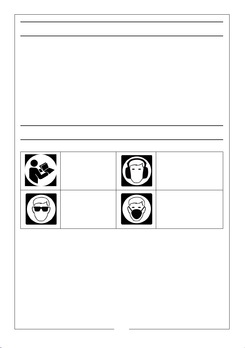
Read this instruction
booklet carefully.
Wear eye
protection.
Wear ear protection.
Wear a dust mask that is
specially designed to
filter microscopic
particles.
6
Parts & Service: 020 8988 7400 / E-mail: [email protected] or [email protected]
Page 7
ELECTRICAL CONNECTIONS
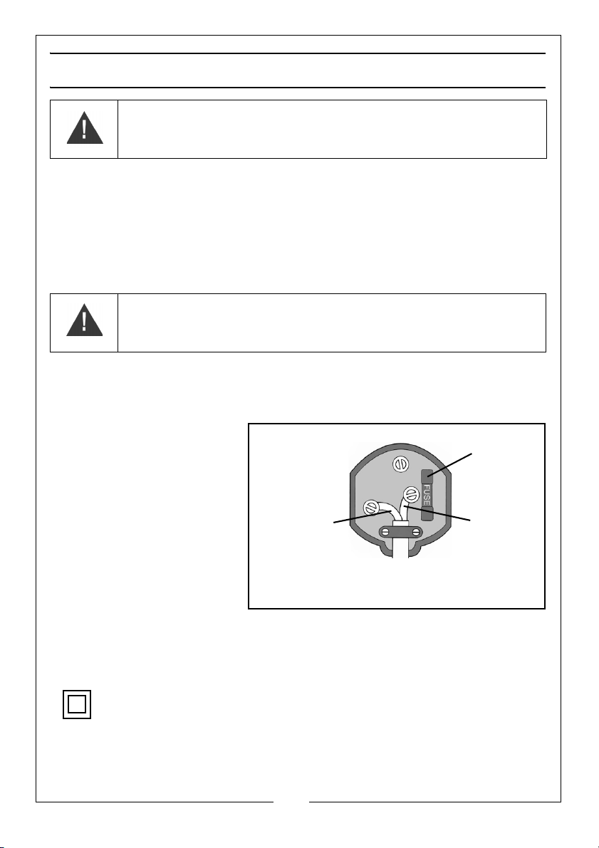
Plug must be BS1363/A approved.
Always fit
Ensure that the outer sheath of
Neutral
(Blue)
Live
(Brown)
a 5 Amp
the cable is firmly held by the clamp
fuse.
WARNING: READ THESE ELECTRICAL SAFETY INSTRUCTIONS
THOROUGHLY BEFORE CONNECTING THE PRODUCT TO THE MAINS
SUPPLY.
Connect the mains lead to a standard, 230 Volt (50Hz) electrical supply
through an approved 13 amp BS 1363 plug, or a suitably fused isolator switch.
If the plug has to be changed because it is not suitable for your socket, or
because of damage, it must be removed and a replacement fitted, following
the wiring instructions shown below. The old plug must be discarded safely, as
insertion into a power socket could cause an electrical hazard
WARNING: THE WIRES IN THE POWER CABLE OF THIS PRODUCT ARE
COLOURED IN ACCORDANCE WITH THE FOLLOWING CODE:
BLUE = NEUTRAL BROWN = LIVE
If the colours of the wires in the power cable do not agree with the markings
on the plug.
• The BLUE wire must be
connected to the
terminal which is
marked N or coloured
black.
• The BROWN wire must
be connected to the
terminal which is
marked L or coloured
red.
.
AN APPROVED RESIDUAL CURRENT DEVICE (RCD) WHICH HAS A TRIPPING
CURRENT OF LESS THAN 30mA MUST BE USED.
If you are not sure, consult a qualified electrician. DO NOT try to do any repairs
This symbol indicates that this is a Class II product, and does not require
an earth connection.
Parts & Service: 020 8988 7400 / E-mail: [email protected] or [email protected]
7
Page 8
CONTENTS
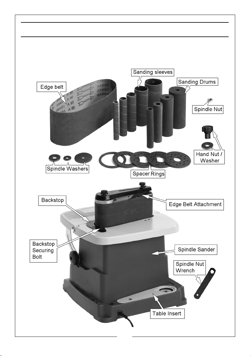
The following items should be supplied in the carton. If any parts are missing,
do not operate until the missing parts are replaced. Failure to follow this
instruction could result in serious injury.
8
Parts & Service: 020 8988 7400 / E-mail: [email protected] or [email protected]
Page 9
ASSEMBLY
SECURING THE SANDER TO A WORKBENCH
If sander is to be used in a permanent location, it should be fastened securely
to a workbench via the four securing holes (one on each corner).
1. Mark out the position of the holes.
2. Secure using suitable bolts, washers, and nuts (not supplied).
An alternative method is to fasten the sander to a mounting board.
The board should be sufficient size to avoid tipping while in use. Any good
grade of 3/4" plywood or chipboard will be sufficient.
The mounting board can then be clamped to a workbench when required.
DUST EXTRACTION
WARNING: CONTACT WITH, OR INHALATION OF DUST FROM LEAD BASED
PAINTS CAN ENDANGER THE HEALTH OF THE OPERATOR AND
BYSTANDERS. ALWAYS WEAR A SUITABLE DUST MASK WHEN USING THE
SANDER.
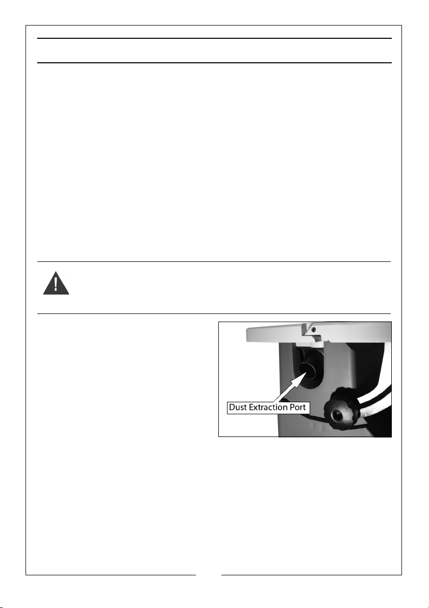
1. Connect a suitable dust collector
to the dust extraction port.
• The dust exhaust port has an
in ternal d iame t er of 3 6 mm an d
an outside diameter of 39 mm.
NOTE: Even with a dust collection
system, it is necessary to
periodically clean sanding
dust from the recess in the
table. A build up of dust in the
table recess may prevent the belt or spindle from making a complete
oscillation.
9
Parts & Service: 020 8988 7400 / E-mail: [email protected] or [email protected]
Page 10
EDGE SANDING SETUP
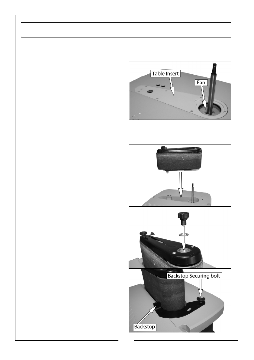
INSTALL THE SANDING BELT ASSEMBLY
1. If fitted, remove the fan and table
insert from the sander.
• Clear the recess of any debris.
2. Slide the fan onto the motor shaft
(vanes face down).
• You may need to rotate the fan
to get it to locate properly,
(when correctly fitted the fan
rotates with the spindle).
• The fan must be used at all times.
3. Slide sanding belt assembly over
the spindle as shown.
4. Fit the washer and hand nut.
• Do not overtighten the hand
nut.
5. Install the sanding belt (See
“Removing/installing the Sanding
Belt” on page 11.
6. Place the backstop into position
and secure in place with the
backstop securing bolt.
10
Parts & Service: 020 8988 7400 / E-mail: [email protected] or [email protected]
Page 11
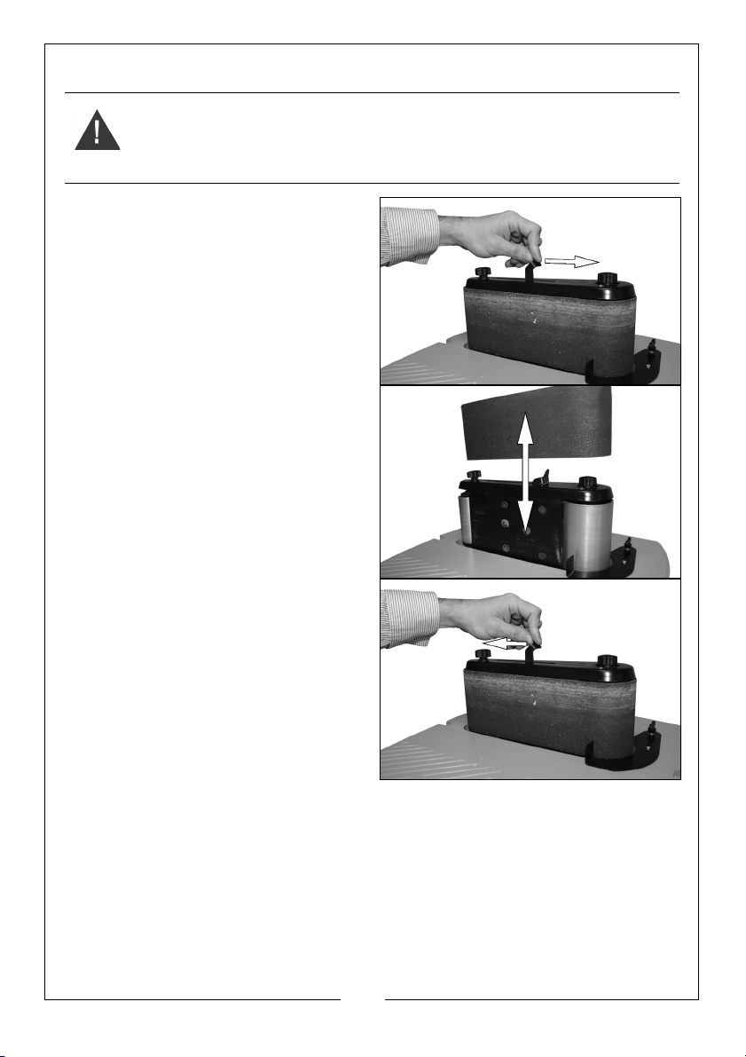
REMOVING/INSTALLING THE SANDING BELT
WARNING: MAKE SURE THAT THE TOOL IS UNPLUGGED BEFORE
INSTALLING/REMOVING THE SANDING BELT.
1. Move the belt tension lever fully to
the right as shown.
2. Slide the belt over the rollers and
centralise the belt.
• The arrows on the sanding belt
and machine should be
pointing in the same direction.
3. Move the belt tensioning lever to
the left.
• Keep the belt tensioning lever
under control at all times, do
not allow it to spring back.
• Make sure the belt tracks
correctly before use, See
“Sanding Belt Tracking” on
page 12.
11
Parts & Service: 020 8988 7400 / E-mail: [email protected] or [email protected]
Page 12
SANDING BELT TRACKING
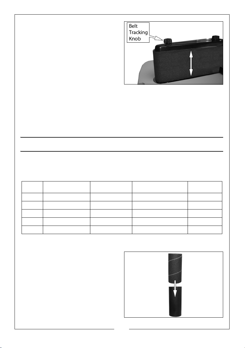
1. Plug in the power cable. Turn the
switch ON and immediately turn
the switch OFF again. Note if the
belt tends to slide off the drums.
• If it did not tend to slide off, it is
tracking properly.
• If the sanding belt runs down
(towards the table), turn the
tracking knob clockwise 1/4 turn.
• If the sanding belt runs up (away from the table), turn the tracking
knob counterclockwise 1/4 turn.
2. Turn the switch ON and immediately OFF again, noting belt movement.
Readjust the tracking knob if necessary.
BOBBIN SANDING SETUP
SELECTION OF SPACER RING INSERTS AND SPINDLE WASHERS
You must use the correct spacer ring and washers when fitting the bobbins
Bobbin
1½" 1½" 1½" 1½"
What Sanding Sleeve
Size
should you use
½" ½"
What drum should
you use
None
What spacer ring should
you use (inside diameter)
¾" ¾" ¾" ¾"
1" 1" 1" 1"
2" 2" 2" 2"
½"
What washer
should you use
Small
Small
Medium
Medium
Large
ASSEMBLING THE BOBBIN
Slide the sanding sleeve over the
drum as shown.
• If the sanding sleeve is difficult
to slide over the drum, apply
talcum powder to the outside
surface of the drum.
• The smallest sanding sleeve
slides directly onto the spindle
shaft and does not require a
drum.
12
Parts & Service: 020 8988 7400 / E-mail: [email protected] or [email protected]
Page 13
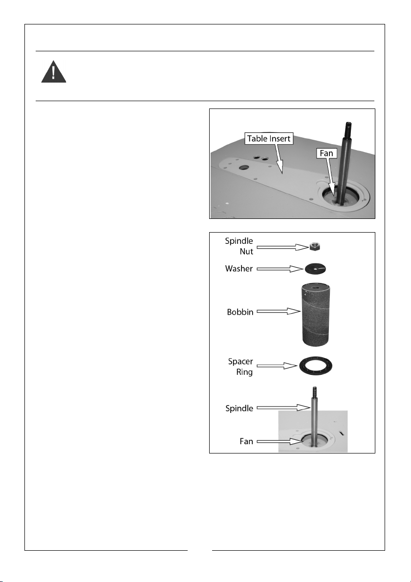
FITTING THE BOBBIN TO THE SANDER
WARNING: TO REDUCE THE RISK OF INJURY FROM ACCIDENTAL STARTING,
MAKE SURE THE SANDER IS UNPLUGGED BEFORE REMOVING OR
REPLACING THE SPACER RING INSERTS, SLEEVES AND DRUMS.
1. If fitted, remove the fan and table
insert from the sander.
2. Clear the recess of any debris.
3. Slide the fan back on to the
spindle (vanes face down) and
engaged fully.
• The fan must be used at all
times.
4. Replace the table insert.
5. Slide the bobbin onto the spindle.
NOTE: The smallest sanding sleeve
slides directly onto the spindle
shaft and not onto a drum.
6. Position the spacer ring in the
recess on the table insert.
• Use the smallest spacer ring
insert that will fit over the drum.
7. Install the correct washer.
• Use the largest washer that
does not overhang the sanding
sleeve.
8. Secure everything in place with
the spindle nut.
• A spindle nut wrench is
supplied.
NOTE: As you tighten the spindle nut,
the drum expands outwards
slightly to hold the sanding sleeve secure.
13
Parts & Service: 020 8988 7400 / E-mail: [email protected] or [email protected]
Page 14
USING THE SANDER
CAUTION: BEFORE TURNING THE SWITCH ON, MAKE SURE THE BELT OR
DRUM AND SLEEVE ARE PROPERLY INSTALLED.
WARNING: ALWAYS WEAR SAFETY GOGGLES OR SAFETY GLASSES WITH
SIDE SHIELDS WHEN OPERATING POWER TOOLS. FAILURE TO DO SO
COULD RESULT IN OBJECTS BEING THROWN INTO YOUR EYES, RESULTING
IN POSSIBLE SERIOUS INJURY.
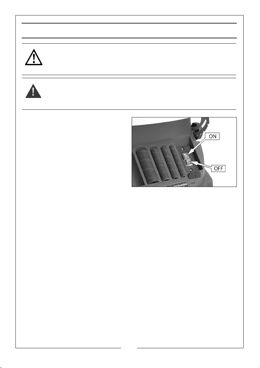
ON-OFF SWITCH
Press green button " - " to turn switch
ON
Press red button " O " to turn switch
OFF.
WHEN THE SANDER IS RUNNING
Before starting your work, watch the
sander while it runs.
If it makes an unfamiliar noise or
vibrates excessively, stop immediately. Switch off and unplug the sander. Do
not restart until identifying and correcting the problem.
Don’t force the sander. It will perform better and safer at its designed rate.
Press workpiece against the sanding sleeve or belt hard enough to begin
sanding without binding.
BEFORE FREEING ANY JAMMED MATERIAL
• Switch OFF ( O ).
• Unplug the sander.
• Wait for all moving parts to stop.
BEFORE LEAVING THE SANDER
• Switch off. Do not leave the sander until the unit comes to a
complete stop.
14
Parts & Service: 020 8988 7400 / E-mail: [email protected] or [email protected]
Page 15
ADJUSTING THE TABLE ANGLE
WARNING: BEFORE PERFORMING ANY ADJUSTMENT, MAKE SURE THE
SANDER IS SWITCHED OFF AND UNPLUGGED FROM THE POWER SUPPLY.
FAILURE TO HEED THIS WARNING COULD RESULT IN SERIOUS PERSONAL
INJURY.
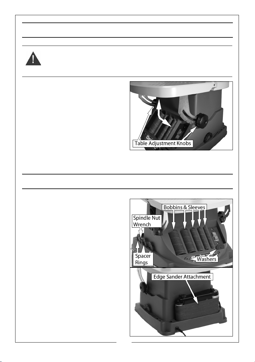
1. Loosen the table adjustment
knobs (one each side) and move
the table to the required angle.
• There are stops on the right
hand bracket at the following
angles 0, 15, 22.5, 30, and 45
degrees.
• Use a protractor or set square
to confirm the angle.
2. Retighten both table adjustment
knobs.
PARTS STORAGE
1. The storage slots on the front are
used to store bobbins/sanding
sleeves and washers.
2. Spindle nut wrench and spacer
rings and the are stored on the
sides.
3. The edge sander is stored at the
rear.
15
Parts & Service: 020 8988 7400 / E-mail: [email protected] or [email protected]
Page 16

TROUBLESHOOTING
Trouble Possible Cause Solution
Sander will not start Sander unplugged from wall Check all plug connections
Fuse blown or circuit breaker
tripped
Cable damaged Replace the cable
Replace fuse or reset circuit
breaker
Sanding belt does
not come up to
speed
Abrasive belt keeps
tearing
Sanded edge not
square
Sanding marks on
wood
Extension cable too light or too
long
Low current Contact a qualified electrician
Belt is running in the wrong
direction
Table not square to sanding
platen
Wrong grit sanding belt Use coarser grit for stock
Feed pressure too great Never force work into sanding
Sanding against the grain Sand with the grain
Replace with adequate size
and length cable
Arrow on the sanding belt and
machine should be pointing in
the same direction
Use a square to adjust table to
sanding platen
removal and fine grit for finish
sanding.
platen
16
Parts & Service: 020 8988 7400 / E-mail: [email protected] or [email protected]
Page 17
MAINTENANCE
WARNING: REMOVE THE PLUG FROM THE MAINS POWER SUPPLY BEFORE
CARRYING OUT ANY ADJUSTMENT, SERVICING OR MAINTENANCE
PERIODICALLY
• Keep the ventilation holes clear and free from blockages.
• Wipe the unit with a damp cloth, do not use abrasive chemicals to
clean the sander.
LUBRICATION
• All of the bearings in this sander are lubricated with a sufficient
amount of high grade lubricant for the life of the unit under normal
operating conditions. Therefore, no further lubrication is required.
REPLACEMENT SANDING SLEEVES
Part Number
Sanding Belt 6500462
Sanding Drums (x 4) 6500464
Sanding Sleeve 80 Grit (x5) 6500466
Sanding Sleeve 150 Grit (x5) 6500468
Sanding Sleeve 240 Grit (x5) 6500470
17
Parts & Service: 020 8988 7400 / E-mail: [email protected] or [email protected]
Page 18

SPECIFICATIONS
Model Number COEBS1
No load speed - Spindle 2000 RPM
No load speed - Belt 1750 RPM
Sanding Table Dimensions: (Depth x Width) 418 x 401 mm
Table Height 334 mm
Bobbin Length 116 mm
Dust Extraction I.D : 36 mm, O.D : 39 mm
Operating Voltage and Frequency 230V @ 50Hz
Input Power @ Rated Load 450W
Sanding Sleeve Diameters ½", ¾", 1", 1½", 2"
Grit grades 80 grit
Sound Pressure level : LpA 76 dB
Sound Power level: LWA 89 dB
Uncertainty Factor K 3 dB
Dimensions (L x W x H) 456 x 417 x 455 mm
Weight 12.4 kg
The details and specifications contained herein, are correct at the time of going
to print. We reserve the right to change specifications without prior notice
18
Parts & Service: 020 8988 7400 / E-mail: [email protected] or [email protected]
Page 19
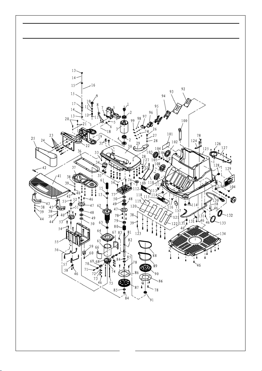
EXPLODED DIAGRAM AND PARTS LIST
Parts & Service: 020 8988 7400 / E-mail: [email protected] or [email protected]
19
Page 20

1 Knob KTCOEB1001
2 Bearing 604 KTCOEB1002
3 Sanding Drum KTCOEB1003
4 Fan KTCOEB1004
5 Hexagon Nuts M5 KTCOEB1005
6 Tension Plate Gasket KTCOEB1006
7 Tension Spring KTCOEB1007
8 Belt Tension Lever KTCOEB1008
9 Tracking Knob KTCOEB1009
10 Rubber Gaskets B KTCOEB1010
11 Gasket KTCOEB1011
12 Spring KTCOEB1012
13 Shaft Circlip 12 KTCOEB1013
14 Drum Axle Shim KTCOEB1014
15 Bearing 601 KTCOEB1015
16 Small Wheel KTCOEB1016
17 Small Drum Axle KTCOEB1017
18 Small Drum Bracket KTCOEB1018
19 Drum Stand KTCOEB1019
20 Cross Recessed Pan
Head Screws
21 External Tooth Lock
Washer
22 Sanding Belt Assembly
Cover
23 Hexagon Socket
Countersunk Head
Screws
24 Hexagon Socket
Countersunk Head
Screws
25 4"X23" Sanding Belt KTCOEB1025
26 Socket Head Cap
Screws
27 Spring Gasket 6mm KTCOEB1027
28 Flat Washer 6mm KTCOEB1028
29 Backstop KTCOEB1029
30 Main Work Bench KTCOEB1030
31 Hexagon Socket
Countersunk Head
Screws
32 Cross Recessed Pan
Head Screws
33 Hexagon Set Screws KTCOEB1033
KTCOEB1020
KTCOEB1021
KTCOEB1022
KTCOEB1023
KTCOEB1024
KTCOEB1026
KTCOEB1031
KTCOEB1032
34 Flexible Slider KTCOEB1034
35 Square Nuts M6 KTCOEB1035
36 Rubber Gasket KTCOEB1036
37 Dust Guide B KTCOEB1037
38 Flat Washer KTCOEB1038
39 Spring Gasket KTCOEB1039
40 Cross Recessed Pan
Head Screws
41 Flexible Work Bench KTCOEB1041
42 Rotary Screw KTCOEB1042
43 Right Angle Board KTCOEB1043
44 Socket Head Cap
Screws
45 Left Angle Board KTCOEB1045
46 Self-tapping Screws KTCOEB1046
47 Bearing Retainer KTCOEB1047
48 Bearing 6203 KTCOEB1048
49 Wool Felt KTCOEB1049
50 Rubber Gasket B KTCOEB1050
51 Shaft Circlip KTCOEB1051
52 Tensioner Assembly KTCOEB1052
53 Positioning Plate
Assembly
54 Self-tapping Screws KTCOEB1054
55 Pulley Bracket KTCOEB1055
56 Cable Assembly (1) KTCOEB1056
57 Cable Assembly (2) KTCOEB1057
58 Wire Crimping Board KTCOEB1058
59 Bridge Reactor KTCOEB1059
60 Self-tapping Screws KTCOEB1060
61 Long Pulley KTCOEB1061
62 Rotor Assembly KTCOEB1062
63 Bearing 608 KTCOEB1063
64 Connecting Plate KTCOEB1064
65 Cylinder KTCOEB1065
66 Magnetic Tile KTCOEB1066
67 Magnetic Tile KTCOEB1067
68 Rear End KTCOEB1068
69 Brush Holder KTCOEB1069
70 Carbon Brush KTCOEB1070
KTCOEB1040
KTCOEB1044
KTCOEB1053
20
Parts & Service: 020 8988 7400 / E-mail: [email protected] or [email protected]
Page 21

71 Carbon Brush Spring KTCOEB1071
72 Crimping Board KTCOEB1072
73 Internal Tooth Lock
Washer s 4
74 Flat Washer 4 KTCOEB1074
75 Self-tapping Screw KTCOEB1075
76 Rubber Dust Washer KTCOEB1076
77 Bearing Cover KTCOEB1077
78 Self-tapping Screws KTCOEB1078
79 Large Bearing Sleeve KTCOEB1079
80 Compression Spring KTCOEB1080
81 Spindle KTCOEB1081
82 Roll Pin KTCOEB1082
83 Woodruff Key KTCOEB1083
84 Circlip 17 KTCOEB1084
85 Output Shaft Washer KTCOEB1085
86 Pulley Damper KTCOEB1086
87 Drive Pulley KTCOEB1087
88 Synchronous Belt KTCOEB1088
89 Synchronous Belt (2) KTCOEB1089
90 Driven Pulley KTCOEB1090
91 Small Bearing Sleeve KTCOEB1091
92 Switch Positioning Plate KTCOEB1092
93 Switch Plate KTCOEB1093
94 Switch Locating Ring
(Down)
95 Switch Locating Ring
(Up)
96 Switch Assembly KTCOEB1096
97 Switch-assisted
Positioning Ring
98 Spring Washers 4 KTCOEB1098
99 Phillips Flat-head Screws KTCOEB1099
100 Wrench KTCOEB1100
101 Warning Label KTCOEB1101
102 Plastic Washers (3) KTCOEB1102
103 Knob KTCOEB1103
104 Hex Nuts M8 KTCOEB1104
105 Flat Washer 8 KTCOEB1105
106 Spring Washer 8 KTCOEB1106
KTCOEB1073
KTCOEB1094
KTCOEB1095
KTCOEB1097
107 Socket Head Cap
Screws
108 Plastic Washer(4) KTCOEB1108
109 Motor Cable Assembly(1) KTCOEB1109
110 Motor Cable Assembly(2) KTCOEB1110
111 Plastic Washer(5) KTCOEB1111
112 Name Plate KTCOEB1112
113 Gasket(2) KTCOEB1113
114 Rubber Foot KTCOEB1114
115 Trademark KTCOEB1115
116 Gasket(3) KTCOEB1116
117 Gasket(1) KTCOEB1117
118 Sanding Sleeve 1 KTCOEB1118
119 Sanding Sleeve 2 KTCOEB1119
120 Sanding Sleeve 3 KTCOEB1120
121 Sanding Sleeve 4 KTCOEB1121
122 Sanding Sleeve 5 KTCOEB1122
123 Allen Screws KTCOEB1123
124 Indexing Plate KTCOEB1124
125 Plastic Base KTCOEB1125
126 Hexagon Set Screws KTCOEB1126
127 Plastic Panel KTCOEB1127
128 Line Card KTCOEB1128
129 Warning Signs (2) KTCOEB1129
130 Power Cable KTCOEB1130
131 Xlsr Type Fixing Clip KTCOEB1131
132 Plastic Washers(2) KTCOEB1132
133 Plastic Washers KTCOEB1133
134 Plastic Bottom Plate KTCOEB1134
KTCOEB1107
0
21
Parts & Service: 020 8988 7400 / E-mail: [email protected] or [email protected]
Page 22

DECLARATION OF CONFORMITY
22
Parts & Service: 020 8988 7400 / E-mail: [email protected] or [email protected]
Page 23

Page 24

 Loading...