

Page 1
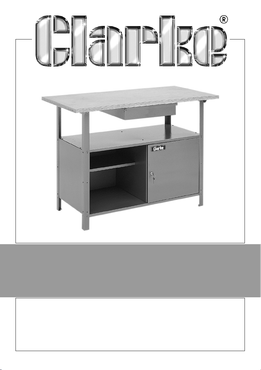
WORKBENCH WITH CABINET & DRAWER
MODEL NO: CWB1250
PART NO: 6500130
ASSEMBLY INSTRUCTIONS
ORIGINAL INSTRUCTIONS GC0917
Page 2
INTRODUCTION
Thank you for purchasing this CLARKE workbench.
Before attempting to use this product, please read this manual thoroughly and
follow the instructions carefully. In doing so you will ensure the safety of yourself
and that of others around you, and you can look forward to your purchase
giving you long and satisfactory service.
Please keep these instructions in a safe place for future reference.
GUARANTEE
This product is guaranteed against faulty manufacture for a period of 12
months from the date of purchase. Please keep your receipt which will be
required as proof of purchase.
This guarantee is invalid if the product is found to have been abused or
tampered with in any way, or not used for the purpose for which it was
intended.
Faulty goods should be returned to their place of purchase, no product can
be returned to us without prior permission.
This guarantee does not effect your statutory rights.
ENVIRONMENTAL PROTECTION
Do not dispose of old products or damaged parts with general household
waste. All tools, accessories and packaging no longer required should be
sorted, taken to a recycling centre and disposed of appropriately.
ASSEMBLY
UNPACKING
Open the carton and lay out the components carefully, identifying them
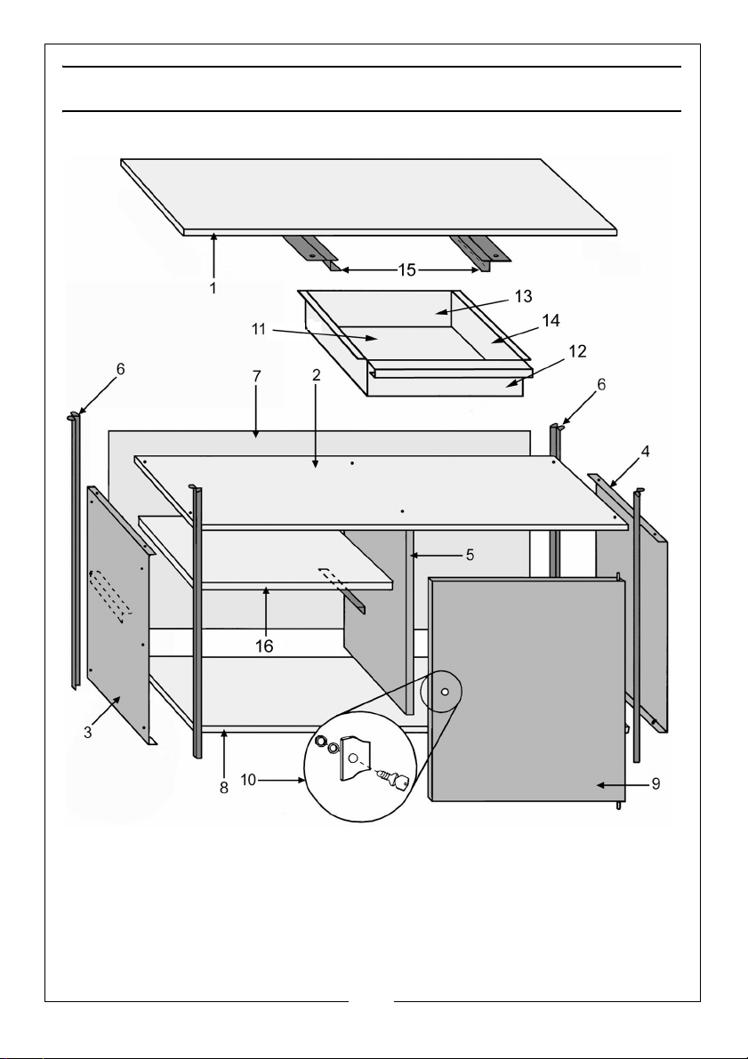
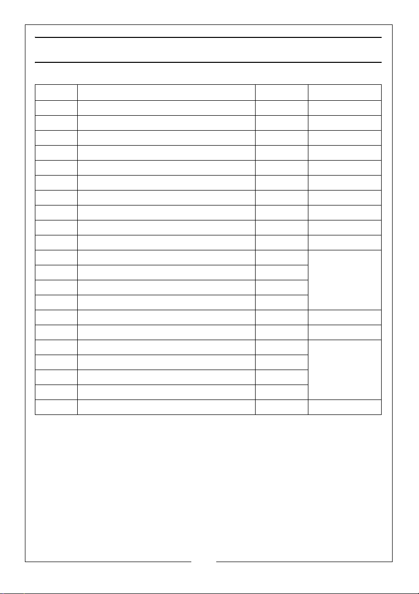
according to the parts list and diagram on pages 6 and 7.
Should any part be damaged or missing, please contact your Clarke dealer
immediately for replacement.
2
Parts & Service: 020 8988 7400 / E-mail: [email protected] or [email protected]
Page 3
CONSTRUCTION
The cabinet body is constructed from 6 panels plus the door. The top and
bottom panels are identical, but the side panels are of two types, one with a
shelf support and one without. The unit can be assembled either with the open
shelf to the left or right, with the closed cupboard on the other side.
Care must be taken to ensure they are assembled correctly by taking note of
the instructions and referring to the appropriate diagram.
All fixing bolts should be entered from the outside and secured on the inside
by the flat washers and nuts provided. Assembly should be carried out with all
nuts finger tight only - DO NOT tighten the nuts until the structure is fully
assembled as described in the instructions.
You will find it easier and more comfortable to assemble the cabinet,
complete with legs, on a workbench if available. Additionally, it is easier and
quicker if an assistant screws on the nuts from inside the cabinet whilst the bolt
is held on the outside.
NOTES:
1. Decide whether you require the enclosed cupboard to be on the left or
right side of the assembly.
2. Assembly is simplified if an extra pair of hands is available.
3. All fixing bolts should be finger tight ONLY, until the complete structure is
assembled.
4. Assemble on a workbench with suitable free working area.
The assembly procedure is as follows:
THE CABINET
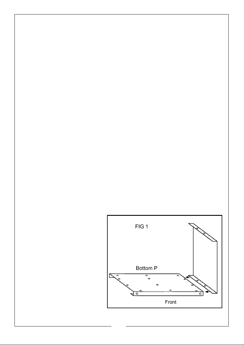
The front edge of each top/
bottom panel is folded to form
a channel, as shown in fig 1.
1. Lay one such panel,
(channel facing
downwards), with a side
panel positioned alongside
as shown.
• The bottom panel should sit
on top of the lower lip of
the side panel.
2. Secure with two bolts, flat
washers and nuts.
3
Parts & Service: 020 8988 7400 / E-mail: [email protected] or [email protected]
Page 4
3. Attach the opposite side
panel in a similar manner.
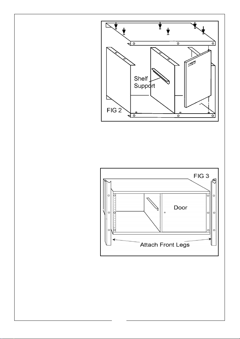
4. Add the centre panel,
noting that the shelf
support bracket must
correspond with the
bracket on the end
panel.
5. Locate the door lower
hinge pin into the hole in
the lower panel, then
place the top panel on
top of the two side and
centre panel as shown in
Fig 2, locating the door
top hinge pin in the hole
in the upper panel as you do so.
6. Secure the top panel at the sides and centre with bolts, nuts & washers in
the holes shown arrowed in Fig 2.
7. Lay the structure on its back so that you can easily bolt on the front legs as
shown in Fig 3, tightening the fastenings only finger tight.
8. With the two front legs
bolted on, turn the
structure over onto its
front.
9. Place the back panel in
position and hold in
place using a bolt
through the centre hole
only on the top and
bottom panels. Secure
with a washer and nut
from inside the unit.
10. Bolt on both the rear legs,
securing the back panel
as you do so.
11. Stand the structure on its feet and rock it to ensure that no particular part is
under strain and so that it stands evenly. Check that the door opening is
square and that the door closes freely. If not, adjust the structure by hand
so that it is square, then proceed to tighten all the securing nuts.
12. Finally place the structure on its feet and test for stability, adjust any bolts,
as necessary, and secure by tightening the nuts.
4
Parts & Service: 020 8988 7400 / E-mail: [email protected] or [email protected]
Page 5
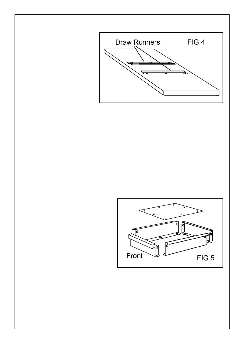
THE TABLE TOP
1. Turn the table top face
down and attach the
two drawer runners as
shown in fig 4, using
three wood-screws
each side in the predrilled holes in the table
top.
2. The table is now ready
to be assembled to the
cabinet.
3. With the table top remaining face down, position the cabinet on top with
the feet uppermost.
NOTE: The front of the table top is the edge closest to the drawer runners.
Take care to align this with the front of the cabinet.
4. Line up the holes in the legs with the pre-drilled holes in the table top and
locate with wood-screws. Tighten fully.
5. Turn the structure back onto its feet.
THE DRAWER & SHELF
The drawer comprises:
2 x Side Panels, I x Front Panel, 1 x Back Panel, 1 x Bottom Panel
1. Having identified the various
parts as in Fig 5, bolt the side
panels to the front panel as
shown, then add the back
panel with all fastenings only
finger tight.
2. Drop in the bottom panel and
secure with bolts, nuts and
washers.
3. Ensure the drawer is square
before tightening all the nuts.
4. Slide the drawer into place beneath the table top.
5. Position the shelf on the shelf supports.
Your workbench is now fully assembled and ready for use.
5
Parts & Service: 020 8988 7400 / E-mail: [email protected] or [email protected]
Page 6
Page 7
COMPONENT PARTS
Item Description Qty Part No
1 Table Top 1 RO125001
2 Top Panel 1 RO125002
3 Left hand Side Panel 1 RO125003
4 Right Hand Side Panel 1 RO125004
5 Centre Panel 1 RO125005
6 Leg 4 RO125006
7 Rear Panel 1 RO125007
8 Bottom Panel 1 RO125008
9 Door Panel 1 RO125009
10 Door Lock Assembly 1 RO125010
11 Drawer Bottom 1
12 Draw Front 1
13 Drawer Back 1
14 Drawer Side 2
15 Drawer Runner 2 RO125014
16 Shelf 1 RO125015
Woodscrew (runners) 6
Machine Screw 36
Flat Washer 36
Nut 36
Woodscrew (legs) 8 RO125017
RO125011
RO125016
7
Parts & Service: 020 8988 7400 / E-mail: [email protected] or [email protected]
Page 8

 Loading...