

Page 1
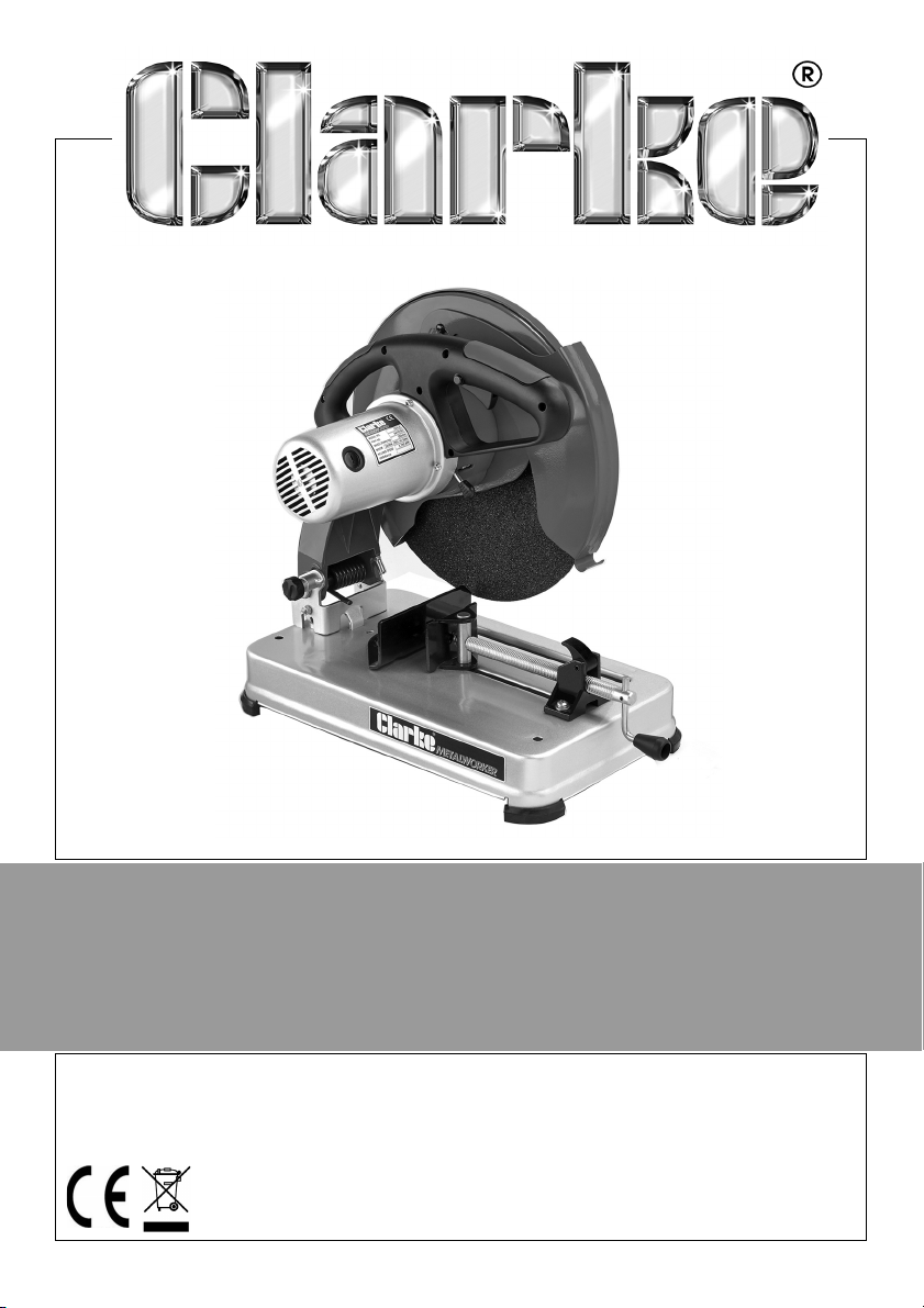
ABRASIVE CUT-OFF SAW
MODEL NO: CCO14B
PART NO: 6470160
OPERATION & MAINTENANCE
INSTRUCTIONS
GC0616
Page 2
INTRODUCTION
Thank you for purchasing this CLARKE Abrasive Cut-Off Saw which is suitable
for cutting ferrous metals which are compatible with the type of abrasive
wheel fitted.
Before attempting to use this product, please read this manual thoroughly and
follow the instructions carefully. In doing so you will ensure the safety of yourself
and that of others around you, and you can look forward to your purchase
giving you long and satisfactory service.
GUARANTEE
This product is guaranteed against faulty manufacture for a period of 12
months from the date of purchase. Please keep your receipt which will be
required as proof of purchase.
This guarantee is invalid if the product is found to have been abused or
tampered with in any way, or not used for the purpose for which it was
intended.
Faulty goods should be returned to their place of purchase, no product can
be returned to us without prior permission.
This guarantee does not effect your statutory rights.
ENVIRONMENTAL RECYCLING POLICY
Through purchase of this product, the customer is taking on the
obligation to deal with the WEEE in accordance with the WEEE
regulations in relation to the treatment, recycling & recovery and
environmentally sound disposal of the WEEE.
In effect, this means that this product must not be disposed of with general
household waste. It must be disposed of according to the laws governing
Waste Electrical and Electronic Equipment (WEEE) at a recognised disposal
facility.
2
Parts & Service: 020 8988 7400 / E-mail: [email protected] or [email protected]
Page 3

GENERAL POWER TOOL SAFETY WARNINGS
WARNING: READ ALL INSTRUCTIONS. FAILURE TO FOLLOW ALL
INSTRUCTIONS LISTED BELOW MAY RESULT IN ELECTRIC SHOCK, FIRE AND/
OR SERIOUS INJURY. THE TERM “POWER TOOL” IN THE WARNINGS REFERS
TO YOUR SAW.
Save all warnings and instructions for future reference.
1) WORK AREA SAFETY
a. Keep work area clean and well lit. Cluttered or dark areas invite
accidents.
b. Do not operate power tools in explosive atmospheres, such as in the
presence of flammable liquids, gases or dust. Power tools create sparks
which may ignite the dust or fumes.
c. Keep children and bystanders away while operating a power tool.
Distractions can cause you to lose control.
2) ELECTRICAL SAFETY
a. Power tool plugs must match the outlet. Never modify the plug in any
way. Do not use any adapter plugs with earthed (grounded) power
tools. Unmodified plugs and matching outlets will reduce risk of electric
shock.
b. Avoid body contact with earthed or grounded surfaces, such as pipes,
radiators, ranges and refrigerators. There is an increased risk of electric
shock if your body is earthed or grounded.
c. Do not expose power tools to rain or wet conditions. Water entering a
power tool will increase the risk of electric shock.
d. Do not abuse the cable. Never use the cable for carrying, pulling or
unplugging the power tool. Keep cable away from heat, oil, sharp
edges or moving parts. Damaged or entangled cables increase the risk
of electric shock.
e. When operating a power tool outdoors, use an extension cable suitable
for outdoor use. Use of a cable suitable for outdoor use reduces the risk
of electric shock.
f. If operating a power tool in a damp location is unavoidable, use a
residual current device (RCD) protected supply. Use of an RCD reduces
the risk of electric shock.
3
Parts & Service: 020 8988 7400 / E-mail: [email protected] or [email protected]
Page 4

3) PERSONAL SAFETY
a. Stay alert, watch what you are doing and use common sense when
operating a power tool. Do not use a power tool while you are tired or
under the influence of drugs, alcohol or medication. A moment of
inattention while operating power tools may result in serious personal
injury.
b. Use personal protective equipment. Always wear eye protection.
Protective equipment such as dust mask, non-skid safety shoes, hard
hat, or hearing protection used for appropriate conditions will reduce
personal injuries.
c. Prevent unintentional starting. Ensure the switch is in the off-position
before connecting to power source and/or battery pack, picking up or
carrying the tool. Carrying power tools with your finger on the switch or
energising power tools that have the switch on invites accidents.
d. Remove any adjusting key or wrench before turning the power tool on.
A wrench or a key left attached to a rotating part of the power tool
may result in personal injury.
e. Do not overreach. Keep proper footing and balance at all times. This
enables better control of the power tool in unexpected situations.
f. Dress properly. Do not wear loose clothing or jewellery. Keep your hair,
clothing and gloves away from moving parts. Loose clothes, jewellery or
long hair can be caught in moving parts.
g. If devices are provided for the connection of dust extraction and
collection facilities, ensure these are connected and properly used. Use
of dust collection can reduce dust-related hazards.
4) POWER TOOL USE AND CARE
a. Do not force the power tool. Use the correct power tool for your
application. The correct power tool will do the job better and safer at
the rate for which it was designed.
b. Do not use the power tool if the switch does not turn it on and off. Any
power tool that cannot be controlled with the switch is dangerous and
must be repaired.
c. Disconnect the plug from the power source and/or the battery pack
from the power tool before making any adjustments, changing
accessories, or storing power tools. Such preventive safety measures
reduce the risk of starting the power tool accidentally.
d. Maintain power tools. Check for misalignment or binding of moving
parts, breakage of parts and any other condition that may affect the
power tool's operation. If damaged, have the power tool repaired
before use. Many accidents are caused by poorly maintained power
tools.
4
Parts & Service: 020 8988 7400 / E-mail: [email protected] or [email protected]
Page 5

e. Store idle power tools out of the reach of children and do not allow
persons unfamiliar with the power tool or these instructions to operate
the tool. Power tools are dangerous in the hands of untrained users.
f. Keep cutting tools sharp and clean. Properly maintained cutting tools
with sharp cutting edges are less likely to bind and are easier to control.
g. Use the power tool, accessories and tool bits etc. in accordance with
these instructions, taking into account the working conditions and the
work to be performed. Use of the power tool for operations different
from those intended could result in a hazardous situation.
5) SERVICE
a. Have your power tool serviced by a qualified repair person using only
identical replacement parts. This will ensure that the safety of the power
tool is maintained.
ADDITIONAL WARNINGS FOR CUT-OFF SAWS
1. IMPORTANT: You should not operate this machine unless you are thoroughly
familiar with metal cutting saws. If there is any doubt whatsoever, you
should consult a qualified person.
2. Do not operate the machine until it is completely assembled, and this
entire manual, has been read and understood.
3. Ensure the proper electrical regulations are followed.
4. Ensure the abrasive disc is securely mounted in accordance with these
instructions, before connecting to a power supply.
5. DO NOT over tighten the abrasive disc. This can cause stress, and could
lead to the wheel shattering when under load.
6. Always check the abrasive disc for cracks before use.
7. Before switching the machine on, ALWAYS ensure the work is properly
secured, ALWAYS use the vice, NEVER hand hold a workpiece.
8. Make all adjustments with the power OFF.
9. When starting a cut, always ease the tool into the work. A harsh or sudden
impact could shatter the abrasive disc.
10. Ensure the abrasive disc reaches maximum speed before beginning a cut.
11. Never use the machine with the guards removed.
12. Ensure you use the correct type of abrasive disc for the type of material
being cut. Metal cutting & masonry abrasive discs are available from your
Clarke dealer. NEVER cut magnesium, wood, or non-ferrous metals.
5
Parts & Service: 020 8988 7400 / E-mail: [email protected] or [email protected]
Page 6
ELECTRICAL CONNECTIONS
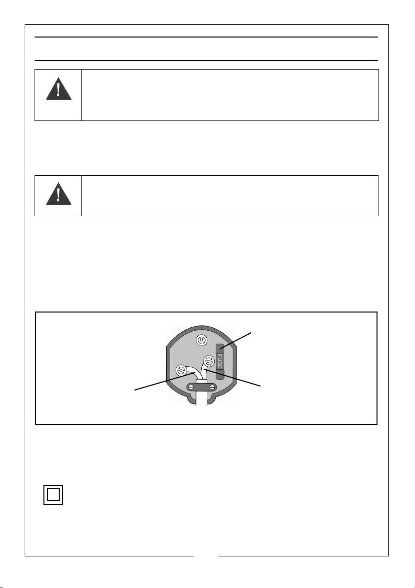
Plug must be BS1363/A approved.
Always fit a 13 Amp fuse.
Ensure that the outer sheath of the cable is firmly held by the clamp
Neutral
(Blue)
Live
(Brown)
WARNING: READ THESE ELECTRICAL SAFETY INSTRUCTIONS
THOROUGHLY BEFORE CONNECTING THE PRODUCT TO THE MAINS
SUPPLY.
This product is provided with a standard 13 amp, 230 volt (50Hz), BS 1363 plug,
for connection to a standard, domestic electrical supply. Should the plug
need changing at any time, ensure that a plug of identical specification is
used.
WARNING: THE WIRES IN THE POWER CABLE OF THIS PRODUCT ARE
COLOURED IN ACCORDANCE WITH THE FOLLOWING CODE:
BLUE = NEUTRAL BROWN = LIVE
If the colours of the wires in the power cable of this product do not correspond
with the markings on the terminals of your plug, proceed as follows.
• The wire which is coloured Blue must be connected to the terminal
which is marked N or coloured Black.
• The wire which is coloured Brown must be connected to the terminal
which is marked L or coloured Red.
We strongly recommend that this machine is connected to the mains supply
via a Residual Current Device (RCD)
If in any doubt, consult a qualified electrician. DO NOT attempt any repairs
yourself.
Parts & Service: 020 8988 7400 / E-mail: [email protected] or [email protected]
This symbol indicates that this is a Class II product, and does not require
an earth connection.
6
Page 7
UNPACKING AND ASSEMBLY
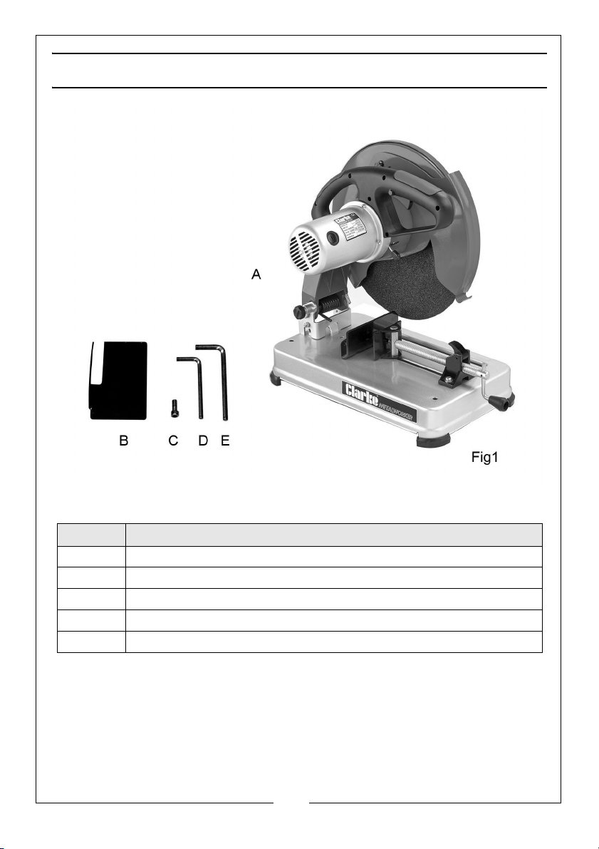
Item Description
A Cut-off Saw (with abrasive cutting disc supplied fitted)
BSpark Deflector
C M5 Hex Socket head screw
D Hex wrench 5mm
E Hex wrench 8mm
Unpack the saw carefully and ensure that all items are accounted for
according to the above list. In the event of any deficiencies you should
contact your Clarke dealer immediately.
7
Parts & Service: 020 8988 7400 / E-mail: [email protected] or [email protected]
Page 8
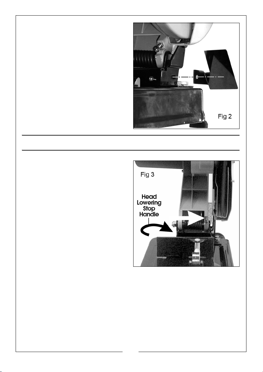
Fit the Spark Deflector as shown in
fig.2, securing with the M5 hex. head
screw.
FEATURES
1. A stop is provided to restrict the
height to which the arm may be
lowered. The stop is in the form of
a bolt, arrowed in fig. 3 which
should not require adjusting.
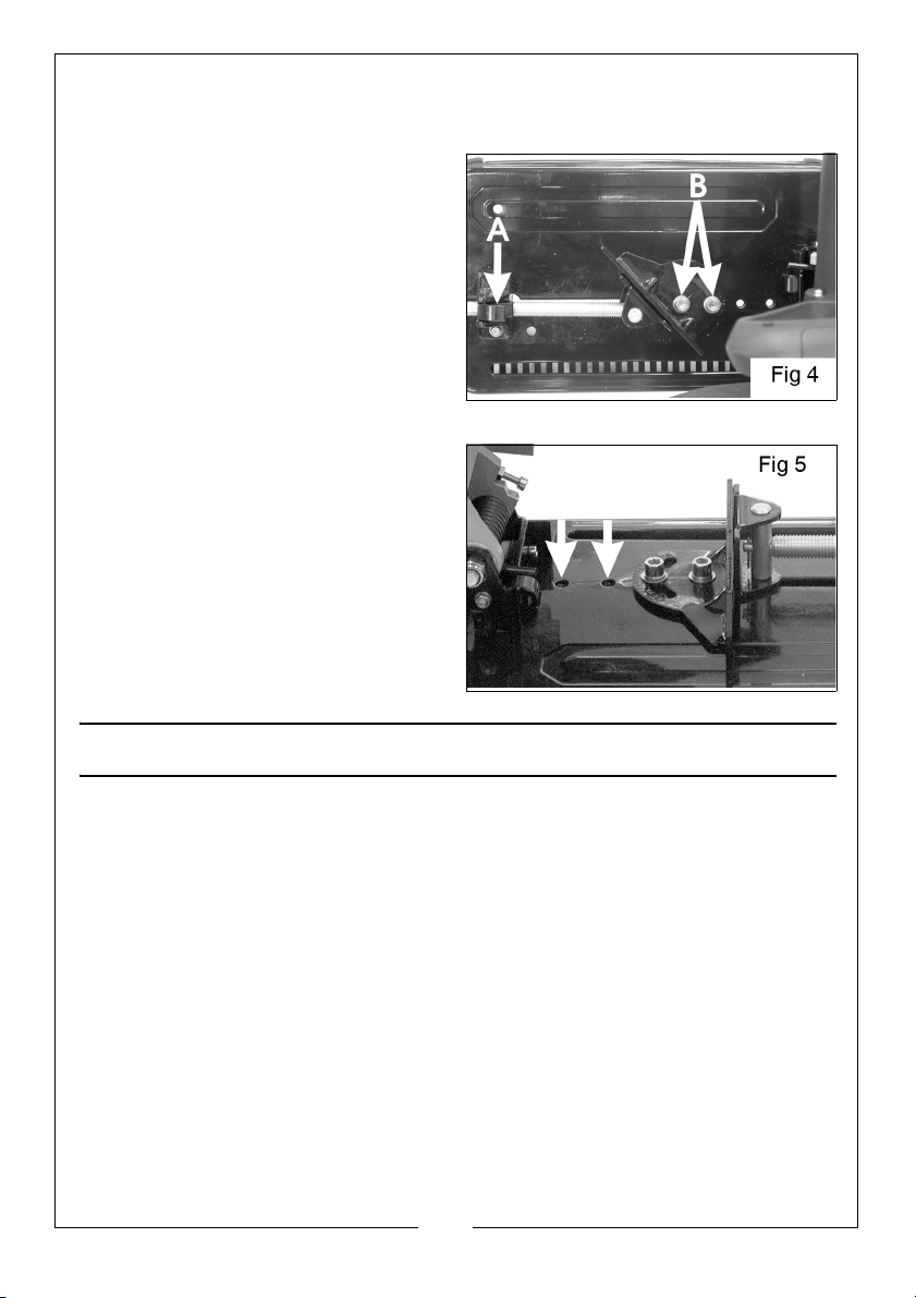
2. The vice is provided with a quick
adjust device (shown at A, fig.4).
The block, through which the
screw passes, pivots, and may be
lifted off the screw thread. This
releases the screw, and hence
the vice jaw which may then be
quickly moved into contact with
the work. The block is then flipped
back into position and the work
clamped in the normal way by
using the handle.
3. A latch, to prevent the head from being lowered, is provided. Turn the
plastic handle at the rear of the unit, indicated in fig 3, to engage the
latch.
Before carrying out any adjustments or maintenance, ensure the saw is
disconnected from the power supply.
8
Parts & Service: 020 8988 7400 / E-mail: [email protected] or [email protected]
Page 9
ADJUSTING THE VICE
A. BEVEL CUTTING
The vice may be moved up to 45° for
bevel cutting.
To set the required angle, slacken off
the two bolts securing the fixed vice
jaw (shown at B), and swivel the jaw
to the appropriate angle according
to the scale provided. Use a set
square or angle gauge set against
the abrasive disc if absolute
accuracy is required. Tighten the two
securing bolts when satisfied.
B. POSITIONING THE FIXED VICE JAW
The fixed jaw may be fixed in one of
three positions to accommodate
larger workpieces.
Undo and remove the two screws
securing the jaw and reposition as
desired, using the bolt holes arrowed
in Fig.5 to secure the jaw.
OPERATION
Ensuring the workpiece is properly clamped and observing all precautions
previously mentioned, switch ON by pressing the safety lock button before
pulling the ON/OFF trigger switch upwards. Allow the wheel to reach full speed
then gently lower it on to the work. DO NOT try to cut too harshly.
The switch is a ‘dead man’ type and the motor will stop when it is released.
NOTE: Take great care when cutting with a new wheel. DO NOT press too
heavily particularly at the end of a cut.
9
Parts & Service: 020 8988 7400 / E-mail: [email protected] or [email protected]
Page 10
MAINTENANCE AND SERVICING
WARNING: BEFORE PERFORMING ANY MAINTENANCE TASKS ENSURE THE
PLUG HAS BEEN REMOVED FROM THE MAINS SUPPLY.
Before use, always check the condition of the abrasive disc to ensure there
are no cracks or badly pitted edges. If in doubt, renew the wheel.
CHANGING THE ABRASIVE DISC
IMPORTANT: Ensure the replacement disc is rated above the rated speed of
the machine.
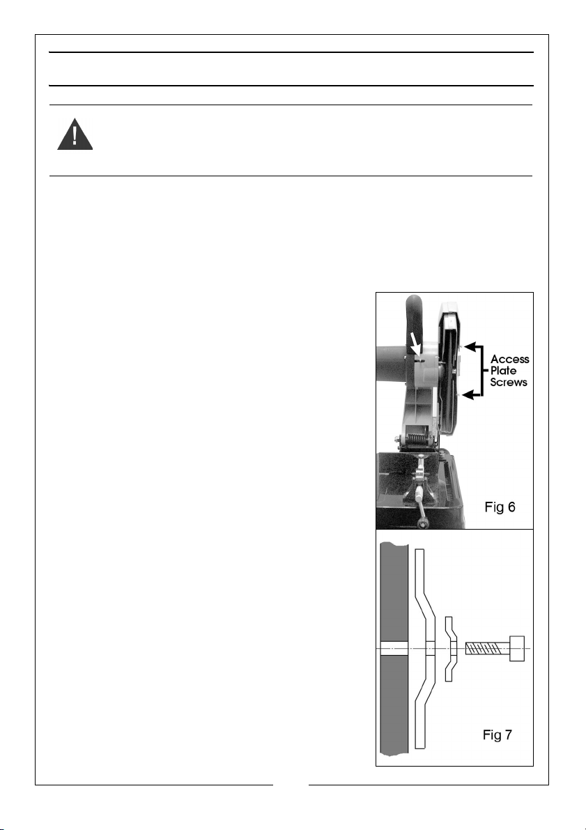
Having disconnected the power supply, Raise the
Upper Blade Guard by hand as high as possible,
then slide the bar, arrowed in fig.6, across, so that it
retains the Blade Guard in place as shown.
Slacken off the two screws which secure the
abrasive disc centre bolt access plate shown in fig
6, and remove the plate.
Using the 8mm hex. wrench, undo and remove the
abrasive disc centre bolt, then remove the washer
and flange. Finally, carefully remove the abrasive
disc.
Reassemble in reverse order, ensuring the disc and
flange are correctly mounted on the flats on the
shaft with the flange and washer oriented as
shown in fig.7, Take great care not to over tighten
the centre bolt.
Refer to your CLARKE dealer if internal
maintenance is required.
10
Parts & Service: 020 8988 7400 / E-mail: [email protected] or [email protected]
Page 11
CHANGING THE CARBON BRUSHES
Maintenance to the motor is limited to changing
the carbon brushes.
These will naturally wear with use and require
replacing. They should be checked periodically as
follows:
1. Unscrew and remove the plastic covers on the
end of the motor with a screwdriver.
2. Pull out the brushes complete with springs and
retainers.
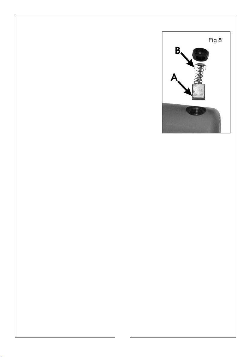
3. Check the brush length, if the ‘wear line’
cannot be seen (‘A’ fig.8), the pair should be
renewed.
4. Replace the brushes, taking care to ensure that
the tabs on the end of the spring retainer (‘B’
fig.8), correctly enter the elongated chamber as you push it in and screw
on the cap.
11
Parts & Service: 020 8988 7400 / E-mail: [email protected] or [email protected]
Page 12
SPECIFICATIONS
MODEL CCO14B
Voltage 230 V AC @ 50Hz
Input power 2200 Watts
Current Rating 10 Amps
No-load speed (single speed with soft
start)
Weight 18 kg
Dimensions (L x W x H) 545 (head lowered) x 308 x 423 mm
Max cutting dimensions (mm)
Sound Pressure Level (LPA) 94.3 dB(A)
Sound Power Level (LWA) 107.3 dB(A)
Sound Uncertainty Value (K) 3 dB(A)
Vibration 2.526 m/s²
Vibration Uncertainty Value (K) 1.5 m/s²
3750 rpm
Round: @90
Square: @90
Rect: @90
o
o
100dia @45o 55dia
o
90sq @45o 70 sq
90 x 170 @45o 70x90
12
Parts & Service: 020 8988 7400 / E-mail: [email protected] or [email protected]
Page 13
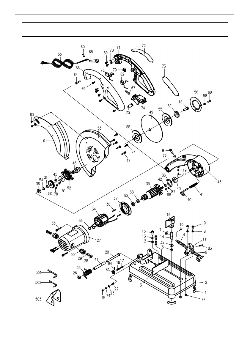
PARTS DIAGRAM
CUTTING DISCS FOR THE CCO14B
14” (350mm) cutting discs - Part Number: 6470800
13
Parts & Service: 020 8988 7400 / E-mail: [email protected] or [email protected]
Page 14
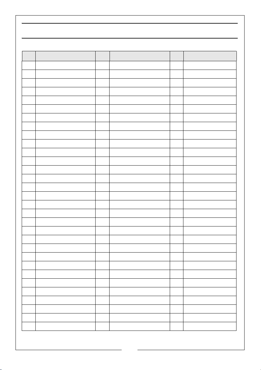
PARTS LIST
No Description No Description No Description
1 Rubber Foot 32 Washer 8mm 63 Screw M6 x 16
2 Base 33 Pan head screw M5x40 64 Self-tapping screw
3 Fence 34 Stator 65 Cable
4 Vice Screw 35 Ring Terminal 66 Handle cover
5 Locknut M8 36 Self-tapping screw 67 Leader wire
6 Support Bracket 37 Baffle 68 Cable gland
7 Washer 8mm 38 Bearing 6000-2Z 69 Self-tapping screw
8 Spring Lockwasher 8m 39 Armature 70 Cable clamp
9 Panhead Screw M8 x30 40 Spindle Lock 71 Handle support
10 Split Cotter Pin 2x20 41 Spring 72 Soft Grip
11 Vice Nut 42 Circlip 15mm 73 Soft Grip
12 Washer 10mm 43 Bearing 6202.RS 74 Switch assembly
13 Spring Washer 10mm 44 Screw 75 Switch Button
14 Pin 45 Screw M5x10 76 Soft Start
15 Screw M10 x 25 46 Cutting Arm 77 Nut M8
16 Vice Plate 47 Pan head screw M5 x25 78 Key 6 x 14
17 Cutting Arm Lock 48 Output shaft 79 Terminal block
18 Spring 49 Cutting Disc 80 Self-tapping screw
19 Nut M6 50 Gear 81 Stopper knob
20 Bolt M12 x 125 51 Bearing 6203-2Z 82 Bush
21 Hollow Shaft 52 Bearing Holder 83 Roll Pin
22 Screw M6 x 16 53 Upper Guard 84 Roll Pin
23 Flat Washer 54 Circlip 17mm 85 O-ring Buckle
24 Spring Washer 6mm 55 Retaining disc 86 Bearing Cover
25 Torsion Spring 56 Center cover 87 Washer
26 Locknut M12 57 Pan head screw M5 x18 88 Pan head screw M4
27 Housing 58 Locknut M6 501 Wrench 8mm
28 Brush Holder Cap 59 Washer 502 Wrench 5mm
29 Carbon Brush 60 Screw M6 x 10 503 Spark deflector
30 Brush Holder 61 Upper Guard
31 Washer 62 Capacitor
14
Parts & Service: 020 8988 7400 / E-mail: [email protected] or [email protected]
Page 15
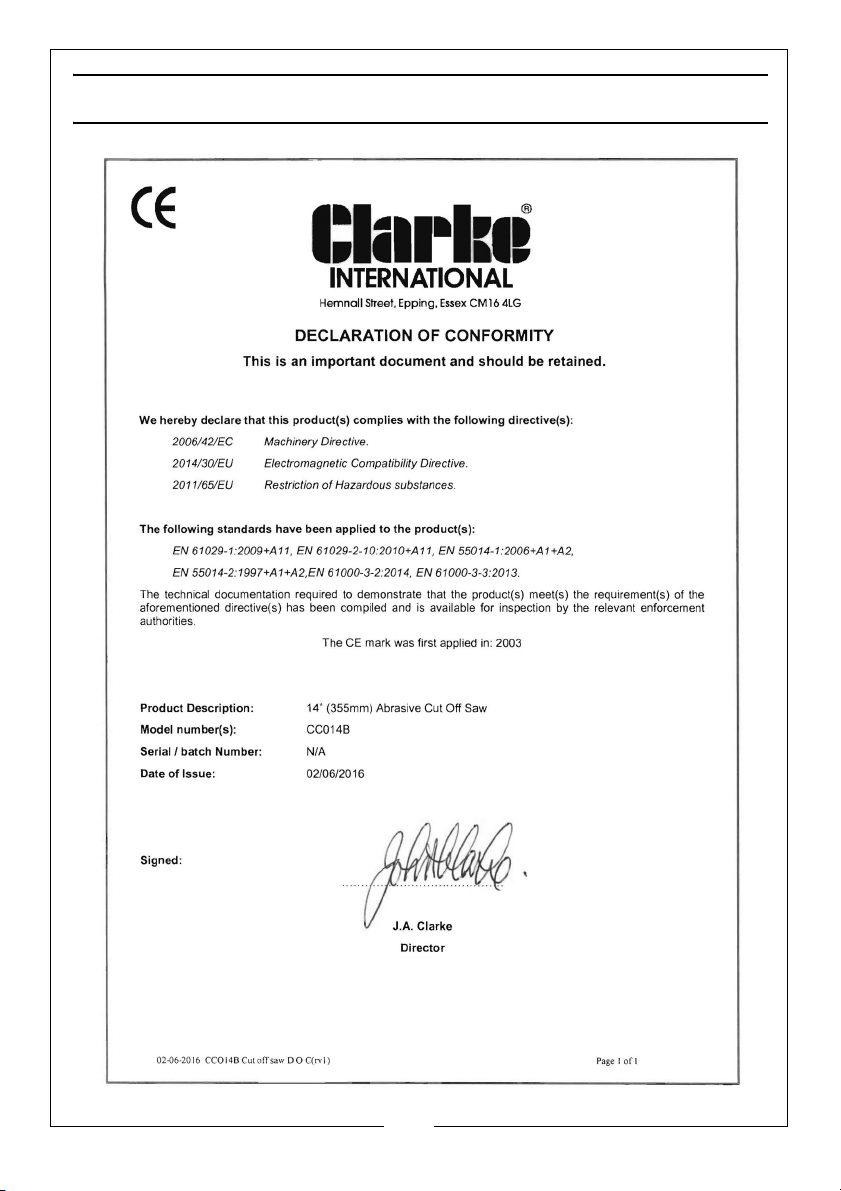
DECLARATION OF CONFORMITY
15
Parts & Service: 020 8988 7400 / E-mail: [email protected] or [email protected]
Page 16
 Loading...