

Page 1
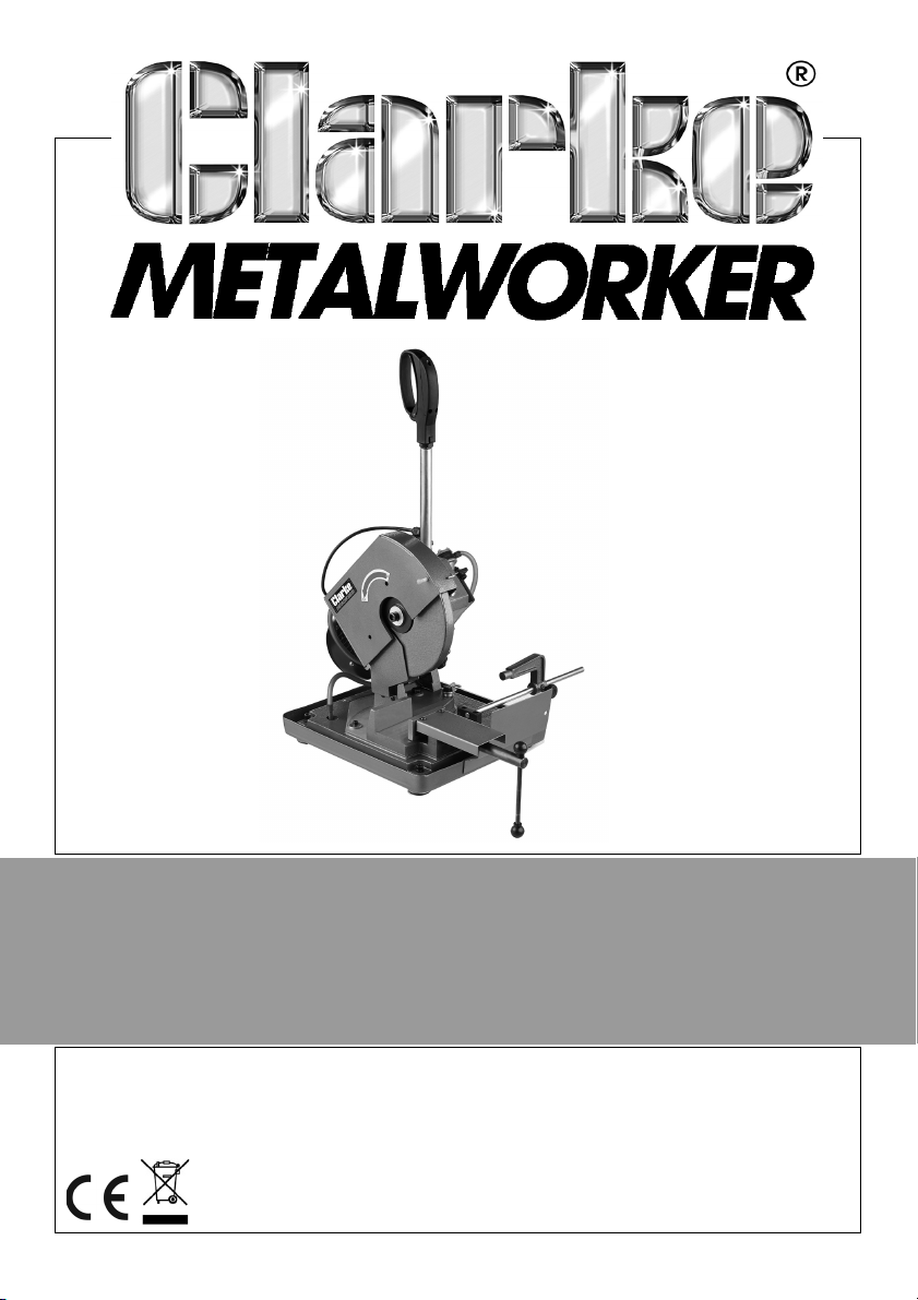
PORTABLE METAL CUTTING CIRCULAR SAW
MODEL NO: CPMCS1
PART NO: 6462360
OPERATION & MAINTENANCE
INSTRUCTIONS
ORIGINAL INSTRUCTIONS GC1020 - REV 3
Page 2
INTRODUCTION
Thank you for purchasing this CLARKE product. The tool is intended for cutting
iron, steel and other ferrous metals with the appropriate saw blades.
Before attempting to use this product, please read this manual thoroughly and
follow the instructions carefully. In doing so you will ensure the safety of yourself
and that of others around you, and you can look forward to your purchase
giving you long and satisfactory service.
GUARANTEE
This product is guaranteed against faulty manufacture for a period of 12
months from the date of purchase. Please keep your receipt which will be
required as proof of purchase.
This guarantee is invalid if the product is found to have been abused or
tampered with in any way, or not used for the purpose for which it was
intended.
Faulty goods should be returned to their place of purchase, no product can
be returned to us without prior permission.
This guarantee does not effect your statutory rights.
ENVIRONMENTAL RECYCLING POLICY
Through purchase of this product, the customer is taking on the
obligation to deal with the WEEE in accordance with the WEEE
regulations in relation to the treatment, recycling & recovery and
environmentally sound disposal of the WEEE.
In effect, this means that this product must not be disposed of with general
household waste. It must be disposed of according to the laws governing
Waste Electrical and Electronic Equipment (WEEE) at a recognised disposal
facility.
2
Parts & Service: 020 8988 7400 / E-mail: [email protected] or [email protected]
Page 3
CONTENTS
The following items should be supplied in the carton. If any parts are missing,
do not operate your saw until the missing parts are obtained.
1 x Metal Saw 1 x Clarke Instruction Manual
1 x HSS Blade - 225 x 1.9 x 32 x 150T (fitted) 1 x Block Plate
1 x Bar Stop, Rod 1 x 10mm Hex Key
1 x Bar Stop
SAFETY WARNINGS
WARNING: WHEN USING ELECTRIC TOOLS, BASIC SAFETY PRECAUTIONS,
INCLUDING THE FOLLOWING, SHOULD ALWAYS BE FOLLOWED TO REDUCE
THE RISK OF FIRE, ELECTRIC SHOCK AND PERSONAL INJURY. READ ALL
THESE INSTRUCTIONS BEFORE OPERATING THIS PRODUCT AND SAVE THESE
INSTRUCTIONS.
1. Keep work area clean. Cluttered
areas and benches invite injuries.
2. Consider work area environment.
Do not expose power tools to rain.
Do not use power tools in damp or
wet locations. Keep work area well
lit. Do not use power tools where
there is risk to cause fire or
explosion.
3. Guard against electric shock.
Avoid body contact with earthed
or grounded surfaces (e.g. pipes,
radiators, ranges, refrigerators).
4. Keep children away. Do not let
visitors touch the tool or extension
cable. All visitors should be kept
away from work area.
5. Store idle tools. When not in use,
tools should be stored in a dry, high
or locked up place, out of reach of
children.
Parts & Service: 020 8988 7400 / E-mail: [email protected] or [email protected]
6. Do not force the tool. It will do the
job better and safer at the rate for
which it was intended.
7. Use the right tool. Do not force
small tools or attachments to do
the job of a heavy duty tool. Do
not use tools for purposes not
intended; for example, do not use
circular saws to cut tree limbs or
logs.
8. Dress properly. Do not wear loose
clothing or jewellery, they can be
caught in moving parts. Non-skid
footwear are recommended when
working outdoors. Wear protecting
hair covering to contain long hair.
9. Use safety glasses and hearing
protection. Also use face or dust
mask if the cutting operation is
dusty.
10. Do not abuse the cable. Never
carry the tool by the cord or yank it
3
Page 4

to disconnect it from the socket.
Keep the cord away from heat, oil
and sharp edges.
11. Secure work. Use clamps or a vice
to hold the work. It is safer than
using your hand and it frees both
hands to operate the tool.
12. Do not overreach. Keep proper
footing and balance at all times.
13. Maintain tools with care. Keep
cutting tools sharp and clean for
better and safer performance.
Follow instructions for lubrication
and changing accessories. Inspect
tool cord periodically and if
damaged have it repaired by an
authorized service facility. Inspect
extension cords periodically and
replace, if damaged. Keep
handles dry, clean and free from
oil and grease.
14. Disconnect tool when not in use,
before servicing, and when
changing accessories such as
blades, bits and cutters.
15. Remove adjusting keys and
wrenches. Form the habit of
checking to see that keys and
adjusting wrenches are removed
from the tool before turning it on.
16. Avoid unintentional starting. Do not
carry a plugged-in tool with a
finger on the switch. Ensure the
switch is off when plugging in.
17. Use outdoor extension leads. When
tool is used outdoors, use only
extension cords intended for
outdoor use.
18. Stay alert. Watch what you are
doing. Use common sense. Do not
operate the tool when you are
tired.
19. Check damaged parts. Before
further use of the tool, a guard or
other part that is damaged should
be carefully checked to determine
that it will operate properly and
perform its intended function.
Check for alignment of moving
parts, free running of moving parts,
breakage of parts, mounting and
any other conditions that may
affect its operation. A guard or
other part that is damaged should
be properly repaired or replaced
by an authorized service centre
unless otherwise indicated in this
instruction manual. Have defective
switches replaced by an
authorised service facility. Do not
use the tool if the switch does not
turn it on and off
20. Have your tool repaired by a
qualified person. This electric tool is
in accordance with the relevant
safety requirements. Repairs should
only be carried out by qualified
persons using original spare parts,
otherwise this may result in
considerable danger to the user.
4
Parts & Service: 020 8988 7400 / E-mail: [email protected] or [email protected]
Page 5
ADDITIONAL SAFETY RULES FOR CUTTING TOOLS
1. Use only correct blades from your
Clarke dealer. Never use abrasive
cut-off wheel or other types of saw
blades.
2. Check the blade carefully for
cracks or damage before
operation. Replace a cracked or
damaged blade immediately.
3. Never secure the safety cover
(safety guard) in an open position.
Always be sure that the safety
cover moves smoothly before
operation. Any irregular operation
of the safety cover should be
corrected immediately. Do not use
the saw without guards in position.
4. Make sure guard lock is released
before the switch is turned on.
5. Before using the tool on an actual
workpiece, let it run for a while.
Watch for vibration or wobbling
that could indicate poor
installation or a poorly balanced
blade.
6. Keep your hands and body away
from rotating blade.
7. Always secure the workpiece with
the vice.
8. Make sure the blade is not
contacting the workpiece before
switching on.
9. Watch out for flying sparks when
operating. They can cause injury or
ignite combustible materials.
10. Do not touch the blade,
workpiece or swarf immediately
after operation; they may be
extremely hot and could burn your
skin.
11. If the blade stops during operation,
makes an odd noise, or begins to
vibrate, switch off the tool
immediately. Then check the tool
and blade.
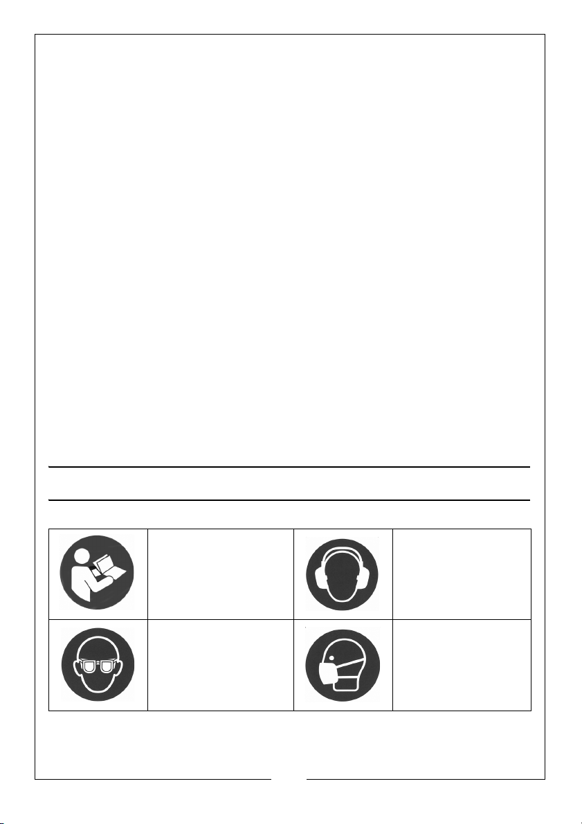
SAFETY SYMBOLS
Read this instruction
booklet before use
Wear eye protection Wear a dust mask
5
Parts & Service: 020 8988 7400 / E-mail: [email protected] or [email protected]
Wear hearing
protection
that is specially
designed to filter
microscopic
particles.
Page 6
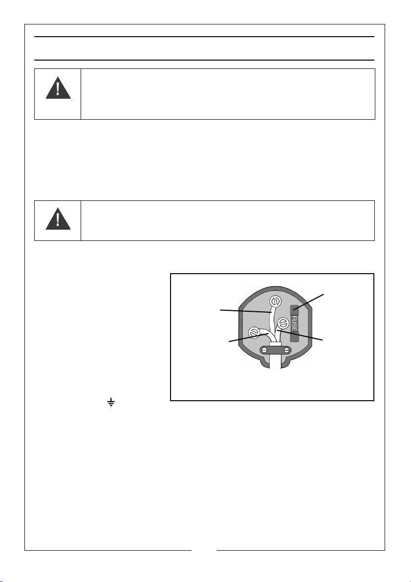
ELECTRICAL CONNECTIONS
Plug must be BS1363/A approved.
Always fit
Ensure that the outer sheath of
Neutral
(Blue)
Live
(Brown)
Earth
(Green and
a 13 Amp
the cable is firmly held by the clamp
fuse.
Yel low)
WARNING: READ THESE ELECTRICAL SAFETY INSTRUCTIONS
THOROUGHLY BEFORE CONNECTING THE PRODUCT TO THE MAINS
SUPPLY.
Connect the mains lead to a standard, 230 Volt (50Hz) electrical supply through
an approved 13 amp BS 1363 plug, or a suitably fused isolator switch.
If the plug has to be changed because it is not suitable for your socket, or
because of damage, it must be removed and a replacement fitted, following
the wiring instructions shown below. The old plug must be discarded safely, as
insertion into a power socket could cause an electrical hazard.
WARNING: THE WIRES IN THE POWER CABLE OF THIS PRODUCT ARE
COLOURED IN ACCORDANCE WITH THE FOLLOWING CODE:
BLUE = NEUTRAL BROWN = LIVE YELLOW AND GREEN = EARTH
If the colours of the wires in the power cable do not agree with the markings on
the plug.
• The BLUE wire must be
connected to the terminal
which is marked N or
coloured black.
• The BROWN wire must be
connected to the terminal
which is marked L or
coloured red.
• The YELLOW AND GREEN
wire must be connected
to the terminal which is
marked E or or
coloured green.
We strongly recommend that this machine is connected to the mains supply
through a Residual Current Device (RCD)
If you are not sure, consult a qualified electrician. DO NOT try to do any repairs.
Parts & Service: 020 8988 7400 / E-mail: [email protected] or [email protected]
6
Page 7
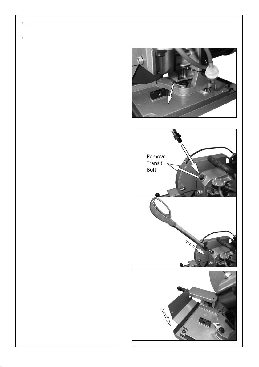
ASSEMBLY
1. Lift the tool from the box using the
handle located on its upper side,
check for damage which may
have occurred in transit.
2. Place the saw on a flat and firm
surface.
3. Free the operating head by
lowering it slightly and turning the
locking plate located at the
machine base.
MOUNTING THE HANDGRIP
1. Remove the transit bolt from the
unit and replace it with the
handle mounting post supplied.
2. Remove the fixing bolt, washers
and nut from the handle.
3. Slide the handle into position.
4. Insert the fixing bolt through the
handle, locking it in place.
5. Replace the washers and nut to
secure the handgrip.
• Make sure that the hand grip is
orientated as shown.
FIT THE SPLASH GUARD
Fit the splash guard supplied to the
front of the tray as shown.
7
Parts & Service: 020 8988 7400 / E-mail: [email protected] or [email protected]
Page 8
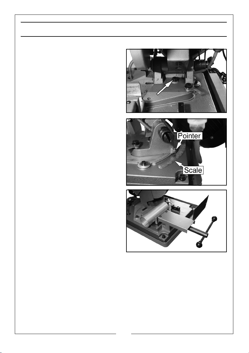
BEFORE USE
SET THE CUTTING ANGLE
1. Loosen the central bolt.
2. Turn the head until the required
angle is reached,
• The pointer and scale are
located at the back of the tool.
3. Tighten the central bolt.
Secure the work in the vice.
Before cutting, secure the work in the
vice and tighten securely.
8
Parts & Service: 020 8988 7400 / E-mail: [email protected] or [email protected]
Page 9
OPERATION
BEFORE STARTING WORK
• All covers and safety devices have to be properly fitted before the
machine is switched on.
• Before you switch on, make sure that the saw blade is correctly fitted
and that the blade guard operates smoothly.
• Before you connect the machine to the power supply, make sure
the data on the rating plate is the same as that for your mains
supply.
• The machine should be operated in a well ventilated area.
WARNING: BEFORE CUTTING, MAKE SURE THAT THE WORKPIECE IS
SECURED IN THE VICE.
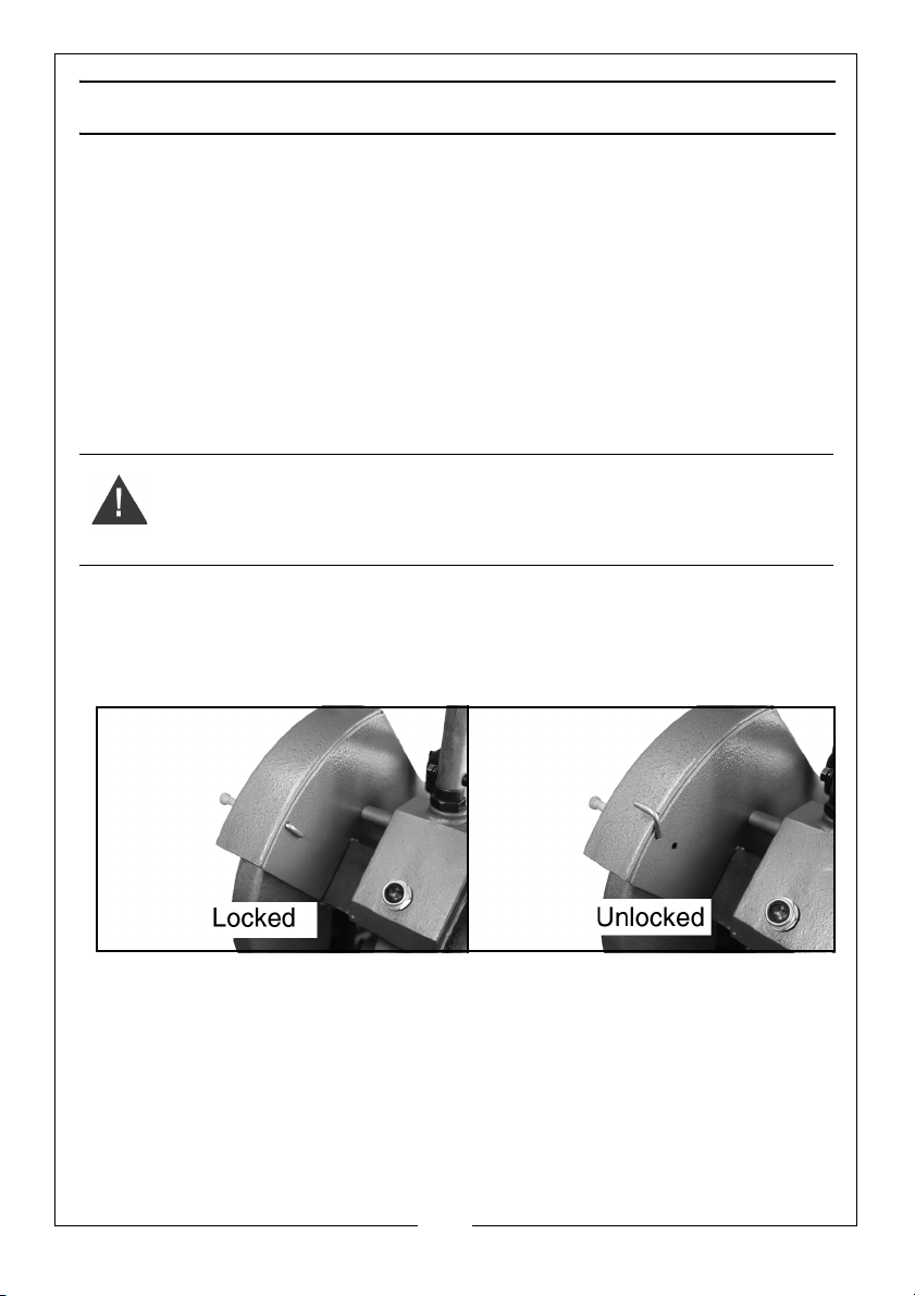
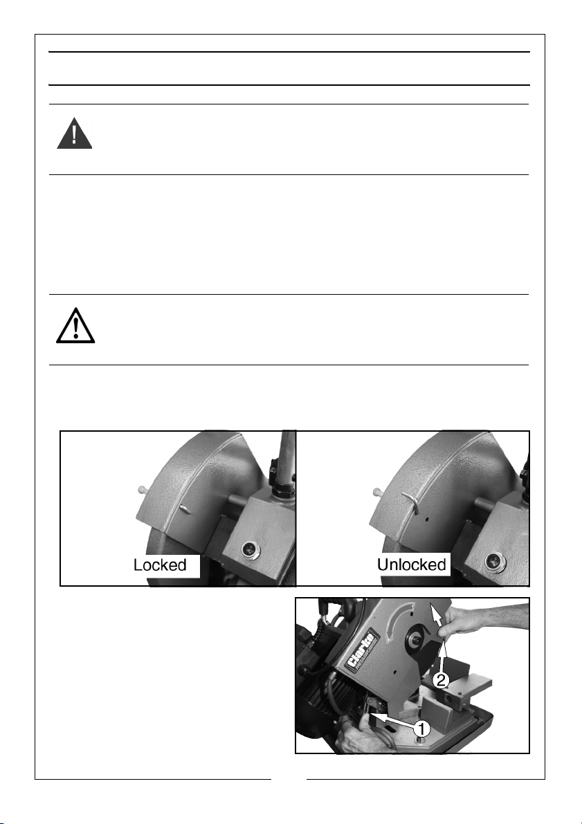
RELEASE THE GUARD LOCK
The tool is equipped with a mechanical safety pin to prevent the blade being
pulled down.
• Pull the pin out and rotate it to the unlocked position before use
• Return the pin to the locked position after use.
9
Parts & Service: 020 8988 7400 / E-mail: [email protected] or [email protected]
Page 10
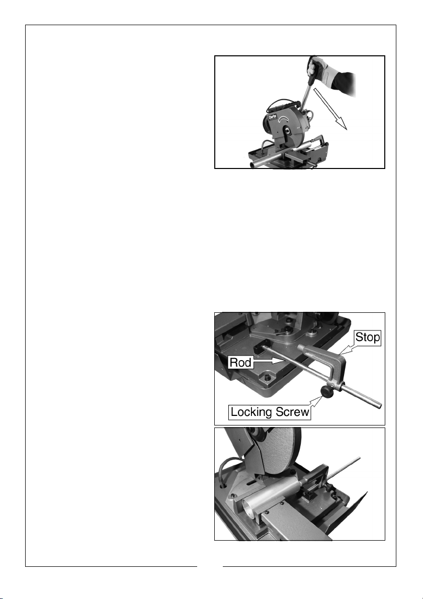
START THE SAW
1. To start the saw, press the trigger
located at the end of the
handgrip.
• Wait for the blade to reach its
maximum speed before
commencing with the cut.
MAKE THE CUT
1. Use the handgrip to pull the saw
into the work.
• Do not force the blade. Allow it to work at its own pace.
• Never remove the blade guards.
SAFETY CLUTCH
The tool is equipped with a safety clutch which protects the machine from
overloading.
If you find that the clutch is activating too often you may need to tighten the
blade.
USING THE STOP
FITTING
1. Screw the rod into the position
shown.
2. Loosen the locking screw on the
stop and slide the stop onto the
rod.
3. Tighten the locking screw to fix the
stop in place.
ADJUSTMENT
1. Loosen the locking screw.
2. Move the stop to the appropriate
position along the rod.
3. Tighten the locking screw.
10
Parts & Service: 020 8988 7400 / E-mail: [email protected] or [email protected]
Page 11
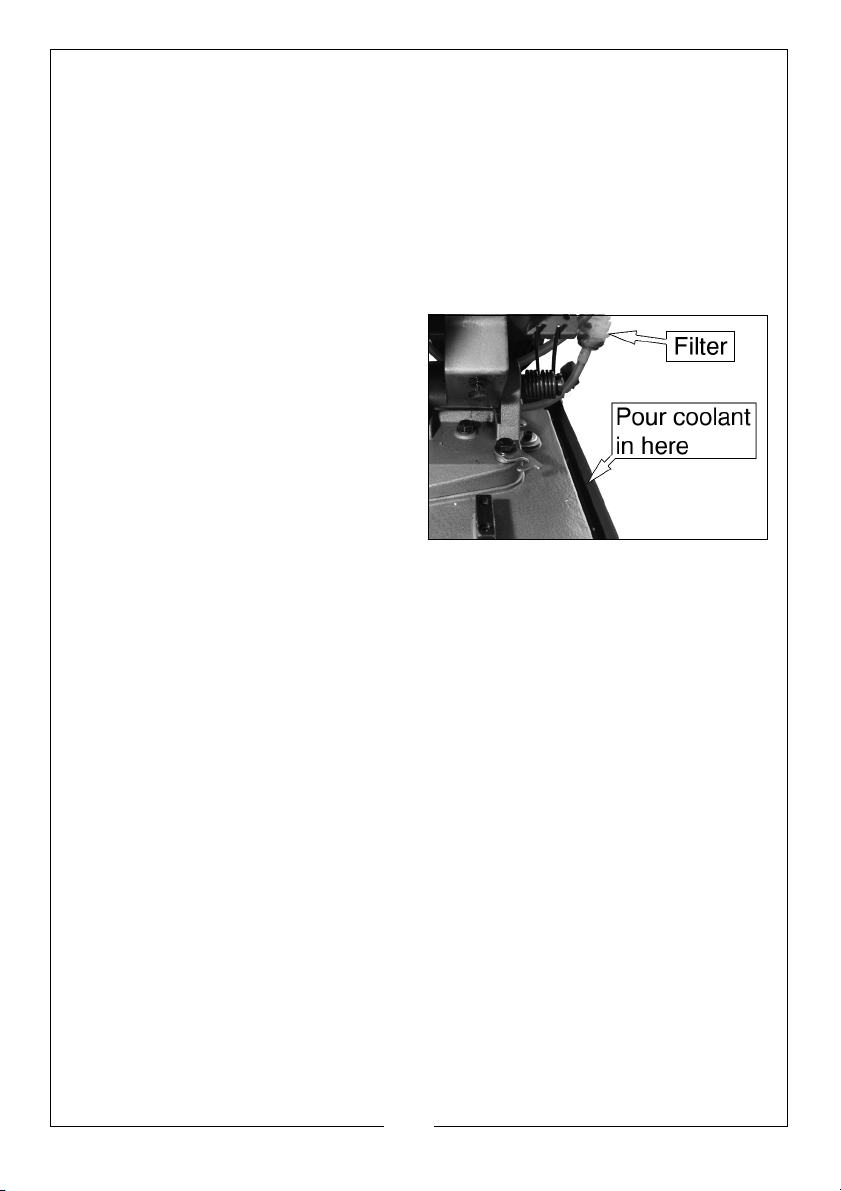
CUTTING FLUID/LUBRICATION
To prevent the material and blade overheating during cutting, lubricate the
blade using coolant poured in the tray.
The coolant is then re-circulated after passing through a purifying filter.
RECOMMENDED FLUID
For general cutting, it is recommended that you use Clarke Professional Metal
Cutting Fluid available from your local Clarke dealer
(Part number 1 litre - 3051059, 5 litre - 3051061)
FILLING
1. Add coolant to the tray (minimum
depth 10 mm).
CLEANING
We recommend that the coolant is removed when the machine is
transported. The tray can then be completely emptied of any debris.
For thorough cleaning, loosen the 4 bolts on the base and remove the entire
machine unit thereby freeing the tray.
COOLANT DISPOSAL
The disposal of coolants is controlled by strict regulations, do not pour coolant
down drains, take it to your local recycling center for safe disposal.
11
Parts & Service: 020 8988 7400 / E-mail: [email protected] or [email protected]
Page 12
MAINTENANCE
WARNING: REMOVE THE PLUG FROM THE MAINS POWER SUPPLY BEFORE
CARRYING OUT ANY ADJUSTMENT. SERVICING OR MAINTENANCE
• Remove dust and dirt regularly from the machine. Cleaning is best
carried out with a fine brush or a cloth.
• Never use caustic agents to clean plastic parts.
• Keep the saw unit clean.
BLADE REPLACEMENT
CAUTION: WHEN MOUNTING THE BLADE, MAKE SURE THAT THE
DIRECTION OF THE ARROW ON THE SURFACE OF THE BLADE MATCHES
THE DIRECTION OF THE ARROW ON THE BLADE GUARD.
With the operating head in the raised position:
1. Release the guard lock
2. Press the end of the lever shown
(1) and rotate the blade guard by
hand towards the rear (2).
• You should now have access to
the blade.
• DO NOT REMOVE THE BLADE
GUARDS.
12
Parts & Service: 020 8988 7400 / E-mail: [email protected] or [email protected]
Page 13
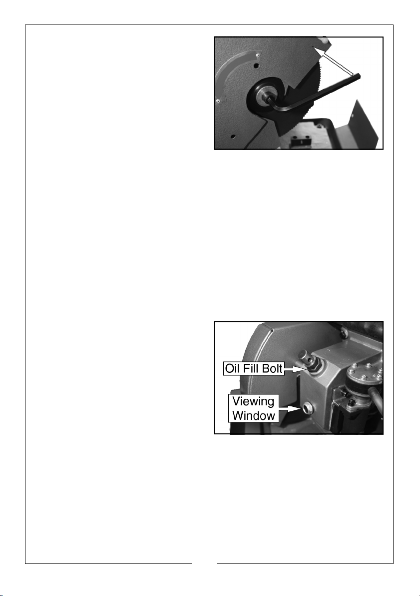
3. Use a Hexagonal key (10mm) to
loosen the blade securing bolt.
4. Remove the outer blade retaining
flange.
5. Remove the used blade and
insert the replacement blade.
• Make sure that the tooth
inclination runs in the same
direction as the arrow on the
blade guard.
• Replacement blades are available from your Clarke Dealer (Part
Number 6469017)
6. Thoroughly clean the outer and inner blade flanges before fitting them (be
careful to insert them accurately on the shaft).
7. Replace and tighten the blade securing bolt.
8. Slide the blade guard back into position.
9. Before plugging the saw in, lower the body and make sure the blade turns
smoothly and that the blade guard works correctly.
MOTOR OIL
Regularly check the motor oil level using the viewing window.
1. Remove the handgrip.
2. Remove the oil fill bolt.
3. Pour the oil into this opening.
• Recommended oil is Shell gear
oil or Mobil gear oil No. 90.
4. Replace the oil fill bolt, and
handgrip.
13
Parts & Service: 020 8988 7400 / E-mail: [email protected] or [email protected]
Page 14
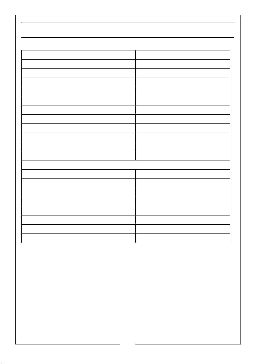
SPECIFICATIONS
Motor Voltage 230V 50Hz 1Phase
Rated Power 720W
Operating Temperature 5 to 40 °C
Blade Speed 86 rpm
Blade Diameter: 225 mm Ø
Blade Bore Diameter 32 mm Ø
Blade Thickness: 1.9 mm
Number of teeth: 150
Product Dimensions (L x W x H) 574 x 346 x 738 mm
Weight (Unpacked) 32.7 kg
Sound Pressure level: dB LpA 85 dB
Sound Power level: dB LWA 94 dB
Cutting Capacities:
Round Hollow Section @ 0º / 45º 65 / 60 mm
Square Hollow Section @ 0º / 45º 60 / 50 mm
Rectangle Hollow Section @ 0º / 45º 70 x 55 / 60 x 40 mm
Round Solid Section @ 0º / 45º 45 / 45 mm
Square Solid Section @ 0º / 45º 40 / 40 mm
Cutting Angle Range: 0 (90 º) - 45º
Vice Size: Width x Opening 82 x 72 mm
Coolant Flow Rate: 206 ml/min
Please note that the details and specifications contained herein, are correct
at the time of going to print. We reserve the right to change specifications at
any time without prior notice.
14
Parts & Service: 020 8988 7400 / E-mail: [email protected] or [email protected]
Page 15
Page 16
Page 17
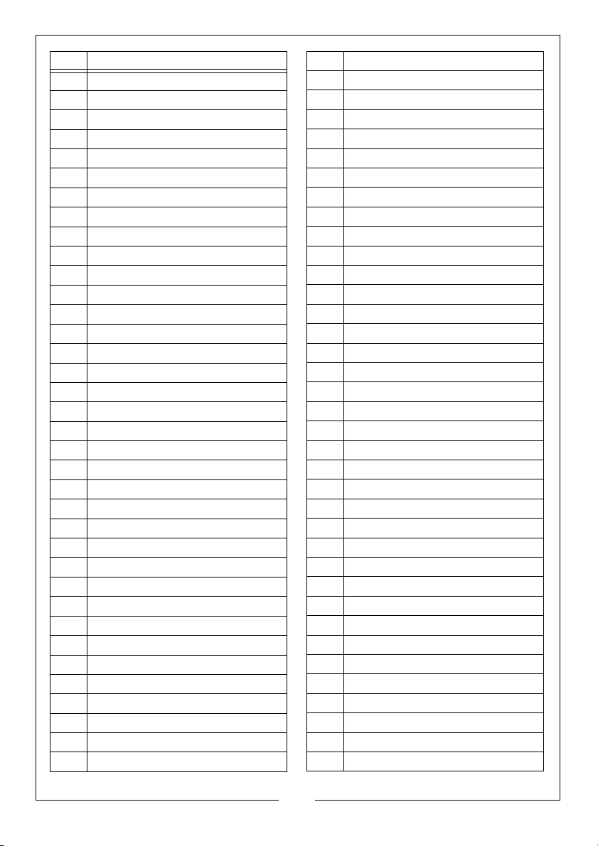
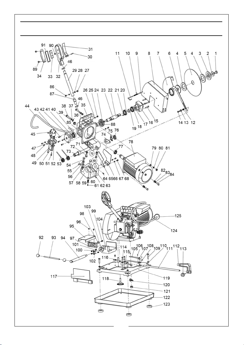
No Part Name
1 Hex. Screw M12 x 20
2 Washer 12mm
3Outer flange
4 Friction plate
5Blade
6 Inner flange
7 Inner blade guide
8 Outer blade guide
9End cap
10 Spring C
11 Locking pin
12 Spring A
13 Thin washer
14 Special screw
15 Hex. screw M6x30
16 Bearing seat B
17 Oil seal 25 x 40 x 7
18 Bearing 61905
19 Spacer bush A
20 Bearing 61905
21 Flat key 5 x 5 x 14
22 Shaft, blade
23 Flat key 5 x 5 x 20
24 Worm wheel
25 Bolt M5 x 10
26 Washer 5 mm
27 Bolt M6 x 25
28 Spring washer 6mm
29 Rod-handgrip
30 Straight pin 4 x 25
31 Trigger
32 Handgrip
33 Switch
34 Cover,handgrip
35 Handle
36 Washer 8 mm
No Part Name
37 Spring washer 8 mm
38 Hex. screw M8 x 45
39 Oil window
40 Bearing 6004
41 Oil seal 20x35x7
42 Bearing seat A
43 Hex.screw M5x16
44 Discharge hose
45 Pump
46 Hex. nut M16
47 Washer 5mm
48 Bolt M5x10
49 Plate, pump
50 Cover, pump
51 Hex. screw M6 x 20
52 Hex. nut M6
53 Torsional spring
54 Hex.screw M10 x 20
55 Corrugation pad 12mm
56 Coupling plate
57 Bush
58 Rotating base
59 Indicator
60 Washer 4 mm
61 Bolt M4 x 8
62 Washer 12 mm
63 Hex. screw M12 x 45
64 Hex.screw M6 x 12
65 Blade safety guard A
66 Blade safety guard B
67 Washer 5 mm
68 Bolt M5 x 10
69 Hex.screw M8 x 25
70 Hex.nut M8
71 Hex. nut M10
72 Hex. Screw M10 x 20
17
Parts & Service: 020 8988 7400 / E-mail: [email protected] or [email protected]
Page 18
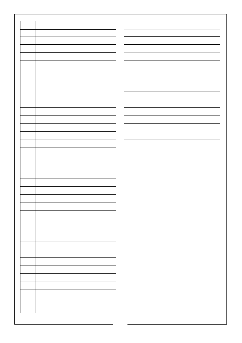
No Part Name
73 Rotate shaft
74 Locking plate
75 Star washer 20 mm
76 Nut M20 x 1.5
77 Bearing 6002
78 Motor
79 Washer 8mm
80 Spring washer 8mm
81 Hex. Nut M8
82 Washer 8mm
83 Spring washer 8mm
84 Hex. screw M8 x 25
85 Gear box
86 Hex. nut M6
87 Seat, handgrip rod
88 Spacer bush B
89 Self tapping screw
90 Rubber plug
91 Rubber washer
92 End cap
93 Lever rod
94 Rod
95 Vice cover,
96 Bolt M5 x 8
97 Adjustable jaw
98 Washer 6mm
99 Hex.screw M6 x 12
100 Hex.screw M5 x 30
101 Spring B
102 Hex screw M6 x 30
103 Special nut
104 Fixed jaw
105 Scale
106 Rivet
107 Hex. screw M6 x 10
108 Eccentric washer
No Part Name
109 Hex.screw M8 x 35
110 Washer 8mm
111 Bar-stop-rod
112 Bar-stop
113 Handle M6 x 12
114 Hex.screw M6 x 20
115 Seat, bar-stop-rod
116 Straight pin 8 x 20
117 Block plate
118 Filter gauze
119 Base
120 Locking plate
121 Hex.nut M12
122 Water tank
123 Rubber foot
124 Inlet hose
125 Filter
Part code EFCPMCS1
18
Parts & Service: 020 8988 7400 / E-mail: [email protected] or [email protected]
Page 19
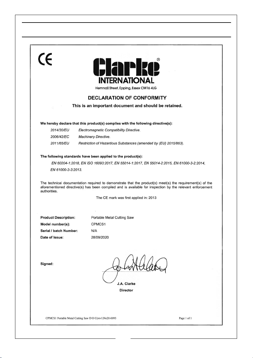
DECLARATION OF CONFORMITY
19
Parts & Service: 020 8988 7400 / E-mail: [email protected] or [email protected]
Page 20

 Loading...